Page 1006 of 4731
VEHICLE SECURITY (THEFT WARNING) SYSTEM BL-191
C
D E
F
G H
J
K L
M A
B
BL
Revision: 2005 July 2005 FX
CAN Communication System DescriptionAIS004OU
CAN (Controller Area Network) is a serial communication line for real time application. It is an on-vehicle mul-
tiplex communication line with high data communication speed and excellent error detection ability. Many elec-
tronic control units are equipped onto a vehicle, and each control unit shares information and links with other
control units during operation (not independent). In CAN communication, control units are connected with 2
communication lines (CAN H line, CAN L line) allowing a high rate of information transmission with less wiring.
Each control unit transmits/receives data but selectively reads required data only.
CAN Communication UnitAIS004OV
Refer to LAN-30, "CAN COMMUNICATION" .
Page 1007 of 4731
BL-192
VEHICLE SECURITY (THEFT WARNING) SYSTEM
Revision: 2005 July 2005 FX
SchematicAIS004OW
TIWM0978E
Page 1008 of 4731
VEHICLE SECURITY (THEFT WARNING) SYSTEM BL-193
C
D E
F
G H
J
K L
M A
B
BL
Revision: 2005 July 2005 FX
Wiring Diagram -VEHSEC-AIS004OX
TIWM0979E
Page 1009 of 4731
BL-194
VEHICLE SECURITY (THEFT WARNING) SYSTEM
Revision: 2005 July 2005 FX
TIWM0550E
Page 1010 of 4731
VEHICLE SECURITY (THEFT WARNING) SYSTEM BL-195
C
D E
F
G H
J
K L
M A
B
BL
Revision: 2005 July 2005 FX
TIWH0094E
Page 1011 of 4731
BL-196
VEHICLE SECURITY (THEFT WARNING) SYSTEM
Revision: 2005 July 2005 FX
TIWM0337E
Page 1012 of 4731
VEHICLE SECURITY (THEFT WARNING) SYSTEM BL-197
C
D E
F
G H
J
K L
M A
B
BL
Revision: 2005 July 2005 FX
TIWM0551E
Page 1013 of 4731

BL-198
VEHICLE SECURITY (THEFT WARNING) SYSTEM
Revision: 2005 July 2005 FX
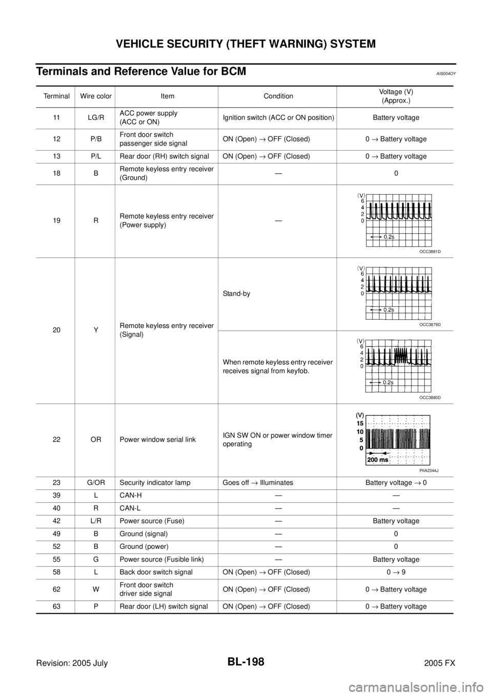
Terminals and Reference Value for BCMAIS004OY
Terminal Wire color Item Condition Voltage (V)
(Approx.)
11 L G / R ACC power supply
(ACC or ON) Ignition switch (ACC or ON position) Battery voltage
12 P/B Front door switch
passenger side signal ON (Open)
→ OFF (Closed) 0 → Battery voltage
13 P/L Rear door (RH) switch signal ON (Open) → OFF (Closed) 0 → Battery voltage
18 B Remote keyless entry receiver
(Ground) —0
19 R Remote keyless entry receiver
(Power supply) —
20 Y Remote keyless entry receiver
(Signal) Stand-by
When remote keyless entry receiver
receives signal from keyfob.
22 OR Power window serial link IGN SW ON or power window timer
operating
23 G/OR Security indicator lamp Goes off → Illuminates Battery voltage → 0
39 L CAN-H — —
40 R CAN-L — —
42 L/R Power source (Fuse) — Battery voltage
49 B Ground (signal) — 0
52 B Ground (power) — 0
55 G Power source (Fusible link) — Battery voltage
58 L Back door switch signal ON (Open) → OFF (Closed) 0 → 9
62 W Front door switch
driver side signal ON (Open)
→ OFF (Closed) 0 → Battery voltage
63 P Rear door (LH) switch signal ON (Open) → OFF (Closed) 0 → Battery voltage
OCC3881D
OCC3879D
OCC3880D
PIIA2344J