Page 1414 of 4731
![INFINITI FX35 2005 Service Manual INDEX FOR DTC EC-21
[VQ35DE]
C
D E
F
G H
I
J
K L
M A
EC
Revision: 2005 July 2005 FXHLR/C SOL FNCTN P1769 1769 AT- 1 6 4
HLR/C SOL/CIRC P1767 1767AT- 1 6 2
HO2S2 (B1) P0138 0138EC-228
HO2S](/manual-img/42/57020/w960_57020-1413.png "INFINITI FX35 2005 Service Manual INDEX FOR DTC EC-21
[VQ35DE]
C
D E
F
G H
I
J
K L
M A
EC
Revision: 2005 July 2005 FXHLR/C SOL FNCTN P1769 1769 AT- 1 6 4
HLR/C SOL/CIRC P1767 1767AT- 1 6 2
HO2S2 (B1) P0138 0138EC-228
HO2S")
INDEX FOR DTC EC-21
[VQ35DE]
C
D E
F
G H
I
J
K L
M A
EC
Revision: 2005 July 2005 FXHLR/C SOL FNCTN P1769 1769 AT- 1 6 4
HLR/C SOL/CIRC P1767 1767AT- 1 6 2
HO2S2 (B1) P0138 0138EC-228
HO2S2 (B1) P0139 0139EC-237
HO2S2 (B1) P1146 1146EC-442
HO2S2 (B1) P1147 1147EC-453
HO2S2 (B2) P0158 0158EC-228
HO2S2 (B2) P0159 0159EC-237
HO2S2 (B2) P1166 1166EC-442
HO2S2 (B2) P1167 1167EC-453
HO2S2 HTR (B1) P0037 0037EC-178
HO2S2 HTR (B1) P0038 0038EC-178
HO2S2 HTR (B2) P0057 0057EC-178
HO2S2 HTR (B2) P0058 0058EC-178
I/C SOLENOID/CIRC P1752 1752 AT- 1 5 0
I/C SOLENOID FNCTN P1754 1754AT- 1 5 2
IAT SEN/CIRCUIT P0112 0112EC-203
IAT SEN/CIRCUIT P0113 0113EC-203
IAT SENSOR P0127 0127EC-223
INT/V TIM CONT-B1 P0011 0011EC-174
INT/V TIM CONT-B2 P0021 0021EC-174
I N T / V T I M V / C I R - B 1 P 1111 1111EC-417
INT/V TIM V/CIR-B2 P1136 1136EC-417
ISC SYSTEM P0506 0506EC-393
ISC SYSTEM P0507 0507EC-395
KNOCK SEN/CIRC-B1 P0327 0327EC-295
KNOCK SEN/CIRC-B1 P0328 0328EC-295
L/PRESS SOL/CIRC P0745 0745 AT- 1 2 9
LC/B SOLENOID FNCT P1774 1774AT- 1 6 8
LC/B SOLENOID/CIRC P1772 1772AT- 1 6 6
MAF SEN/CIRCUIT P0101 0101EC-186
MAF SEN/CIRCUIT P0102 0102EC-195
MAF SEN/CIRCUIT P0103 0103EC-195
MULTI CYL MISFIRE P0300 0300EC-285
NATS MALFUNCTION P1610 - P1615 1610 - 1615 EC-53
NO DTC IS DETECTED.
FURTHER TESTING
MAY BE REQUIRED. P0000 0000 —
P-N POS SW/CIRCUIT P1706 1706 EC-609
PNP SW/CIRC P0705 0705 AT- 11 4
PURG VOLUME CONT/V P0444 0444EC-336
PURG VOLUME CONT/V P0445 0445EC-336
PURG VOLUME CONT/V P1444 1444EC-560
Items
(CONSULT-II screen terms) DTC*
1
Reference page
CONSULT-II
GST*
2ECM*3
Page 1415 of 4731
![INFINITI FX35 2005 Service Manual EC-22
[VQ35DE]
INDEX FOR DTC
Revision: 2005 July 2005 FX
*1: 1st trip DTC No. is the same as DTC No.
*2: This number is prescribed by SAE J2012.
*3: In Diagnostic Test Mode II (Self-diagnostic resul](/manual-img/42/57020/w960_57020-1414.png "INFINITI FX35 2005 Service Manual EC-22
[VQ35DE]
INDEX FOR DTC
Revision: 2005 July 2005 FX
*1: 1st trip DTC No. is the same as DTC No.
*2: This number is prescribed by SAE J2012.
*3: In Diagnostic Test Mode II (Self-diagnostic resul")
EC-22
[VQ35DE]
INDEX FOR DTC
Revision: 2005 July 2005 FX
*1: 1st trip DTC No. is the same as DTC No.
*2: This number is prescribed by SAE J2012.
*3: In Diagnostic Test Mode II (Self-diagnostic results), this number is controlled by NISSAN.
*4: The troubleshooting for this DTC needs CONSULT-II.
*5: When the fail-safe operations for both self-diagnoses occur, the MIL illuminates.
*6: For models with ICC or ASCD system.
*7: For models with ICC system. PW ST P SEN/CIRC P0550 0550
EC-397
SENSOR POWER/CIRC P1229 1229EC-483
TCM P0700 0700 AT- 11 3
TCC SOLENOID/CIRC P0740 0740AT-125
TCS C/U FUNCTN P1211 1211EC-465
TCS/CIRC P1212 1212EC-466
THERMSTAT FNCTN P0128 0128EC-226
TP SEN 1/CIRC P0222 0222EC-278
TP SEN 1/CIRC P0223 0223EC-278
TP SEN 2/CIRC P0122 0122EC-213
TP SEN 2/CIRC P0123 0123EC-213
TP SEN/CIRC A/T P1705 1705 AT-133
TP SENSOR P2135 2135EC-633
TURBINE REV S/CIRC P1716 1716 AT-141
TW CATALYST SYS-B1 P0420 0420EC-316
TW CATALYST SYS-B2 P0430 0430EC-316
VEH SPD SEN/CIR AT*5P0720 0720AT- 11 8
VEH SPEED SEN/CIRC*5P0500 0500EC-391
VENT CONTROL VALVE P0447 0447 EC-343
VENT CONTROL VALVE P1446 1446EC-568
Items
(CONSULT-II screen terms) DTC*
1
Reference page
CONSULT-II
GST*
2ECM*3
Page 1416 of 4731
![INFINITI FX35 2005 Service Manual PRECAUTIONS EC-23
[VQ35DE]
C
D E
F
G H
I
J
K L
M A
EC
Revision: 2005 July 2005 FX
PRECAUTIONSPFP:00001
Precautions for Supplemental Restraint System (SRS) “AIR BAG” and “SEAT
BELT](/manual-img/42/57020/w960_57020-1415.png "INFINITI FX35 2005 Service Manual PRECAUTIONS EC-23
[VQ35DE]
C
D E
F
G H
I
J
K L
M A
EC
Revision: 2005 July 2005 FX
PRECAUTIONSPFP:00001
Precautions for Supplemental Restraint System (SRS) “AIR BAG” and “SEAT
BELT")
PRECAUTIONS EC-23
[VQ35DE]
C
D E
F
G H
I
J
K L
M A
EC
Revision: 2005 July 2005 FX
PRECAUTIONSPFP:00001
Precautions for Supplemental Restraint System (SRS) “AIR BAG” and “SEAT
BELT PRE-TENSIONER”
ABS00A2R
The Supplemental Restraint System such as “AIR BAG” and “SEAT BELT PRE-TENSIONER”, used along
with a front seat belt, helps to reduce the risk or severity of injury to the driver and front passenger for certain
types of collision. This system includes seat belt switch inputs and dual stage front air bag modules. The SRS
system uses the seat belt switches to determine the front air bag deployment, and may only deploy one front
air bag, depending on the severity of a collision and whether the front occupants are belted or unbelted.
Information necessary to service the system safely is included in the SRS and SB section of this Service Man-
ual.
WARNING:
�To avoid rendering the SRS inoperative, which could increase the risk of personal injury or death
in the event of a collision which would result in air bag inflation, all maintenance must be per-
formed by an authorized NISSAN/INFINITI dealer.
�Improper maintenance, including incorrect removal and installation of the SRS, can lead to per-
sonal injury caused by unintentional activation of the system. For removal of Spiral Cable and Air
Bag Module, see the SRS section.
�Do not use electrical test equipment on any circuit related to the SRS unless instructed to in this
Service Manual. SRS wiring harnesses can be identified by yellow and/or orange harnesses or
harness connectors.
On Board Diagnostic (OBD) System of Engine and A/TABS006JZ
The ECM has an on board diagnostic system. It will light up the malfunction indicator lamp (MIL) to warn the
driver of a malfunction causing emission deterioration.
CAUTION:
�Be sure to turn the ignition switch OFF and disconnect the negative battery cable before any
repair or inspection work. The open/short circuit of related switches, sensors, solenoid valves,
etc. will cause the MIL to light up.
�Be sure to connect and lock the connectors securely after work. A loose (unlocked) connector will
cause the MIL to light up due to the open circuit. (Be sure the connector is free from water, grease,
dirt, bent terminals, etc.)
�Certain systems and components, especially those related to OBD, may use a new style slide-
locking type harness connector. For description and how to disconnect, refer to PG-74, "
HAR-
NESS CONNECTOR" .
�Be sure to route and secure the harnesses properly after work. The interference of the harness
with a bracket, etc. may cause the MIL to light up due to the short circuit.
�Be sure to connect rubber tubes properly after work. A misconnected or disconnected rubber tube
may cause the MIL to light up due to the malfunction of the EVAP system or fuel injection system,
etc.
�Be sure to erase the unnecessary malfunction information (repairs completed) from the ECM and
TCM (Transmission control module) before returning the vehicle to the customer.
PrecautionABS006K0
�Always use a 12 volt battery as power source.
�Do not attempt to disconnect battery cables while engine is
running.
�Before connecting or disconnecting the ECM harness con-
nector, turn ignition switch OFF and disconnect negative
battery cable. Failure to do so may damage the ECM
because battery voltage is applied to ECM even if ignition
switch is turned OFF.
�Before removing parts, turn ignition switch OFF and then
disconnect negative battery cable.
SEF289H
Page 1417 of 4731
![INFINITI FX35 2005 Service Manual EC-24
[VQ35DE]
PRECAUTIONS
Revision: 2005 July 2005 FX
�Do not disassemble ECM.
�If a battery cable is disconnected, the memory will return to
the ECM value.
The ECM will now start to self-control at](/manual-img/42/57020/w960_57020-1416.png "INFINITI FX35 2005 Service Manual EC-24
[VQ35DE]
PRECAUTIONS
Revision: 2005 July 2005 FX
�Do not disassemble ECM.
�If a battery cable is disconnected, the memory will return to
the ECM value.
The ECM will now start to self-control at")
EC-24
[VQ35DE]
PRECAUTIONS
Revision: 2005 July 2005 FX
�Do not disassemble ECM.
�If a battery cable is disconnected, the memory will return to
the ECM value.
The ECM will now start to self-control at its initial value.
Engine operation can vary slightly when the terminal is dis-
connected. However, this is not an indication of a malfunc-
tion. Do not replace parts because of a slight variation.
�If the battery is disconnected, the following emission-related diagnostic information will be lost
within 24 hours.
–Diagnostic trouble codes
–1st trip diagnostic trouble codes
–Freeze frame data
–1st trip freeze frame data
–System readiness test (SRT) codes
–Test values
�When connecting ECM harness connector, fasten it
securely with a lever as far as it will go as shown in the fig-
ure.
�When connecting or disconnecting pin connectors into or
from ECM, take care not to damage pin terminals (bend or
break).
Make sure that there are not any bends or breaks on ECM
pin terminal, when connecting pin connectors.
�Securely connect ECM harness connectors.
A poor connection can cause an extremely high (surge)
voltage to develop in coil and condenser, thus resulting in
damage to ICs.
�Keep engine control system harness at least 10 cm (4 in)
away from adjacent harness, to prevent engine control sys-
tem malfunctions due to receiving external noise, degraded
operation of ICs, etc.
�Keep engine control system parts and harness dry.
PBIB1164E
PBIB1512E
PBIB0090E
Page 1418 of 4731
![INFINITI FX35 2005 Service Manual PRECAUTIONS EC-25
[VQ35DE]
C
D E
F
G H
I
J
K L
M A
EC
Revision: 2005 July 2005 FX
�Before replacing ECM, perform “ECM Terminals and Refer-
ence Value” inspection and make sure ECM fu](/manual-img/42/57020/w960_57020-1417.png "INFINITI FX35 2005 Service Manual PRECAUTIONS EC-25
[VQ35DE]
C
D E
F
G H
I
J
K L
M A
EC
Revision: 2005 July 2005 FX
�Before replacing ECM, perform “ECM Terminals and Refer-
ence Value” inspection and make sure ECM fu")
PRECAUTIONS EC-25
[VQ35DE]
C
D E
F
G H
I
J
K L
M A
EC
Revision: 2005 July 2005 FX
�Before replacing ECM, perform “ECM Terminals and Refer-
ence Value” inspection and make sure ECM functions prop-
erly. Refer to EC-123
.
�Handle mass air flow sensor carefully to avoid damage.
�Do not disassemble mass air flow sensor.
�Do not clean mass air flow sensor with any type of deter-
gent.
�Do not disassemble electric throttle control actuator.
�Even a slight leak in the air intake system can cause seri-
ous incidents.
�Do not shock or jar the camshaft position sensor (PHASE),
crankshaft position sensor (POS).
�After performing each TROUBLE DIAGNOSIS, perform DTC
Confirmation Procedure or Overall Function Check.
The DTC should not be displayed in the DTC Confirmation
Procedure if the repair is completed. The Overall Function
Check should be a good result if the repair is completed.
�When measuring ECM signals with a circuit tester, never
allow the two tester probes to contact.
Accidental contact of probes will cause a short circuit and
damage the ECM power transistor.
�Do not use ECM ground terminals when measuring input/
output voltage. Doing so may result in damage to the ECM's
transistor. Use a ground other than ECM terminals, such as
the ground.
MEF040D
SEF217U
SEF348N
Page 1419 of 4731
EC-26
[VQ35DE]
PRECAUTIONS
Revision: 2005 July 2005 FX
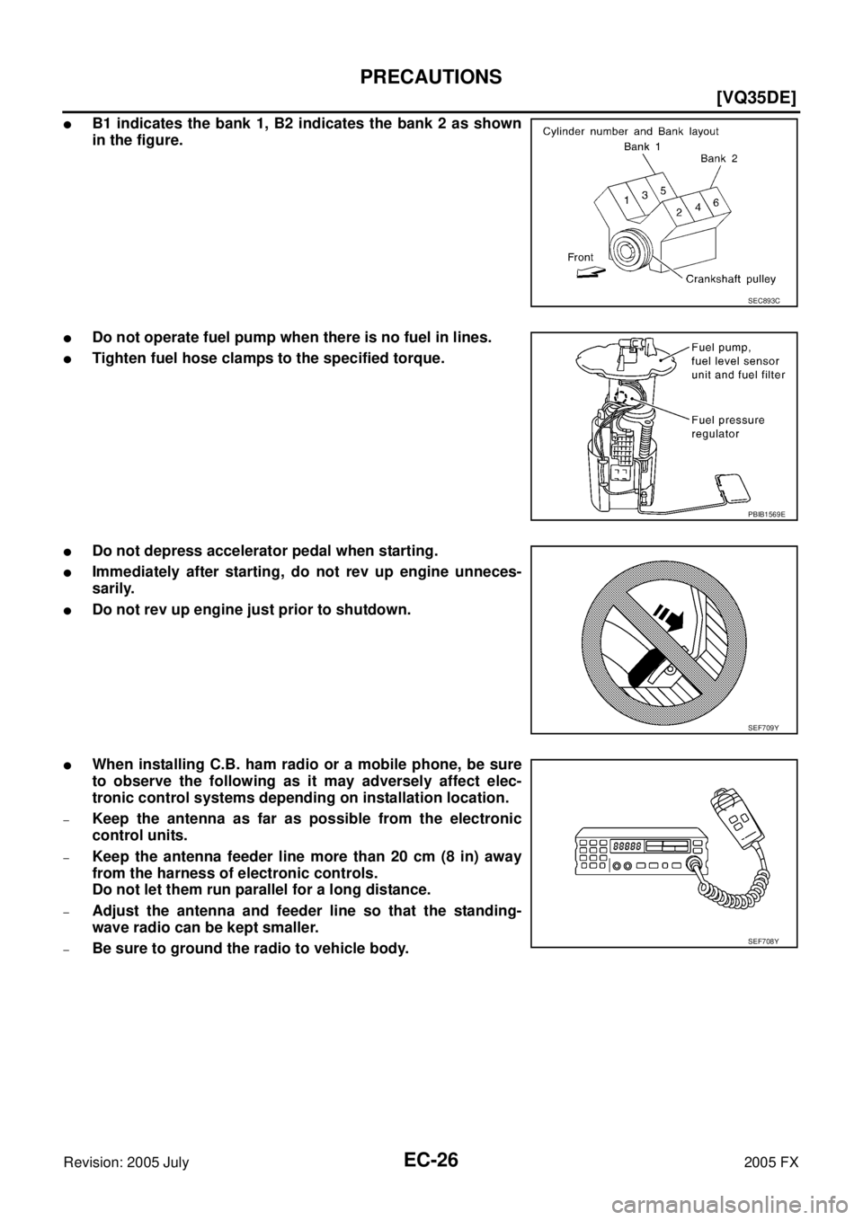
�B1 indicates the bank 1, B2 indicates the bank 2 as shown
in the figure.
�Do not operate fuel pump when there is no fuel in lines.
�Tighten fuel hose clamps to the specified torque.
�Do not depress accelerator pedal when starting.
�Immediately after starting, do not rev up engine unneces-
sarily.
�Do not rev up engine just prior to shutdown.
�When installing C.B. ham radio or a mobile phone, be sure
to observe the following as it may adversely affect elec-
tronic control systems depending on installation location.
–Keep the antenna as far as possible from the electronic
control units.
–Keep the antenna feeder line more than 20 cm (8 in) away
from the harness of electronic controls.
Do not let them run parallel for a long distance.
–Adjust the antenna and feeder line so that the standing-
wave radio can be kept smaller.
–Be sure to ground the radio to vehicle body.
SEC893C
PBIB1569E
SEF709Y
SEF708Y
Page 1420 of 4731
![INFINITI FX35 2005 Service Manual PREPARATION EC-27
[VQ35DE]
C
D E
F
G H
I
J
K L
M A
EC
Revision: 2005 July 2005 FX
PREPARATIONPFP:00002
Special Service ToolsABS006K2
The actual shapes of Kent-Moore tools may differ from](/manual-img/42/57020/w960_57020-1419.png "INFINITI FX35 2005 Service Manual PREPARATION EC-27
[VQ35DE]
C
D E
F
G H
I
J
K L
M A
EC
Revision: 2005 July 2005 FX
PREPARATIONPFP:00002
Special Service ToolsABS006K2
The actual shapes of Kent-Moore tools may differ from")
PREPARATION EC-27
[VQ35DE]
C
D E
F
G H
I
J
K L
M A
EC
Revision: 2005 July 2005 FX
PREPARATIONPFP:00002
Special Service ToolsABS006K2
The actual shapes of Kent-Moore tools may differ from those of special service tools illustrated here.
Tool number
(Kent-Moore No.)
Tool name Description
EG17650301
(J-33984-A)
Radiator cap tester
adapter Adapting radiator cap tester to radiator cap and
radiator filler neck
a: 28 (1.10) dia.
b: 31.4 (1.236) dia.
c: 41.3 (1.626) dia.
Unit: mm (in)
KV10117100
(J-36471-A)
Heated oxygen
sensor wrench Loosening or tightening heated oxygen sensor
with 22 mm (0.87 in) hexagon nut
KV10114400
(J-38365)
Heated oxygen
sensor wrench Loosening or tightening air fuel ratio (A/F) sensor
a: 22 mm (0.87 in)
(J-44321)
Fuel pressure gauge
kit Checking fuel pressure
(J-44321-6)
Fuel pressure adapter Connecting fuel pressure gauge to quick
connector type fuel lines.
(J-44626)
Air fuel ratio (A/F)
sensor wrench Loosening or tightening air fuel ratio (A/F) sensor
1
(J-45488)
Quick connector
release Remove fuel tube quick connectors in engine
room.
S-NT564
S-NT379
S-NT636
LEC642
LBIA0376E
LEM054
PBIC0198E
Page 1421 of 4731
EC-28
[VQ35DE]
PREPARATION
Revision: 2005 July 2005 FX
KV109E0010
(J-46209)
Break-out box Measuring ECM signals with a circuit tester
KV109E0080
(J-45819)
Y-cable adapter Measuring ECM signals with a circuit tester
Tool number
(Kent-Moore No.)
Tool name Description
S-NT825
S-NT826
![INFINITI FX35 2005 Service Manual EC-28
[VQ35DE]
PREPARATION
Revision: 2005 July 2005 FX
KV109E0010
(J-46209)
Break-out box Measuring ECM signals with a circuit tester
KV109E0080
(J-45819)
Y-cable adapter Measuring ECM signals w](/manual-img/42/57020/w960_57020-1420.png "INFINITI FX35 2005 Service Manual EC-28
[VQ35DE]
PREPARATION
Revision: 2005 July 2005 FX
KV109E0010
(J-46209)
Break-out box Measuring ECM signals with a circuit tester
KV109E0080
(J-45819)
Y-cable adapter Measuring ECM signals w")