Page 751 of 4731
AV-152
NAVIGATION SYSTEM
Revision: 2005 July 2005 FX
5. CHECK 3: AUDIO-TX COMMUNICATION SIGNAL
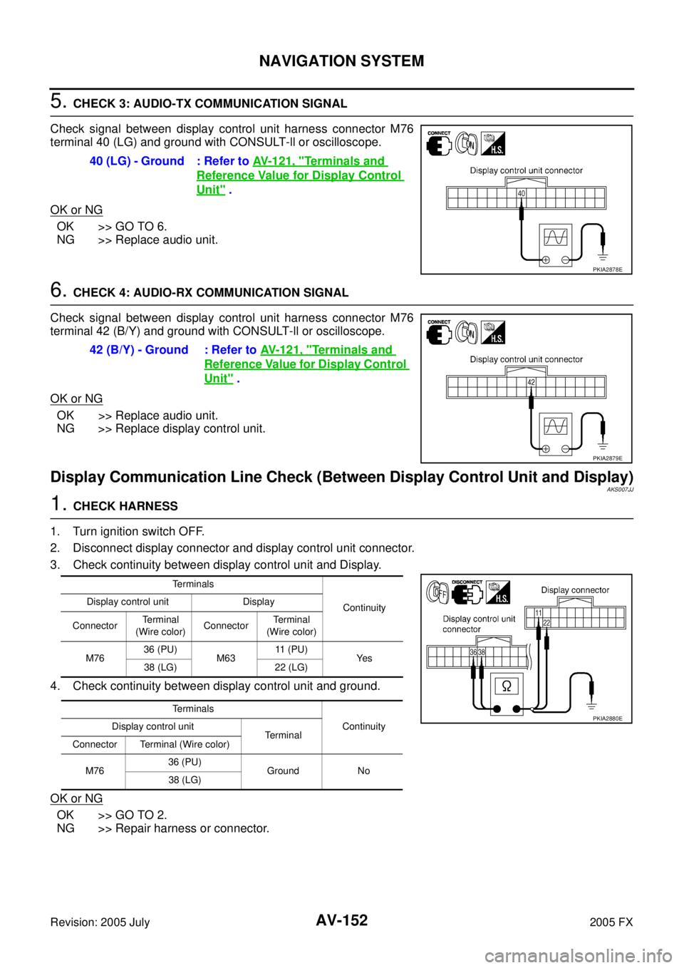
Check signal between display control unit harness connector M76
terminal 40 (LG) and ground with CONSULT-ll or oscilloscope.
OK or NG
OK >> GO TO 6.
NG >> Replace audio unit.
6. CHECK 4: AUDIO-RX COMMUNICATION SIGNAL
Check signal between display control unit harness connector M76
terminal 42 (B/Y) and ground with CONSULT-ll or oscilloscope.
OK or NG
OK >> Replace audio unit.
NG >> Replace display control unit.
Display Communication Line Check (Between Display Control Unit and Display)AKS007JJ
1. CHECK HARNESS
1. Turn ignition switch OFF.
2. Disconnect display connector and display control unit connector.
3. Check continuity between display control unit and Display.
4. Check continuity between display control unit and ground.
OK or NG
OK >> GO TO 2.
NG >> Repair harness or connector. 40 (LG) - Ground : Refer to
AV- 1 2 1 , "
Terminals and
Reference Value for Display Control
Unit" .
PKIA2878E
42 (B/Y) - Ground : Refer to AV- 1 2 1 , "Terminals and
Reference Value for Display Control
Unit" .
PKIA2879E
Terminals
Continuity
Display control unit Display
Connector Terminal
(Wire color) Connector Te r m i n a l
(Wire color)
M76 36 (PU)
M63 11 ( P U )
Ye s
38 (LG) 22 (LG)
Terminals Continuity
Display control unit
Te r m i n a l
Connector Terminal (Wire color)
M76 36 (PU)
Ground No
38 (LG)
PKIA2880E
Page 752 of 4731
NAVIGATION SYSTEM AV-153
C
D E
F
G H
I
J
L
M A
B
AV
Revision: 2005 July 2005 FX
2. CHECK 1: COMMUNICATION SIGNAL (DCU–DSP)
1. Connect display connector.
2. Turn ignition switch ON.
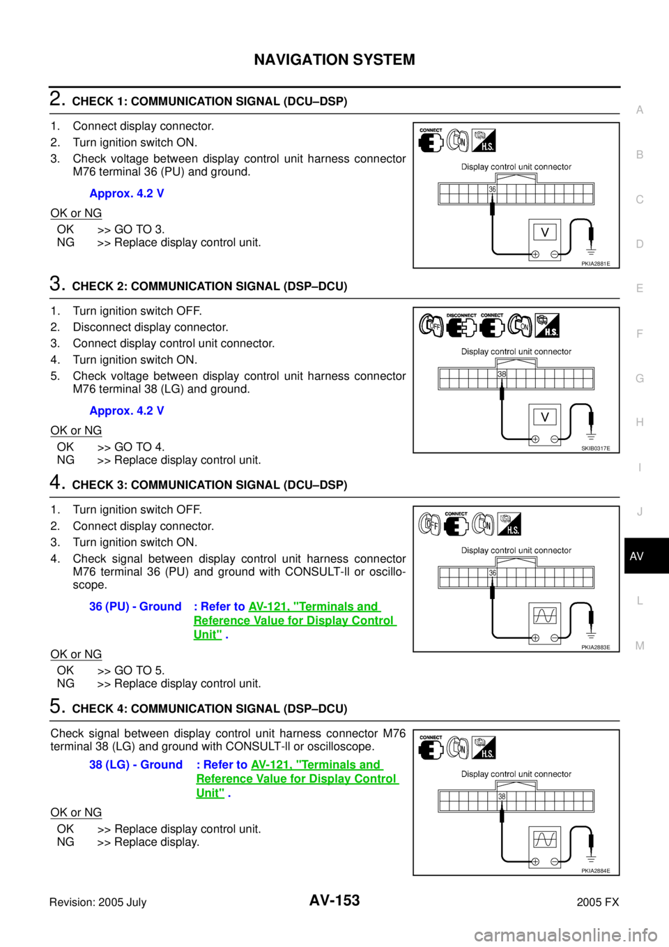
3. Check voltage between display control unit harness connector M76 terminal 36 (PU) and ground.
OK or NG
OK >> GO TO 3.
NG >> Replace display control unit.
3. CHECK 2: COMMUNICATION SIGNAL (DSP–DCU)
1. Turn ignition switch OFF.
2. Disconnect display connector.
3. Connect display control unit connector.
4. Turn ignition switch ON.
5. Check voltage between display control unit harness connector M76 terminal 38 (LG) and ground.
OK or NG
OK >> GO TO 4.
NG >> Replace display control unit.
4. CHECK 3: COMMUNICATION SIGNAL (DCU–DSP)
1. Turn ignition switch OFF.
2. Connect display connector.
3. Turn ignition switch ON.
4. Check signal between display control unit harness connector M76 terminal 36 (PU) and ground with CONSULT-ll or oscillo-
scope.
OK or NG
OK >> GO TO 5.
NG >> Replace display control unit.
5. CHECK 4: COMMUNICATION SIGNAL (DSP–DCU)
Check signal between display control unit harness connector M76
terminal 38 (LG) and ground with CONSULT-ll or oscilloscope.
OK or NG
OK >> Replace display control unit.
NG >> Replace display. Approx. 4.2 V
PKIA2881E
Approx. 4.2 V
SKIB0317E
36 (PU) - Ground : Refer to
AV- 1 2 1 , "Terminals and
Reference Value for Display Control
Unit" .PKIA2883E
38 (LG) - Ground : Refer to AV- 1 2 1 , "Terminals and
Reference Value for Display Control
Unit" .
PKIA2884E
Page 756 of 4731

NAVIGATION SYSTEM AV-157
C
D E
F
G H
I
J
L
M A
B
AV
Revision: 2005 July 2005 FX
2. CHECK HORIZONTAL SYNCHRONIZATION SIGNAL
1. Connect display control unit connector and display connector.
2. Turn ignition switch ON.
3. Check signal between display control unit connector M76 termi- nals 55 (R) and 49 with CONSULT-ll or oscilloscope.
OK or NG
OK >> GO TO 3.
NG >> Replace display.
3. CHECK RGB AREA SIGNAL
1. Press the “TRIP” button.
2. Check signal between display control unit connector M76 termi- nals 51 (B) and 49 with CONSULT-ll or oscilloscope.
OK or NG
OK >> Replace display.
NG >> Replace display control unit.
Color of RGB Image Is Not Proper (NAVI Screen Looks Bluish)AKS007JQ
1. CHECK RGB HARNESS
1. Turn ignition switch OFF.
2. Disconnect NAVI control unit connector and display control unit connector.
3. Check continuity between NAVI control unit and display control unit.
4. Check continuity between NAVI control unit and ground.
�When the screen looks bluish
OK or NG
OK >> GO TO 2.
NG >> Repair harness or connector. 55 (R) - 49 : Refer to
AV- 1 2 1 , "
Terminals and Refer-
ence Value for Display Control Unit" .
PKIA2888E
51 (B) - 49 : Refer to AV- 1 2 1 , "Terminals and Refer-
ence Value for Display Control Unit" .
PKIA2889E
Terminals
Continuity
NAVI control unit Display control unit
Connector Terminal
(Wire color) Connector Terminal
(Wire color)
B208 18 (R)
M76 44 (R/W)
Ye s
17 45
Terminals Continuity
NAVI control unit
—
Connector Terminal (Wire color)
B208 18 (R)
Ground No
17
PKIA2890E
Page 757 of 4731
AV-158
NAVIGATION SYSTEM
Revision: 2005 July 2005 FX
2. CHECK RGB SIGNAL
1. Connect NAVI control unit connector and display control unit connector.
2. Turn ignition switch ON.
3. Display “Color bar” by “CONFIRMATION/ADJUSTMENT” mode.
4. Check the following with CONSULT-ll or oscilloscope.
�When the screen looks bluish
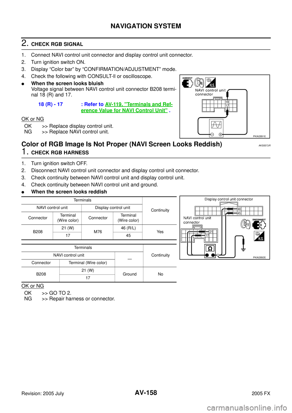
Voltage signal between NAVI control unit connector B208 termi-
nal 18 (R) and 17.
OK or NG
OK >> Replace display control unit.
NG >> Replace NAVI control unit.
Color of RGB Image Is Not Proper (NAVI Screen Looks Reddish)AKS007JR
1. CHECK RGB HARNESS
1. Turn ignition switch OFF.
2. Disconnect NAVI control unit connector and display control unit connector.
3. Check continuity between NAVI control unit and display control unit.
4. Check continuity between NAVI control unit and ground.
�When the screen looks reddish
OK or NG
OK >> GO TO 2.
NG >> Repair harness or connector. 18 (R) - 17 : Refer to
AV- 11 9 , "
Terminals and Ref-
erence Value for NAVI Control Unit" .
PKIA2891E
Terminals
Continuity
NAVI control unit Display control unit
Connector Te r m i n a l
(Wire color) Connector Terminal
(Wire color)
B208 21 (W)
M76 46 (R/L)
Ye s
17 45
Terminals Continuity
NAVI control unit
—
Connector Terminal (Wire color)
B208 21 (W)
Ground No
17
PKIA2892E
Page 758 of 4731
NAVIGATION SYSTEM AV-159
C
D E
F
G H
I
J
L
M A
B
AV
Revision: 2005 July 2005 FX
2. CHECK RGB SIGNAL
1. Connect NAVI control unit connector and display control unit connector.
2. Turn ignition switch ON.
3. Display ″Color bar ″ by ″CONFIRMATION/ADJUSTMENT ″ mode.
4. Check the following with CONSULT-ll or oscilloscope.
�When the screen looks reddish
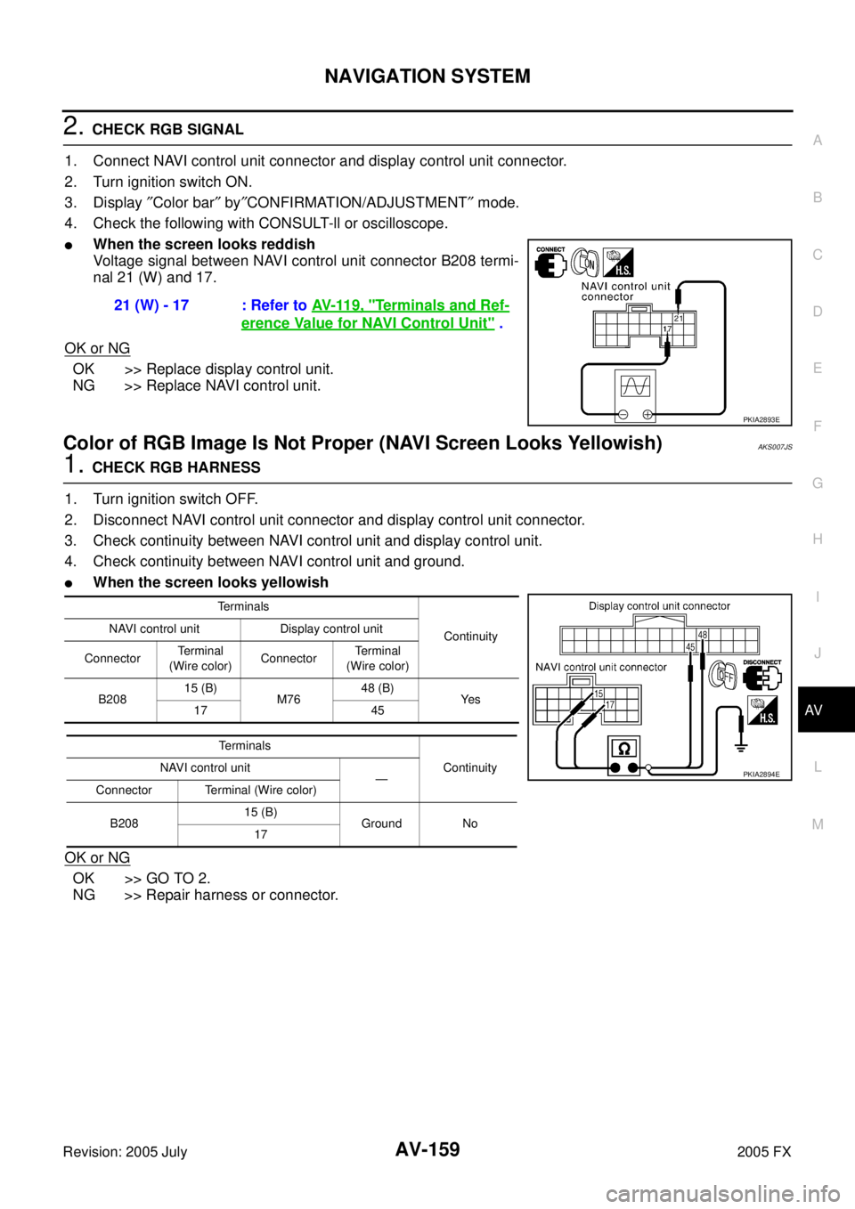
Voltage signal between NAVI control unit connector B208 termi-
nal 21 (W) and 17.
OK or NG
OK >> Replace display control unit.
NG >> Replace NAVI control unit.
Color of RGB Image Is Not Proper (NAVI Screen Looks Yellowish)AKS007JS
1. CHECK RGB HARNESS
1. Turn ignition switch OFF.
2. Disconnect NAVI control unit connector and display control unit connector.
3. Check continuity between NAVI control unit and display control unit.
4. Check continuity between NAVI control unit and ground.
�When the screen looks yellowish
OK or NG
OK >> GO TO 2.
NG >> Repair harness or connector. 21 (W) - 17 : Refer to
AV- 11 9 , "
Terminals and Ref-
erence Value for NAVI Control Unit" .
PKIA2893E
Terminals
Continuity
NAVI control unit Display control unit
Connector Terminal
(Wire color) Connector Terminal
(Wire color)
B208 15 (B)
M76 48 (B)
Ye s
17 45
Terminals Continuity
NAVI control unit
—
Connector Terminal (Wire color)
B208 15 (B)
Ground No
17
PKIA2894E
Page 759 of 4731
AV-160
NAVIGATION SYSTEM
Revision: 2005 July 2005 FX
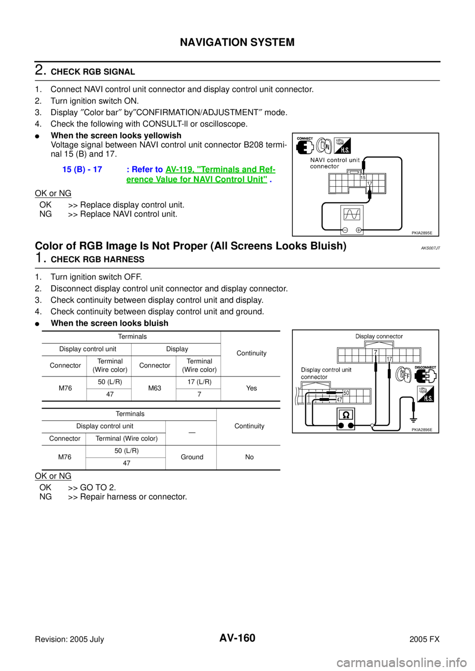
2. CHECK RGB SIGNAL
1. Connect NAVI control unit connector and display control unit connector.
2. Turn ignition switch ON.
3. Display ″Color bar ″ by ″CONFIRMATION/ADJUSTMENT ″ mode.
4. Check the following with CONSULT-ll or oscilloscope.
�When the screen looks yellowish
Voltage signal between NAVI control unit connector B208 termi-
nal 15 (B) and 17.
OK or NG
OK >> Replace display control unit.
NG >> Replace NAVI control unit.
Color of RGB Image Is Not Proper (All Screens Looks Bluish)AKS007JT
1. CHECK RGB HARNESS
1. Turn ignition switch OFF.
2. Disconnect display control unit connector and display connector.
3. Check continuity between display control unit and display.
4. Check continuity between display control unit and ground.
�When the screen looks bluish
OK or NG
OK >> GO TO 2.
NG >> Repair harness or connector. 15 (B) - 17 : Refer to
AV- 11 9 , "
Terminals and Ref-
erence Value for NAVI Control Unit" .
PKIA2895E
Terminals
Continuity
Display control unit Display
Connector Te r m i n a l
(Wire color) Connector Terminal
(Wire color)
M76 50 (L/R)
M63 17 (L/R)
Ye s
47 7
Terminals Continuity
Display control unit
—
Connector Terminal (Wire color)
M76 50 (L/R)
Ground No
47
PKIA2896E
Page 760 of 4731
NAVIGATION SYSTEM AV-161
C
D E
F
G H
I
J
L
M A
B
AV
Revision: 2005 July 2005 FX
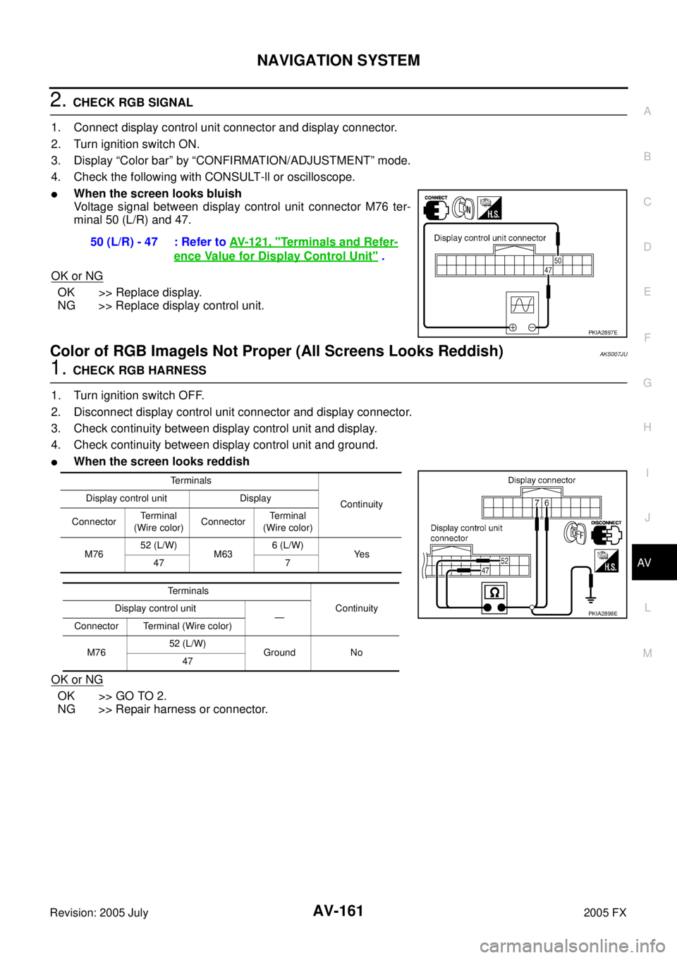
2. CHECK RGB SIGNAL
1. Connect display control unit connector and display connector.
2. Turn ignition switch ON.
3. Display “Color bar” by “CONFIRMATION/ADJUSTMENT” mode.
4. Check the following with CONSULT-ll or oscilloscope.
�When the screen looks bluish
Voltage signal between display control unit connector M76 ter-
minal 50 (L/R) and 47.
OK or NG
OK >> Replace display.
NG >> Replace display control unit.
Color of RGB ImageIs Not Proper (All Screens Looks Reddish)AKS007JU
1. CHECK RGB HARNESS
1. Turn ignition switch OFF.
2. Disconnect display control unit connector and display connector.
3. Check continuity between display control unit and display.
4. Check continuity between display control unit and ground.
�When the screen looks reddish
OK or NG
OK >> GO TO 2.
NG >> Repair harness or connector. 50 (L/R) - 47 : Refer to
AV- 1 2 1 , "
Terminals and Refer-
ence Value for Display Control Unit" .
PKIA2897E
Terminals
Continuity
Display control unit Display
Connector Terminal
(Wire color) Connector Te r m i n a l
(Wire color)
M76 52 (L/W)
M63 6 (L/W)
Ye s
47 7
Te r m i n a l s Continuity
Display control unit
—
Connector Terminal (Wire color)
M76 52 (L/W)
Ground No
47
PKIA2898E
Page 761 of 4731
AV-162
NAVIGATION SYSTEM
Revision: 2005 July 2005 FX
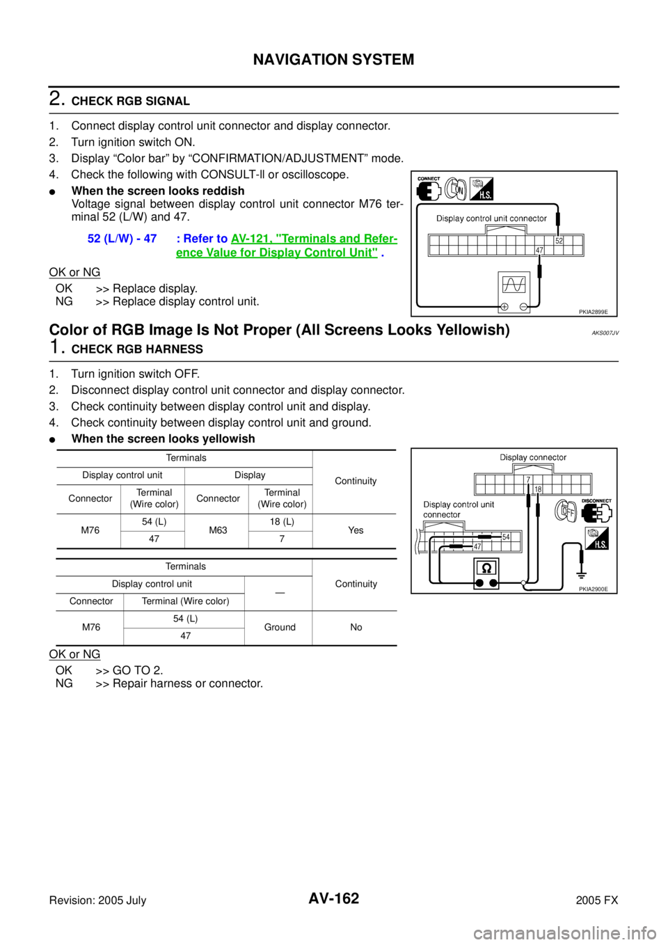
2. CHECK RGB SIGNAL
1. Connect display control unit connector and display connector.
2. Turn ignition switch ON.
3. Display “Color bar” by “CONFIRMATION/ADJUSTMENT” mode.
4. Check the following with CONSULT-ll or oscilloscope.
�When the screen looks reddish
Voltage signal between display control unit connector M76 ter-
minal 52 (L/W) and 47.
OK or NG
OK >> Replace display.
NG >> Replace display control unit.
Color of RGB Image Is Not Proper (All Screens Looks Yellowish)AKS007JV
1. CHECK RGB HARNESS
1. Turn ignition switch OFF.
2. Disconnect display control unit connector and display connector.
3. Check continuity between display control unit and display.
4. Check continuity between display control unit and ground.
�When the screen looks yellowish
OK or NG
OK >> GO TO 2.
NG >> Repair harness or connector. 52 (L/W) - 47 : Refer to
AV- 1 2 1 , "
Terminals and Refer-
ence Value for Display Control Unit" .
PKIA2899E
Terminals
Continuity
Display control unit Display
Connector Terminal
(Wire color) Connector Terminal
(Wire color)
M76 54 (L)
M63 18 (L)
Ye s
47 7
Terminals Continuity
Display control unit
—
Connector Terminal (Wire color)
M76 54 (L)
Ground No
47
PKIA2900E