2005 HYUNDAI XG350 warning lights
[x] Cancel search: warning lightsPage 133 of 247

DRIVING YOUR HYUNDAI
32
KEY POSITIONS COMBINATION IGNITION SWITCH
BEFORE STARTING THE ENGINE
!
C020A01A-AATBefore you start the engine, you should always:
1. Look around the vehicle to be sure there are
no flat tires, puddles of oil, water or other
indications of possible trouble.
2. After entering the car, check to be sure the
parking brake is engaged.
3. Check that all windows, and lights are clean.
4. Check that the interior and exterior mirrors
are clean and in position.
5. Check your seat, seatback and headrest to
be sure they are in their proper positions.
6. Lock all the doors.
7. Fasten your seat belt and be sure that all
other occupants have fastened theirs.
8. Turn off all lights and accessories that are
not needed.
9. When you turn the ignition switch to "ON",
check that all appropriate warning lights are
operating and that you have sufficient fuel.
10.Check the operation of warning lights and all
bulbs when key is in the "ON" position.
C030A01L-AATTo Start the Engineo Place the shift lever in "P" (park) and de-
press the brake pedal fully.
o To start the engine, insert the ignition key and
turn it to the "START" position. Release it as
soon as the engine starts. Do not hold the
key in the "START" position for more than 15
seconds.NOTE:o For safety, the engine will not start if the
shift lever is not in "P" or "N" Position.
o The ignition key cannot be turned from
"ACC" position to "LOCK" position un-
less the shift lever is in the "P" (Park)
position or the negative battery terminal
is disconnected from the battery. To
remove the key, always confirm that the
shift lever is securely positioned in "P"
(Park).
o For additional information about start-
ing, see page 2-4.
C040A01A-AAT
WARNING:
The engine should not be turned off or the
key removed from the ignition key cylinder
while the vehicle is in motion. The steering
wheel is locked by removing the key.o "START"The engine is started in this position. It will crank
until you release the key.NOTE:Do not hold the key in the "START" position
for more than 15 seconds.LOCKACC
ON
START
C040A01E-1
xgflhma-2.p656/16/04, 3:00 PM 3
Page 135 of 247

DRIVING YOUR HYUNDAI
52
AUTOMATIC TRANSAXLE
C050B01L-AATNormal Conditions:The Starting Procedure:
1. Insert key, and fasten the seat belt.
2. Depress the brake pedal fully and place the
selector lever in "P" (park) position.
3. After turning the ignition key to the "ON"
position, make certain all warning lights and
gauges are functioning properly before start-
ing the engine.
4. Turn the ignition key to the "Start" position
and release it when the engine starts.
After the engine has started, allow the engine
to run for 10 to 20 seconds prior to placing
the vehicle in gear.
The starter should not be operated for more
than 15 seconds at a time. Wait 15-30 sec-
onds between starting attempts to protect
the starter from overheating.
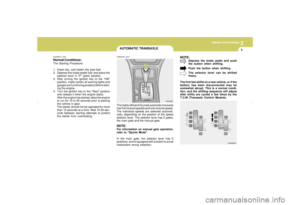
C090A02L-AATThe highly efficient Hyundai automatic transaxle
has five forward speeds and one reverse speed.
The individual speeds are selected automati-
cally, depending on the position of the speed
selector lever. The selector lever has 2 gates;
the main gate and the manual gate.NOTE:For information on manual gate operation,
refer to "Sports Mode".
In the main gate, the selector lever has 5
positions, and is equipped with a button to avoid
inadvertent wrong selection.
NOTE:
Depress the brake pedal and push
the button when shifting.
Push the button when shifting.
The selector lever can be shifted
freely.
The first few shifts on a new vehicle, or if the
battery has been disconnected may be
somewhat abrupt. This is a normal condi-
tion, and the shifting sequence will adjust
after shifts are cycled a few times by the
T.C.M (Transaxle Control Module).
HXG065
C090A02L
xgflhma-2.p656/16/04, 3:00 PM 5
Page 155 of 247

3
WHAT TO DO IN AN EMERGENCY
3
JUMP STARTINGD020A03A-AAT
WARNING:
The gas produced by the battery during the
jump-start operation is highly explosive. If
these instructions are not followed exactly,
serious personal injury and damage to the
vehicle may occur! If you are not sure how
to follow this procedure, seek qualified
assistance. Automobile batteries contain
sulfuric acid. This is poisonous and highly
corrosive. When jump starting, wear pro-
tective glasses and be careful not to get
acid on yourself, your clothing or on the car.
!
D020A01L-1
Booster batteryDischarged
battery
o If you should accidentally get acid on your
skin or in your eyes, immediately remove
any contaminated clothing and flush the area
with clear water for at least 15 minutes. Then
promptly obtain medical attention. If you
must be transported to an emergency facil-
ity, continue to apply water to the affected
area with a sponge or cloth.
o The gas produced by the battery during the
jump-start operation is highly explosive. Do
not smoke or allow a spark or an open flame
in the vicinity.
o The battery being used to provide the jump
start must be 12-volt. If you cannot deter-
mine that it is a 12-volt battery, do not attempt
to use it for the jump start.
o To jump start a car with a discharged battery,
follow this procedure exactly:
1. If the booster battery is installed in another
vehicle, be sure the two vehicles are not
touching.
2. Turn off all unnecessary lights and acces-
sories in both vehicles.
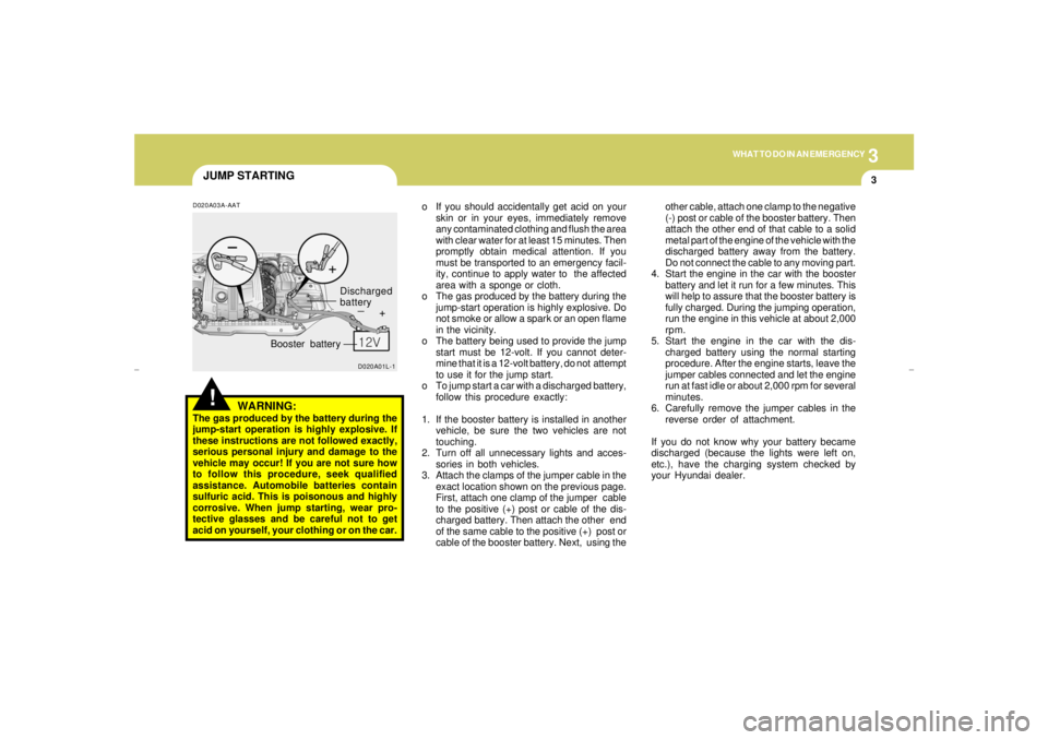
3. Attach the clamps of the jumper cable in the
exact location shown on the previous page.
First, attach one clamp of the jumper cable
to the positive (+) post or cable of the dis-
charged battery. Then attach the other end
of the same cable to the positive (+) post or
cable of the booster battery. Next, using theother cable, attach one clamp to the negative
(-) post or cable of the booster battery. Then
attach the other end of that cable to a solid
metal part of the engine of the vehicle with the
discharged battery away from the battery.
Do not connect the cable to any moving part.
4. Start the engine in the car with the booster
battery and let it run for a few minutes. This
will help to assure that the booster battery is
fully charged. During the jumping operation,
run the engine in this vehicle at about 2,000
rpm.
5. Start the engine in the car with the dis-
charged battery using the normal starting
procedure. After the engine starts, leave the
jumper cables connected and let the engine
run at fast idle or about 2,000 rpm for several
minutes.
6. Carefully remove the jumper cables in the
reverse order of attachment.
If you do not know why your battery became
discharged (because the lights were left on,
etc.), have the charging system checked by
your Hyundai dealer.
xgflhma-3.p656/16/04, 3:00 PM 3
Page 201 of 247

6
DO-IT-YOURSELF MAINTENANCE
21
HEADLIGHT AIMING ADJUSTMENT
!
!
G290A03L-AATHID Type (If Installed)Before performing aiming adjustment, make
sure of the following.
G290A02L-A
Vertical
aiming1. Keep all tires inflated to the correct pressure.
2. Place the vehicle on level ground and press
the front bumper & rear bumper down sev-
eral times. Place vehicle at a distance of 118
in. (3m) from the test wall.
3. See that the vehicle is unloaded (except for
full levels of coolant, engine oil and fuel, and
spare tire, jack, and tools). Have the driver
or equivalent weight placed in driver's seat.
4. Clean the head light lenses and turn on the
headlights (Low beam).
5. Open the hood.
6. Draw the vertical line (through the center of
each headlight) and the horizontal line
(through the center of each headlight) on the
aiming screen.
And then, draw a parallel line at 0.8in.(21mm.)
under the horizontal line.
7. Adjust each cut-off line of the low beam to the
parallel line with a phillips screwdriver -
VERTICAL AIMING
WARNING:
If you need headlight aiming adjustment,
have your vehicle inspected by your Hyundai
Dealer.
Don't attempt to replace or inspect the HID
headlight bulb to prevent danger of an
electric shock.General Type
WARNING:
Horizontal aiming should be adjusted by an
authorized Hyundai Dealer.
G290B02L-AATAdjustment After Headlight Assembly
ReplacementIf the vehicle has had front body repair and the
headlight assembly has been replaced, the
headlight aiming should be checked using an
aiming screen as shown in the illustration. Turn
on the headlight switch. (Low Beam Position)
1. Adjust headlights so that main axis of light is
parallel to center line of the body and is
aligned with point "P" shown in the illustration.
2. Dotted lines in the illustration show center of
headlights.
G290B01L-A
LW
H
HCut-off line
Ground
line
"P" Horizontal lineVertical line
0.83 in. (21 mm)
xgflhma-6.p656/16/04, 2:59 PM 21
Page 216 of 247

6
DO-IT-YOURSELF MAINTENANCE
36
FUSERATING
10A
10A
15A
10A
20A
10A
10A
10A
10A
10A
10A
10A
10APROTECTED COMPONENTS
Door warning & Ignition key illumination, Courtesy lights
Instrument cluster
SRS controls
Automatic transaxle controls, Back-up light switch,
Vehicle speed sensor
Fuel filler door & Trunk lid opener, Driver (Assister) door module
Multipurpose check connector, Audio, lmmobiilizer controls,
Trip computers, Digital clock, Blower & A/C controls, Instrument cluster
Left (Right) inside lights, (HID) Head lights, Fog light relay,
Right HID turn signal light, Right rear combination light
Stop light failure relay
Immobilizer controls, TCS switch, Trip computers, Instrument cluster
ETACM, Hazard switch, Auto light sensor
Antenna, Blower & A/C controls,
Left (Right) outside mirror motor & Folding motor
(HID) Head lights, Front (Rear) cigarette lighters,
Left (Right) license lights, Left HID Turn signal light,
Left rear combination light
Burglar alarm relay, Transaxle range switch, Start relay, ETS controls DESCRIPTION
ROOM LP
A/BAG IND
A/BAG
B/UP
T/LID
D/CLOCK
RH TAIL
SPARE
CLUSTER
T/SIG
RR HTD IND
LH TAIL
START
xgflhma-6.p656/16/04, 2:59 PM 36
Page 244 of 247

10
INDEX
4
J
Jump Starting..................................................................................... 3-3
K
Key .................................................................................................... 1-3
If you lose your keys...................................................................3-13
Positions............................................................................... 2-3 ~ 2-4
L
Lubrication Chart ................................................................................. 9-4
M
Maintenance Intervals
Explanation of scheduled maintenance items...................... 5-7 ~ 5-9
Maintenance under severe usage conditions ................................ 5-6
Scheduled maintenance........................................................ 5-4 ~ 5-5
Service requirements ..................................................................... 5-2
Mirrors
Day-night inside rear view ...........................................................1-61
Outside rearview mirror heater ....................................................1-61
O
Odometer..........................................................................................1-45
Outside rearview mirror ....................................................................1-60 H
Hazard Warning System...................................................................1-50
Headlight Aiming Adjustment ............................................................6-21
Heating and Ventilation ..........................................................1-78 ~ 1-85
Air flow control............................................. 1-80 ~ 1-82, 1-90 ~ 1-91
Air intake control ............................................................... 1-79 ~ 1-80
Bi-level heating ............................................................................1-83
Fan speed control ............................................................... 1-79, 1-88
Temperature control .....................................................................1-82
High-Mounted Rear Stop light ...........................................................1-68
Homelink Mirror................................................................................ 1-62
Hood Release...................................................................................1-72
Horn..................................................................................................1-74
I
Ignition Switch..................................................................................... 2-3
Illuminated Ignition Switch................................................................... 1-4
Instrument Cluster and Indicator Lights............................................1-38
Instrument Panel Light Control (Rheostat).......................................1-52
Intergrated Memory System (I. M. S) ...............................................1-14
Interior Light
Interior light ..................................................................................1-58
Map light ......................................................................................1-58
Personal light...............................................................................1-59
Intermittent Wiper..............................................................................1-49xgflhma-10.p656/16/04, 3:01 PM 4
Page 246 of 247

10
INDEX
6
Automatic..............................................................................2-5 ~ 2-7
Automatic transaxle fluid checking............................................. 6-11
Trip Computer ........................................................................ 1-51 ~ 1-52
Trip Odometer ...................................................................................1-45
Trunk Lid................................................................................ 1-68 ~ 1-68
V
Vehicle Identification Number............................................................. 8-2
Vehicle Load Limit .............................................................................2-19
W
Warning Lights .......................................................................1-40 ~ 1-43
Power Windows.................................................................................. 1-9
Windshield Wiper and Washer Switch..............................................1-48
Windshield Wiper Blades ..................................................................6-10xgflhma-10.p656/16/04, 3:01 PM 6