Page 308 of 539
1
CONTROLS AND EQUIPMENT
3
ZB010D1-E Operation in Foreign Countries Drivers of vehicles which are to be operated in foreign countries mustsatisfy themselves that:
o The vehicle meets all local regula- tions with respect to insurance, speci- fications etc..
o The correct types and grades of fuel are available for satisfactory opera-tion of the vehicle.
ZB010F2-A FUELS FOR CLEANER AIR To help contribute to cleaner air, Hyundai recommends that you use fuels treated with detergent additives,which help to prevent deposit forma- tion in the engine. These fuels will help the engines run cleaner and the Emis-sion Control System performance.BEFORE ENTERING THE VE- HICLE
YB020A1-E
o Ensure that all windows, mirrors
and lamps are clean.
o Check condition of all tyres.
o Ensure that no fluid leaks are evi-
dent.
o Ensure that the area around the
vehicle is clear before driving off.AFTER ENTERING THE VE- HICLE
YB020B1-E
o Ensure that all occupants fasten
and correctly adjust seat belts.
o Ensure that seat and headrestraint
positions are adjusted for optimum safety, control and comfort.
o Adjust interior and exterior rear view
mirrors.
o Verify correct operation of lamps, horn and other electrical equipment.
o Ensure that warning lamps illumi- nate when ignition is turned on.
NOTE: Fluid levels such as engine oil, en- gine coolant, brake and windscreenwasher fluid should be checked daily or at each refuelling, whichever occurs sooner.
Page 362 of 539
1
CONTROLS AND EQUIPMENT
57
!
B270A01A-GAT BRAKE PAD WEAR WARNING SOUND The front disc brake pads have wear indicators that should make a high-pitched squealing or scraping noise when new pads are needed. The sound may come and go or be heard all thetime when the vehicle is moving. It may also be heard when the brake pedal is pushed down firmly. Exces-sive rotor damage will result if the worn pads are not replaced. See your Hyundai dealer immediately. B290A02A-EAT COOLANT TEMPERATURE GAUGE
The needle on the gauge indicates the approximate fuel level in the fuel tank. The fuel capacity is given in Section 9. WARNING:
Never remove the radiator cap when the engine is hot. The coolant is under pressure and could erupt and cause severe burns. Wait until theengine is cool before removing the radiator cap.
INSTRUMENT CLUSTER
B280A01A-AAT FUEL GAUGE
HHP2080
HHP2081
Page 363 of 539
1CONTROLS AND EQUIPMENT
58
The needle on the coolant temperature gauge should stay in the normal range.If it moves across the dial to "H" (Hot), pull over and stop as soon as possible and turn off the engine. Then open thebonnet and check the coolant level and the water pump drive belt. If you sus- pect cooling system trouble, have yourcooling system checked by Hyundai dealer as soon as possible.
! CAUTION:
The engine should not be raced to such a speed that the needle enters the red zone on the tachometer face. This can cause severe engine dam-age and may void your warranty.
B330A01L-AAT TACHOMETER The tachometer registers the speed of your engine in revolutions per minute (rpm).Petrol Engine
B330A01HP
HHP2078
Diesel Engine
Page 368 of 539
1
CONTROLS AND EQUIPMENT
63
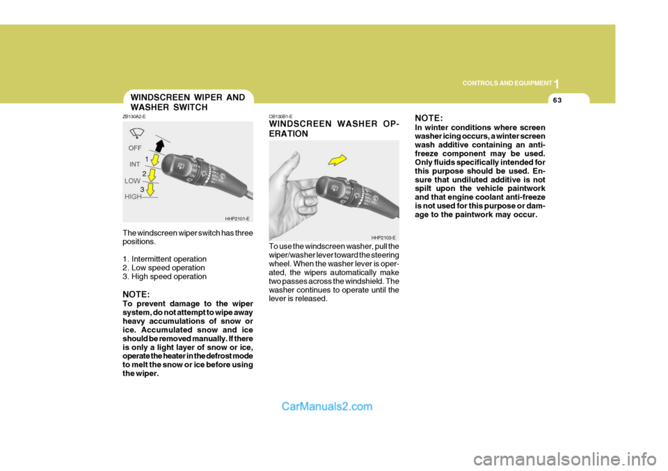
The windscreen wiper switch has three positions.
1. Intermittent operation
2. Low speed operation
3. High speed operation NOTE: To prevent damage to the wiper system, do not attempt to wipe awayheavy accumulations of snow or ice. Accumulated snow and ice should be removed manually. If thereis only a light layer of snow or ice, operate the heater in the defrost mode to melt the snow or ice before usingthe wiper.WINDSCREEN WIPER AND WASHER SWITCH
ZB130A2-E
HHP2101-E
1
OB130B1-E WINDSCREEN WASHER OP- ERATION To use the windscreen washer, pull the wiper/washer lever toward the steeringwheel. When the washer lever is oper- ated, the wipers automatically make two passes across the windshield. Thewasher continues to operate until the lever is released. NOTE: In winter conditions where screen washer icing occurs, a winter screen wash additive containing an anti-freeze component may be used. Only fluids specifically intended for this purpose should be used. En-sure that undiluted additive is not spilt upon the vehicle paintwork and that engine coolant anti-freezeis not used for this purpose or dam- age to the paintwork may occur.
HHP2103-E
2 3
Page 440 of 539
2
DRIVING YOUR HYUNDAI
27
!
YC200C3-A Trailer Brakes If your trailer is equipped with a braking system, make sure it conforms to fed-eral and/or local regulations and that it is properly installed and operating cor- rectly. NOTE: If you tow a trailer or vehicle, your car will require more frequent main-tenance due to the additional load. See Maintenance Under Severe Usage Conditions" on page 5-6. CAUTION:
o Never connect a trailer brake sys- tem directly to the vehicle brakesystem.
o When towing a trailer on steep grades (in excess of 12%) payclose attention to the engine cool-ant temperature gauge to ensure the engine does not overheat. If the needle of the coolant tem-perature gauge moves across the dial towards "H" (HOT), pull over and stop as soon as it is safe todo so, and allow the engine to idle until it cools down. You may proceed once the engine hascooled sufficiently. YC200D2-E Safety Cables Should the towbar connection between your car and the trailer or vehicle youare towing fail, the trailer or vehicle could wander dangerously across other lanes of traffic and ultimately leave theroadway. To eliminate this potentially dangerous situation, safety cables, attached between your car and thetrailer or towed vehicle, are required.
Page 448 of 539

3 IN CASE OF EMERGENCY
4
!
1. Ensure that the booster battery is 12
volt type. If the booster battery is installed in another vehicle, ensure that the two vehicles are not touch- ing.
2. Turn off all unnecessary electrical equipment in both vehicles.
3. Ensure that the engine of the ve- hicle providing the jump start is run- ning prior to connection of the jump cables.
4. Connect the red jump cable to the positive (+) terminal of the boosterbattery and the other end to thepositive (+) terminal of the dis- charged battery.
5. Attach the black jump cable to the negative (-) terminal of the boosterbattery, and the other end to a ground point within the engine compartmentof the vehicle with the flat bat-tery. Do not connect to the negative bat- tery terminal of the flat battery sincesparks may be generated with the subsequent risk of explosion.
6. Raise the booster vehicle engine speed to 2,000 r.p.m. and start theengine of the vehicle with the flat battery. 7. Switch "ON" the main beam
headlamps before carefully remov-ing the jumper cables in the reverse order of attachment. Once the jumper cables have been removed,switch "OFF" the main beam headlamps.
CAUTION:
If the jump cable is incorrectly in- stalled, damage to the vehicle elec- trical system may occur, in particu- lar the electronic components suchas the Fuel Injection system com- puter and the Automatic transmis- sion computer. The battery mustnever be disconnected whilst the engine is running.
IF THE ENGINE OVERHEATS
HPD040A2-E If the temperature gauge indicates overheating:
1. Pull off the road and stop as soon as it is safe to do so.
2. Place the gear selector lever in "P"
(automatic), or neutral (manual trans- mission) and set the parking brake. If the air conditioning is on, turn it off.
3. If coolant is running out under the car or steam is coming out from underthe bonnet, stop the engine. Do not open the bonnet until the coolant hasstopped running or the steaming has stopped. If there is no visible loss of coolant and no steam, leave theengine running and check to be sure the engine cooling fan is operating. If the fan is not running, turn theengine off.
4. Check to see if the water pump drive
belt is missing. If it is not missing,check to see that it is tight. If the drive belt seems to be satisfactory, check for coolant leaking from theradiator, hoses or under the car. (If the air conditioning had been in use, it is normal for cold water to bedraining from it).
Page 449 of 539
3
IN CASE OF EMERGENCY
5
!
!
!WARNING:
Whilst the engine is running, keep hands and clothing away from mov- ing parts such as the fan and drive belts to prevent injury.
WARNING (Diesel only):
Never work on injection system withengine running or within 30 seconds after shutting off engine. High pres- sure pump, rail, injectors and highpressure pipes are subject to high pressure even after the engine stopped. The fuel jet produced byfuel leaks may cause serious in- jury, if it touch the body. People using pacemakers should not movethan 30cm closer to the ECU or wiring harness within the engine room while engine is running, sincethe high currents in the Common Rail system produce considerable magnetic fields. 5. If the water pump drive belt is broken
or coolant is leaking out, stop theengine immediately and call the near- est Hyundai dealer for assistance.
WARNING:
Do not remove the radiator cap when the engine is hot since steam andboiling water may be ejected from the radiator resulting in burns or scalding.
6. If the cause of the overheating can- not be found, wait until the engine temperature has returned to normal.Then, if coolant has been lost, care- fully remove the radiator cap and add water to bring the fluid level in thereservoir(page 6-10) up to the base of the radiator fill opening. Fill the coolant expansion tank to the half-way mark.
7. Proceed with caution until it is estab-
lished that the engine is operatingnormally. If the engine overheats repeatedly, the advice of a Hyundai dealer should be sought.! CAUTION:
Serious loss of coolant indicates there is a leak in the cooling system and this should be checked as soon as possible by a Hyundai dealer.
Page 472 of 539
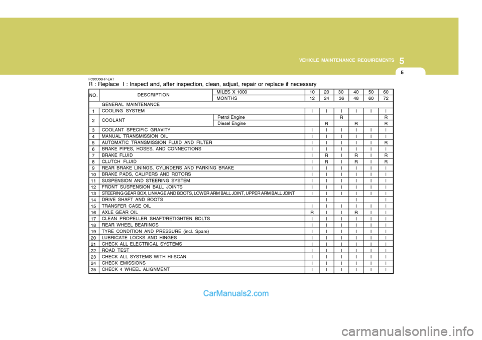
5
VEHICLE MAINTENANCE REQUIREMENTS
5
20 24
I
R II I I
RR II I I I I I I I I I I I I I I I
F030C06HP-EAT R : Replace I : Inspect and, after inspection, clean, adjust, repair or replace if necessary
DESCRIPTION
GENERAL MAINTENANCE COOLING SYSTEM COOLANT COOLANT SPECIFIC GRAVITY MANUAL TRANSMISSION OIL AUTOMATIC TRANSMISSION FLUID AND FILTER BRAKE PIPES, HOSES, AND CONNECTIONS BRAKE FLUID CLUTCH FLUID
REAR BRAKE LININGS, CYLINDERS AND PARKING BRAKE BRAKE PADS, CALIPERS AND ROTORS SUSPENSION AND STEERING SYSTEM FRONT SUSPENSION BALL JOINTS
STEERING GEAR BOX, LINKAGE AND BOOTS, LOWER ARM BALL JOINT, UPPER ARM BALL JOINT
DRIVE SHAFT AND BOOTS TRANSFER CASE OIL AXLE GEAR OIL CLEAN PROPELLER SHAFT/RETIGHTEN BOLTS REAR WHEEL BEARINGS TYRE CONDITION AND PRESSURE (incl. Spare) LUBRICATE LOCKS AND HINGES CHECK ALL ELECTRICAL SYSTEMS ROAD TEST CHECK ALL SYSTEMS WITH HI-SCAN CHECK EMISSIONS CHECK 4 WHEEL ALIGNMENT
NO.
1
2 3 4 5 6 7 8 9
1011 12 13 14 15 16 17 18 19 20 21 22 23 24 25
60 72
I
RR II
R
I
RR II I I I I I I I I I I I I I I I
50 60
I I I I I I I I I I I I I I I I I I I I I I I
40 48
I
R II I I
RR II I I I I I
R I I I I I I I I I
30
36
I
R
I I I I I I I I I I I I I I I I I I I I I I
10 12
I I I I I I I I I I I I I
R I I I I I I I I I
MILES X 1000MONTHS
Petrol Engine Diesel Engine