2005 Hyundai Terracan engine coolant
[x] Cancel search: engine coolantPage 488 of 539
6
OWNER MAINTENANCE
11
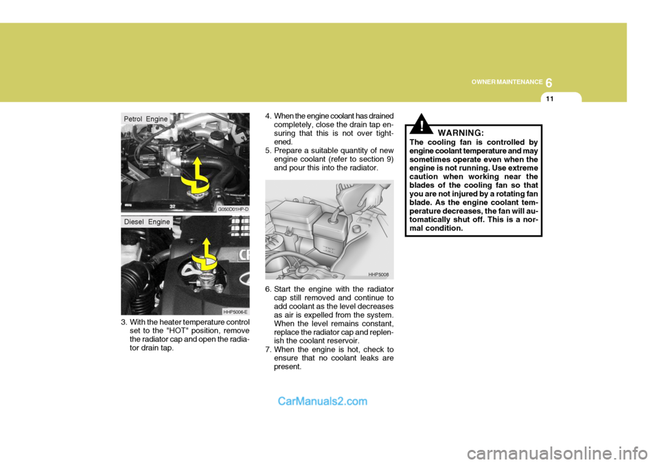
3. With the heater temperature control set to the "HOT" position, remove the radiator cap and open the radia-tor drain tap. 4. When the engine coolant has drained
completely, close the drain tap en-suring that this is not over tight- ened.
5. Prepare a suitable quantity of new engine coolant (refer to section 9)and pour this into the radiator.
6. Start the engine with the radiator cap still removed and continue to add coolant as the level decreases as air is expelled from the system. When the level remains constant,replace the radiator cap and replen- ish the coolant reservoir.
7. When the engine is hot, check to ensure that no coolant leaks are present.
G050D01HP-D
HHP5006-E
HHP5008
Petrol EngineDiesel Engine
!WARNING:
The cooling fan is controlled by engine coolant temperature and maysometimes operate even when the engine is not running. Use extreme caution when working near theblades of the cooling fan so that you are not injured by a rotating fan blade. As the engine coolant tem-perature decreases, the fan will au- tomatically shut off. This is a nor- mal condition.
Page 493 of 539
6 OWNER MAINTENANCE
16
!!
CAUTION:
Engine coolant anti freeze must not be used in the windscreen washersystem since damage to the paintwork may result. Undiluted windscreen washer addi- tive must not be allowed to come into contact with the paintwork. If spillage occurs, flush the affectedarea immediately with water. Do not operate the windscreen washer for more than 15 seconds continu- ously or when the reservoir is empty since damage to the washerpump will result. The transmission lubricant should be
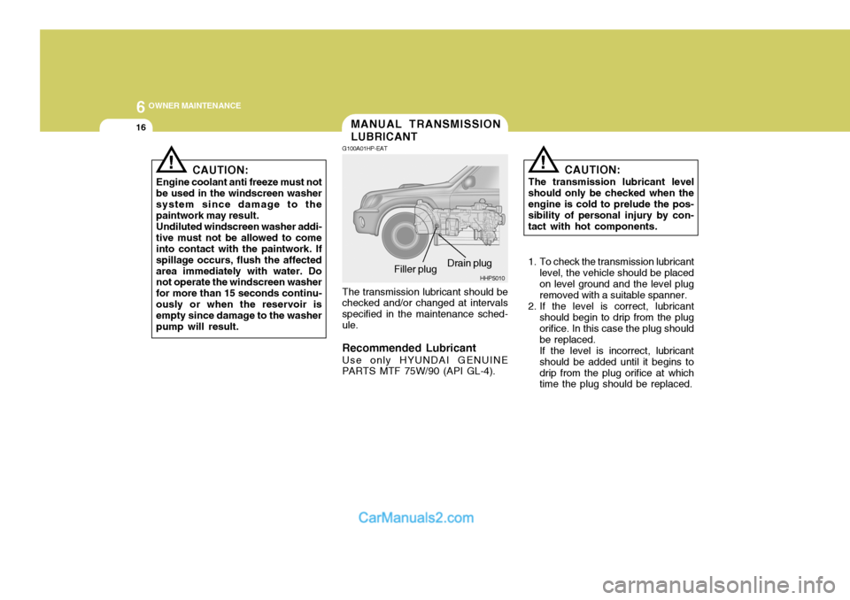
checked and/or changed at intervalsspecified in the maintenance sched-ule. Recommended Lubricant
Use only HYUNDAI GENUINE
PARTS MTF 75W/90 (API GL-4). CAUTION:
The transmission lubricant level
should only be checked when the engine is cold to prelude the pos- sibility of personal injury by con-tact with hot components.
1. To check the transmission lubricant level, the vehicle should be placed on level ground and the level plug removed with a suitable spanner.
2. If the level is correct, lubricant should begin to drip from the plug orifice. In this case the plug shouldbe replaced.If the level is incorrect, lubricantshould be added until it begins todrip from the plug orifice at which time the plug should be replaced.
MANUAL TRANSMISSION LUBRICANT
G100A01HP-EAT
Drain plug
HHP5010
Filler plug
Page 505 of 539
6 OWNER MAINTENANCE
28
!WARNING:
The cooling fan is controlled by engine coolant temperature and may sometimes operate even when the engine is not running. Do not touchthe radiator fan until it is completely stopped. As the coolant temperature de- creases the fan will automatically shut off. This is a normal condi-tion.
Checking Engine Cooling Fan The engine cooling fan should auto-matically come on if the engine cool- ant temperature is high.
Checking Condenser Cooling Fan The condenser cooling fan (in front of the condenser) should come on auto- matically whenever the air conditioner is in operation.
If any electrolyte gets into your eyes, flush your eyes with clean water for at least 15 minutes and get imme-diate medical attention. If possible, continue to apply water with a sponge orcloth until medical atten- tion is received. If electrolyte gets on your skin, thoroughly wash the contacted area. If you feel a pain or a burn- ing sensation, get medical attention immediately.Wear eye protection whencharging or working near abattery.Always provide ventilationwhen working in an en- closed space.o When lifting a plastic-cased bat- tery, excessive pressure on the case may cause battery acid to leak, resulting in personal injury.Lift with a battery carrier or with your hands on opposite corners.
o Never attempt to charge the bat- tery when the battery cables are connected.
o The electrical ignition system works with high voltage. Never touch these components with the engine running or the ignition switched on.
CHECKING ELECTRIC COOLING FANS
YG210A1-E
Page 510 of 539
6
OWNER MAINTENANCE
33
And then, draw a parallel line at 1.50 in. (38 mm) under the horizontal line incase of adjusting the low beam or at 0.83 in. (21 mm) under the horizontal line in case of adjusting the high beam.
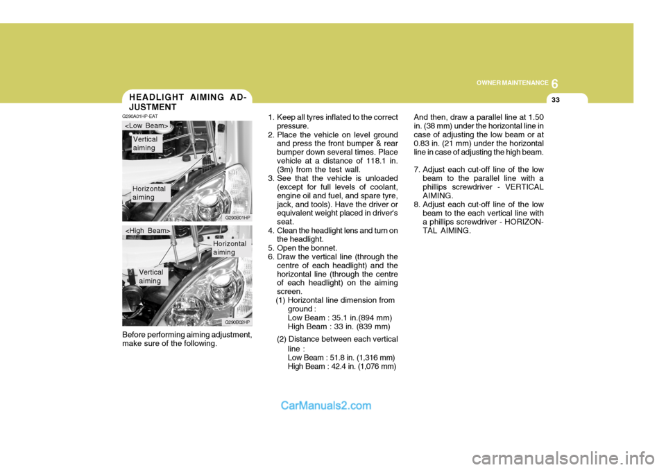
7. Adjust each cut-off line of the low beam to the parallel line with a phillips screwdriver - VERTICAL AIMING.
8. Adjust each cut-off line of the low beam to the each vertical line witha phillips screwdriver - HORIZON-TAL AIMING.
Before performing aiming adjustment,make sure of the following.HEADLIGHT AIMING AD- JUSTMENT
G290A01HP-EAT
1. Keep all tyres inflated to the correct
pressure.
2. Place the vehicle on level ground and press the front bumper & rear bumper down several times. Placevehicle at a distance of 118.1 in. (3m) from the test wall.
3. See that the vehicle is unloaded (except for full levels of coolant, engine oil and fuel, and spare tyre,jack, and tools). Have the driver or equivalent weight placed in driver's seat.
4. Clean the headlight lens and turn on the headlight.
5. Open the bonnet.
6. Draw the vertical line (through the centre of each headlight) and thehorizontal line (through the centre of each headlight) on the aiming screen.
(1) Horizontal line dimension from
Horizontal aiming
Vertical aiming
G290B01HP
G290B02HP
Horizontal aiming
Vertical aiming
ground : Low Beam : 35.1 in.(894 mm) High Beam : 33 in. (839 mm)
(2) Distance between each vertical line :Low Beam : 51.8 in. (1,316 mm) High Beam : 42.4 in. (1,076 mm)
Page 520 of 539
7
EMISSION CONTROL SYSTEMS
3
DH010B1-E
1. Crankcase Emission Control System ; For a Petrol Engine
The positive crankcase ventilation
system is employed to prevent air pollution caused by blow-by gases being emitted from the crankcase.
This system supplies fresh air to the
crankcase through the air cleaner.Inside the crankcase, the fresh airmixes with blow-by gases, then passes through the PCV valve into the intake system.
ZH010C1-E
2. Evaporative Emission Control System ; For a Petrol Engine
The Evaporative Emission Control
System is designed to prevent fuel vapors from escaping into the atmo-sphere. Canister
Whilst the engine is inoperative, fuel
vapors generated inside the fuel tankare absorbed and stored in the canis-ter. When the engine is running, the fuel vapors absorbed in the canister are drawn into the induction systemthrough the purge control solenoid valve. Purge Control Solenoid Valve
The purge control solenoid valve is
controlled by the ECU; when the en- gine coolant temperature is low, and during idling, it closes, so that evapo- rated fuel is not taken into the surgetank. After engine warm-up, during ordinary driving, it opens to introduce evaporated fuel to the surge tank.
SH010D1-E
3. Exhaust Emission Control System
The exhaust emission control system
is a highly effective system which controls exhaust emission while main- taining good vehicle performance.
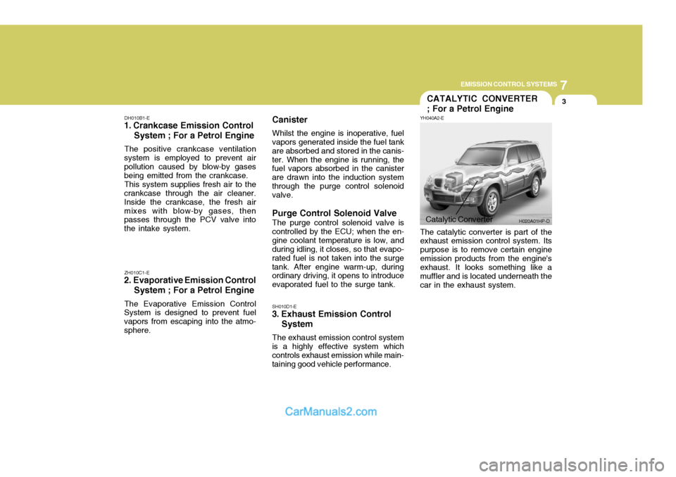
Catalytic Converter H020A01HP-D
CATALYTIC CONVERTER ; For a Petrol Engine
YH040A2-E The catalytic converter is part of the exhaust emission control system. Its purpose is to remove certain engineemission products from the engine's exhaust. It looks something like a muffler and is located underneath thecar in the exhaust system.
Page 535 of 539
10INDEX
2
A Air Cleaner Filter ........................................................ 6-13
Air Conditioning
Maintenance ........................................................... 6-21
Operation ................................................................ 1-96
Switch ..................................................................... 1-96
Airbag ........................................................................ 1-40
Antenna ................................................................... 1-107
Apperance Care ........................................................... 4-1
Ashtray ...................................................................... 1-68
Automatic Heating and Cooling Control System ........ 1-98
BBattery ....................................................................... 6-27
Bi-Level Heating ........................................................ 1-94
Bonnet Release ......................................................... 1-83
Brake
Anti-lock system (ABS) .......................................... 2-21
Brake system checking .......................................... 6-19
Effective braking ..................................................... 2-22
Fluid ........................................................................ 6-19
Pedal clearance ...................................................... 6-24
Pedal free-play ........................................................ 6-23
CCatalytic Converter ...................................................... 7-3
Centre Console Compartment ....................................1-74
Child Restraint System .............................................. 1-31
Child-Proof Rear Door Lock ....................................... 1-10Cigar Lighter
.............................................................. 1-67
Clock ......................................................................... 1-66
Clutch
Checking fluid ......................................................... 6-20
Pedal free-play ........................................................ 6-23
Cooling Fans ............................................................. 6-28
Cruise Control ............................................................ 1-86
DDaily Operating Checks ............................................... 6-4
Defrosting/Defogging .................................................. 1-95
Door Central door locks .................................................. 1-11
Locking, unlocking front door with a key .................. 1-9
Drink Holder ............................................................... 1-69
Drive Belts ................................................................. 6-24
Driving
Driving for economy ............................................... 2-23
Smooth corneri ng .................................................... 2-24
Winter motoring ...................................................... 2-24
E EGR system ................................................................ 7-5Emission Contro l System ............................................ 7-1
Engine
Before starting the engine ........................................ 2-3 Compartment (3.5 V6) .............................................. 6-2
Compartment (2.9 CRDi) ........................................... 6-3
Coolant ..................................................................... 6-9
Page 536 of 539

10
INDEX
3
Coolant temperature gauge .....................................1-57
If the engine overheats ............................................. 3-4
Number ..................................................................... 8-2
Oil ............................................................................. 6-4 Starting ..................................................................... 2-5
Engine Exhaust Can Be Dangerous! ........................... 2-2
F Fan Speed Control ................. .........................1-90, 1-101
Fog Light Switch Front ....................................................................... 1-62
Rear ........................................................................ 1-62
Four-Wheel Drive(4WD) ............................................. 2-14
Front Door Edge Warning Light ................................. 1-84
Front Seats
Adjustable head restraints ...................................... 1-17
Adjusting seatback angle ....................................... 1-17
Driver's seat lumbar support control .......................1-18
Seat adjust ment ..................................................... 1-16
Seat cushion height adjustment ............................. 1-19
Seat fore/aft adjustment ......................................... 1-16
Fuel Capacity ................................................................... 9-2
Gauge ..................................................................... 1-57
Recommendations .................................................... 1-2
Fuel-Filler Flap Remote release ........................................................ 1-2
Full-time 4WD Operation ............................................ 2-17
Fusible Links ............................................................. 6-25G
Glove Box ................................................................. 1-73
H Hatchback Door ......................................................... 1-78
Hazard Warning System ............................................ 1-65
Headlight Aiming Adjustment..................................... 6-33
Headlight Bulbs Replacement ....................................6-31
Headlight Leveling Device S ystem ............................1-85
Heated Front/Rear Window .. ......................................1-65
Heating and Cooling Control ......................................1-89
Heating and Ventilation
Air flow control ............................................. 1-91, 1-102
Air intake control ......................................... 1-91, 1-101
Defrosting/Defogging ............................................... 1-95
Fan speed control ........................................ 1-90, 1-101
Temperature control ................................................ 1-83
High-Mounted Rear Stop Light ...................................1-82
Horn ........................................................................... 1-84
I Ignition Switch ............................................................. 2-3
Illuminated ignition switch ......................................... 1-8
Immobiliser System ..................................................... 1-5
Indicator and Warning Lights ..................................... 1-50
Instrument Cluster and Indicator Lights ..................... 1-46
Interior Light ............................................................... 1-72
Interior Rearview Mirror .............................................. 1-77
Intermittent Wi pe Facility ........................................... 1-64