Page 57 of 407

1- 49
CONTROLS AND EQUIPMENTSB380A1-E PARKING BRAKE The parking brake must always be set when the vehicle is to be left unattended. When theparking brake is applied, and the ignition keyis at the "ON" position, the parking brakewarning light will be illuminated. Before drivingthe vehicle, the parking brake must be fullyreleased and the warning light extinguished.
o To set the parking brake, apply the foot brake and pull the parking brake lever up with the button depressed. Release thebutton when the brake is fully applied.
o To release the parking brake, apply the foot brake and pull up the parking brakelever slightly. Depress the button and lowerthe lever.
SB370A1-E
INTERIOR REAR VIEW MIRROR
The interior mirror is of the day/night type to
enable the glare of headlights from followingvehicles to be eliminated during night timedriving.
The tab located at the bottom of the mirror
should be set to the position nearest thewindscreen for normal day time driving, andflipped towards the rear of the vehicle toeliminate glare during night time driving. Toadjust the field of vision, the mirror may bemoved by hand upon the mounting.
NOTE:The mirror should always be adjusted prior
to setting the vehicle in motion.
B530A01FC-DB550A01FC
B520A01E
B550A01S-DAT
HIGH-MOUNTED REAR STOP LIGHT
In addition to the lower-mounted rear stop-
lights on either side of the car, the high
mounted rear stoplight in the centre of the rearwindow or inserted in the rear spoiler alsolights when the brakes are applied. CAUTION:
o Only use the power outlet when the engine is running. Remove the electri-cal appliance from the power outletwhen not in use. Failure to adhere tothis advice may result in a dischargedbattery after several hours.
o Do not use the power outlet to connect electric accessories or equipment otherthan those designed to operate on 12volts.
Page 58 of 407

CONTROLS AND EQUIPMENT
1- 50 B820A01FC-GAT ACCESSORY TRAY
HFC2071-D
B500D08O-EAT POWER OUTLET (Not all models)
HFC2042-D
These supply 12V electric power to operate
electric accessories or equipment only when the key is in the "ON" or "ACC" position. CAUTION:
o Only use the power outlet when the engine is running. Remove the electri-cal appliance from the power outletwhen not in use. Failure to adhere tothis advice may result in a dischargedbattery after several hours.
o Do not use the power outlet to connect electric accessories or equipment otherthan those designed to operate on 12volts.
o Some electronic devices can cause elec- tronic interference when plugged intothe power outlet. These devices maycause excessive audio noise and mal-functions in other electronic systemsor devices used in your vehicle.
The accessory tray may be opened by push-
ing the knob sidewards and releasing slowlyit.
It is used for storing small commodities.
B810A01FC-GAT FOLD-UP TRAY
For your convenience, it may be used as a table holding a book, cup or can. WARNING: To avoid the possibility of injury in case of an accident or a sudden stop, the fold-uptray should be place its original positionwhilst the vehicle is moving.
HFC2070
o Some electronic devices can cause elec-
tronic interference when plugged into the power outlet. These devices maycause excessive audio noise and mal-functions in other electronic systemsor devices used in your vehicle.
Page 59 of 407

1- 51
CONTROLS AND EQUIPMENT
B570A01FC-EAT
BONNET RELEASE
Pull the release lever inside the vehicle to
unlatch the bonnet. At the front of the vehicle, push the safety catch lever sidewards asshown and raise the bonnet by hand. Supportthe bonnet by means of the bonnet prop. Before closing the bonnet, ensure that the
prop is correctly stowed. Lower the bonnet byhand to a position of approximately 30cm fromthe closed position and allow the bonnet todrop. Do not attempt to close the bonnet bylowering the panel to the closed position andpressing upon the panel work since this mayresult in damage to the panel. CAUTION:Ensure that the bonnet prop has beenremoved prior to closing the bonnet. Al-ways check to ensure that the bonnet haslatched prior to setting the vehicle in mo-tion. WARNING: The bonnet prop must be correctly in- serted into the panel to prevent the possi-bility of injury arising from the bonnetfalling.
HFC2019
HFC2018-D
SB440A1-E
REMOTE FUEL FILLER FLAP
RELEASE (Not all models) The fuel filler flap may be opened from inside
the vehicle by pulling up on the fuel filler flap release.
NOTE: If the fuel filler flap will not open because
ice has formed around it, tap lightly or push on it to break the ice and release it.Do not lever the flap. If necessary, sprayaround the flap with an approved deicerfluid (do not use radiator anti-freeze) ormove the vehicle to a warm place andallow the ice to melt.
HFC2015-D
Page 60 of 407

CONTROLS AND EQUIPMENT
1- 52
B540A01FC-GAT
TAIL GATE
B540A01FC
WARNING: The tail gate should always be kept com-
pletely closed whilst the vehicle is in motion. If it is left open or ajar, poisonousexhaust gases may enter the car resultingin serious illness or death to the occu-pants. See additional warnings concerningexhaust gases on page 2-1.
o The tail gate can be locked or unlocked with a key.
o The tail gate is opened by pulling the outside handle up, raising the tail gate manually.
o To close, lower the tail gate, then press down on it until it is closed. To be sure thetail gate is fully closed, always try to pull itup again without using the outside handle. LOCK
UNLOCK
B540D03FC-DAT Luggage Net Some objects can be kept in the net in the luggage compartment.Use the luggage net on the floor or at the backof the luggage compartment to prevent theobjects from sliding. WARNING: Avoid eye injury. DO NOT overstretch. ALWAYS keep face and body out of recoilpath. DO NOT use when strap has visiblesigns of wear or damage. CAUTION: To prevent damage to the goods or the vehicle, care should be taken when carry-ing fragile or bulky objects in the trunk.
B540D01HP
WARNING: Fuel vapours are dangerous. Before refu- elling, turn off the engine and never allowsparks, lit cigarettes or open flames nearthe filler area. When releasing the fillercap, a small amount of residual pressuremay generate a slight hissing sound whichis not indicative of an abnormality. In theevent of the fuel filler cap requiring re-placement, only a Genuine Hyundai re-placement part should be used to preventfuel leakage.
HFC2016
Page 61 of 407

1- 53
CONTROLS AND EQUIPMENT
70 kg (154 lb)
EVENLY DISTRBUTED
HFC2106
B630A01FC-EAT
ROOF RACK (Not all models) If your Hyundai has a roof rack, you can load
things on top of your vehicle. Crossrails and fixing components to adapt the roof rack onyour vehicle may be obtained from an Hyundaiauthorised repairer.
CAUTION:
o The following specifications are recom- mended when loading cargo or luggage.
ROOF RACK
o Loading cargo or luggage above 70 kg (154 lb) on the roof rack may damage your vehicle. When you carry large objects, never let them hang over the rear or the sides ofyour vehicle.
o To prevent damage or loss of cargo as you are driving, check frequently tomake sure the luggage carrier and cargoare still securely fastened.
o Always drive your vehicle at a moderate speed.
o To use the roof rails as a roof rack, you must fit the roof rails with two or morecrossrails or equivalent before carryingcargo or lugguage on the roof.
o When crossrail is adapted, you can load items on the roof rack.
o Loading cargo or luggage over speci- fication on the roof rack may damagestability of your vehicle.
B650A01FC-DAT CARGO AREA COVER
B640A01FC
Nothing should be carried on top of the lug-
gage cover. Loose materials could result in injury to vehicle occupants during sudden brak- ing. B560B01O-GAT
Auto Fuel Cut Switch (Gasoline Engine)HFC4001
The auto fuel cut switch is located on the
driver's side of the engine compartment.
In the event of a collision or sudden impact,
the auto fuel cut device cuts off the fuel supply. If this device is activated, it must bereset by pressing in on the top of the switchbefore the engine can be restarted.
WARNING: Before resetting the auto fuel cut switch,
the fuel line should be checked for fuel leaks.
Page 62 of 407

CONTROLS AND EQUIPMENT
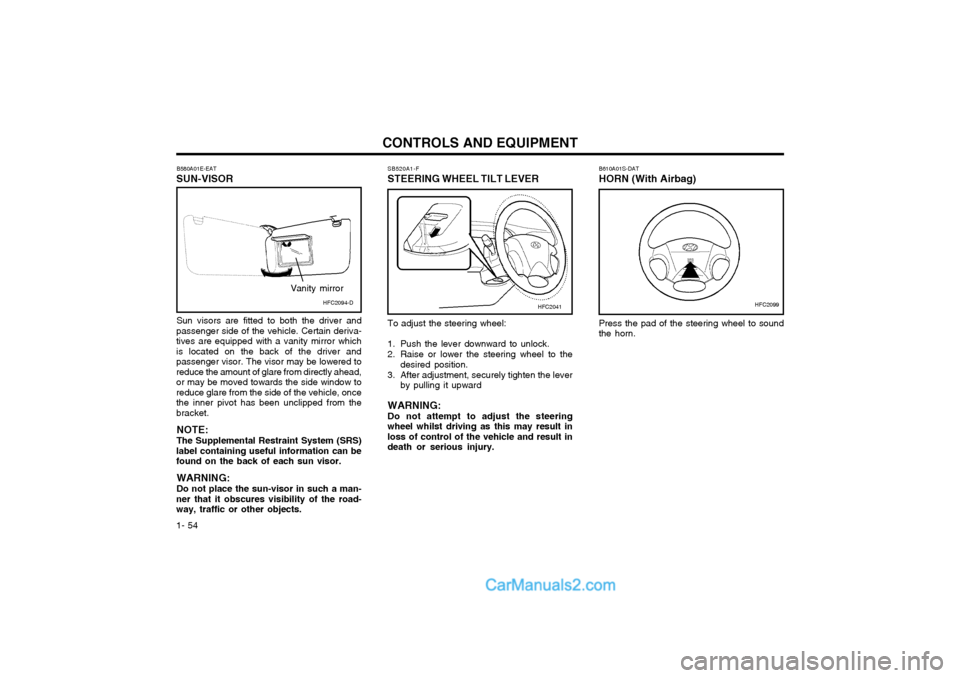
1- 54 B610A01S-DAT HORN (With Airbag) Press the pad of the steering wheel to sound the horn.
B580A01E-EAT
SUN-VISOR
Sun visors are fitted to both the driver and
passenger side of the vehicle. Certain deriva-tives are equipped with a vanity mirror whichis located on the back of the driver andpassenger visor. The visor may be lowered toreduce the amount of glare from directly ahead,or may be moved towards the side window toreduce glare from the side of the vehicle, oncethe inner pivot has been unclipped from thebracket.
NOTE: The Supplemental Restraint System (SRS)
label containing useful information can be found on the back of each sun visor.
WARNING: Do not place the sun-visor in such a man-
ner that it obscures visibility of the road- way, traffic or other objects. SB520A1-F
STEERING WHEEL TILT LEVER
HFC2099HFC2041HFC2094-D
Vanity mirror
To adjust the steering wheel:
1. Push the lever downward to unlock.
2. Raise or lower the steering wheel to the
desired position.
3. After adjustment, securely tighten the lever by pulling it upward
WARNING: Do not attempt to adjust the steeringwheel whilst driving as this may result inloss of control of the vehicle and result indeath or serious injury.
Page 63 of 407
1- 55
CONTROLS AND EQUIPMENT
B710A01Y-EAT Heating and Cooling Control (Not all models)
1. Side Ventilator
2. Centre Ventilator
3. Windscreen defrost Ventilator B710B01A-DAT
Centre Ventilator The centre ventilators are located in the middle
of the dashboard.
To change the direction of the air flow, turn
the control knob on the middle of the ventilator as desired. B710C01Y-AAT Side VentilatorThe side vent knobs control the amount of outside air entering the vehicle through theside vents. These vents can also be closed,so no air enters through the side vents. Tochange the direction of the air flow, turn thecontrol knobs as desired.
1 1
2
3 B710A01S-AAT VENTILATION To operate the ventilation system:
o Set the air intake control to "Fresh" mode
(
).
o To direct all intake air to the dashboard vents, set the air flow control to "Face".
o Adjust the fan speed control to the desired speed.
o Set the temperature control between "Cool" and "Warm".
HFC002-D
Page 64 of 407

CONTROLS AND EQUIPMENT
1- 56
B670A01FC-EAT HEATING AND VENTILATION ROTARY TYPE (Not all models)
B670A01FC
1
23
4
This model has four controls for the heating
and cooling system. They are:
1. Temperature control
2. Fan speed control
3. Air flow control
4. Air intake control B670C02FC-EAT
Air Intake Control
HFC2067
This is used to select fresh outside air or
recirculation inside air.
To change the air intake control mode, (Fresh
mode, Recirculation mode) push the control button.
FRESH MODE (
) : The indicator light on
the button goes off when the air intake control is in fresh mode.
RECIRCULATION MODE (
): The indica-
tor light on the button is illuminated when the air intake control is in recirculation mode.
With the "Fresh" mode selected, air enters the
vehicle from the outside and is heated orcooled according to the function selected.
With the "Recirculation" mode selected, air
from within the passenger compartment will bedrawn through the heating system and heatedor cooled according to the function selected.
B670B01FC-AAT
Fan Speed Control (Blower Control)
HFC2065
This is used to turn the blower fan on or off
and to select the fan speed.
This blower fan speed, and therefore the
volume of air delivered from the system, may be controlled manually by setting the blowercontrol between the "1" and "4" positions.
"1" the being lowest and "4" being the highest
fan speed.