2005 Hyundai Matrix lock
[x] Cancel search: lockPage 118 of 407

OWNER MAINTENANCE 6-11
6. Start the engine with the radiator cap still
removed and continue to add coolant as the level decreases as air is expelled fromthe system. When the level remains con-stant, replace the radiator cap and replen-ish the coolant reservoir.
7. When the engine is hot, check to ensure that no coolant leaks are present.
WARNING: The cooling fan is controlled by engine coolant temperature and may sometimesoperate even when the engine is not run-ning. Use extreme caution when workingnear the blades of the cooling fan so thatyou are not injured by a rotating fanblade. As the engine coolant temperaturedecreases, the fan will automatically shutoff. This is a normal condition.
G050D02FCSSA6060B
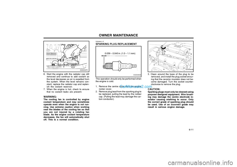
3. Clean around the base of the plug to be removed, and install the plug socket ensur- ing that the ceramic insulator does not be-come damaged. Turn the socket counter-clockwise to remove the plug.
CAUTION: Sparking plugs must only be cleaned using purpose designed equipment. Wire brush-ing may damage the centre electrode in-sulator causing misfiring to occur. Onlythe correct grade of sparking plug shouldbe used. Use of an incorrect grade mayresult in serious engine damage.
SG060A1-E
SPARKING PLUG REPLACEMENT
SSA6060A
0.039 ~ 0.043 in. (1.0 ~ 1.1 mm)
This operation should only be performed when
the engine is cold.
1. Remove the centre cover from the engine rocker cover.
2. Remove plug lead from the sparking plug to be replaced, pulling the lead by the rubber cap. (Pulling the lead may damage the car-bon conductor).
Page 124 of 407

OWNER MAINTENANCE 6-17
WARNING: Brake fluid is hygroscopic and should never be stored in an unsealed container.The presence of water in the brakingsystem will cause vapour locks and in-crease the possibility of brake fade alongwith promoting corrosion within the brak-ing system. The brake fluid must bechanged at the specified time or mileageinterval to ensure continued safe opera-tion of the system. Brake fluid will causerapid and serious damage to paintwork. Ifaccidental spillage occurs, the affectedarea must be rinsed with water immedi-ately. Do not allow brake fluid to comeinto contact with the eyes or to be in-gested and ensure that fluid is safelystored away form the reach of children.
G120D02FC
Diesel engineSG130A1-C
CHECKING THE CLUTCH FLUID To Check the Clutch Fluid
SG130B2-E
Adding Fluid
Recommended brake fluid conforming to DOT 3
or DOT 4 should be used. The reservoir cap must be fully tightened to avoid contaminationfrom foreign matter or moisture.
CAUTION: Brake fluid is hygroscopic and should
never be stored in an unsealed container. Do not allow petroleum base fluid tocontaminate the brake fluid since damageto the rubber seals of the system mayresult.
WARNING: Brake fluid will cause rapid and serious
damage to paintwork. If accidental spillage occurs, the affected area must be rinsedwith water immediately. Do not allow brakefluid to come into contact with the eyes or tobe ingested and ensure that fluid is safelystored away form the reach of children.
HFC5005
Petrol engine
The clutch fluid level in the master cylinder
should be checked when performing other un- der bonnet checks. The system should bechecked for leakage at the same time.
G120D02FC
Diesel engine Ensure that the clutch fluid level is always
between the "MAX" and "MIN" level markings on the fluid reservoir. Fill as required. Fluidloss indicates a leak in the clutch systemwhich should be inspected and repaired im-mediately.
Page 135 of 407

OWNER MAINTENANCE
6-28
G200C01FC-EAT
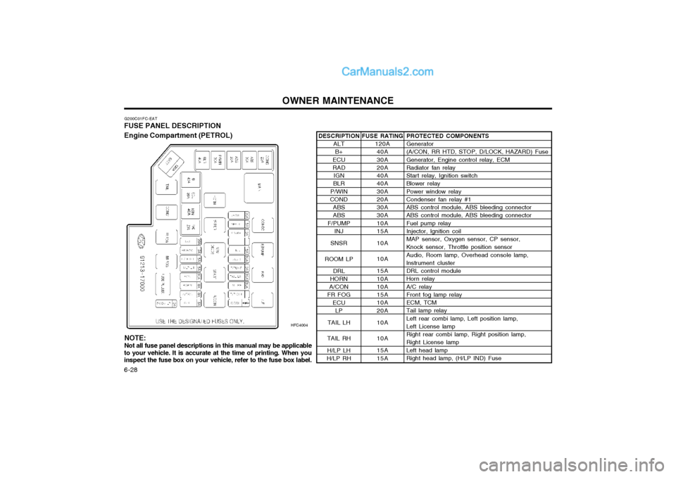
FUSE PANEL DESCRIPTION Engine Compartment (PETROL)
HFC4004PROTECTED COMPONENTS Generator (A/CON, RR HTD, STOP, D/LOCK, HAZARD) Fuse Generator, Engine control relay, ECM Radiator fan relay Start relay, Ignition switch Blower relay Power window relay Condenser fan relay #1 ABS control module, ABS bleeding connector ABS control module, ABS bleeding connector Fuel pump relay Injector, lgnition coil MAP sensor, Oxygen sensor, CP sensor, Knock sensor, Throttle position sensor Audio, Room lamp, Overhead console lamp, lnstrument cluster DRL control module Horn relay A/C relay Front fog lamp relay ECM, TCM Tail lamp relay Left rear combi lamp, Left position lamp, Left License lamp Right rear combi lamp, Right position lamp, Right License lamp Left head lamp Right head lamp, (H/LP IND) Fuse
FUSE RATING
120A40A 30A 20A 40A 40A 30A 20A 30A 30A 10A 15A 10A 10A 15A 10A 10A 15A 10A 20A 10A 10A 15A 15A
DESCRIPTION
ALTB+
ECU RAD IGN
BLR
P/WIN
COND
ABSABS
F/PUMP INJ
SNSR
ROOM LP DRL
HORN
A/CON
FR FOG
ECULP
TAIL LH
TAIL RH H/LP LH
H/LP RH
NOTE: Not all fuse panel descriptions in this manual may be applicable
to your vehicle. It is accurate at the time of printing. When you inspect the fuse box on your vehicle, refer to the fuse box label.
Page 137 of 407

OWNER MAINTENANCE
6-30
PROTECTED COMPONENTS
Generator (A/CON, RR HTD, STOP, D/LOCK, HAZARD) Fuse, DeicerGenerator, Engine control relay, ECMRadiator fan relay Start relay, Ignition switch Blower relayPower window relayCondenser fan relay #1ABS control module, ABS bleeding connectorABS control module, ABS bleeding connector Fuel pump relay ECM No.5 (Batt+)ECM No.4 (Batt+), Stop lamp switch, PTC heater relay #1Glow plug relay, Assistor heater relay 1/2, Stop lamp switch,TDC sensor, EGR act, Throttle plate act, VGT vacuum Audio, Room lamp, Overhead console lamp, lnstrument cluster, ETACM, Luggage lamp DRL control moduleHorn relayA/C relayFront fog lamp relayECM, TCM Tail lamp relay Left rear combi lamp, Left position lamp, Left License lampRight rear combi lamp, Right position lamp, Right License lampLeft head lampRight head lamp, (H/LP IND) FusePTC heater relay #1 GLOW relay PTC heater relay #2FFHS relayPTC heater relay #3
FUSE RATING
140A40A 30A 30A40A40A30A30A 30A 30A10A30A10A 15A10A 15A10A 10A 15A10A20A10A10A 15A 15A40A80A40A30A 40A
ALT
B+
ECU RAD
IGN
BLR
P/WIN COND ABSABS
F/PUMP ECUECU
SNSR
ROOM LP DRL
HORN
A/CON
FR FOG ECULP
TAIL LH
TAIL RH H/LP LH
H/LP RH
PTC HTR 1 GLOW
PTC HTR 2 FFHS
PTC HTR 3
FUSE
FUSIBLE LINK DESCRIPTION
Page 138 of 407

OWNER MAINTENANCE 6-31
DESCRIPTION
H/LP IND
HTD IND
A/CON
RR HTD
STOP
D/LOCK
HAZARD AUDIO
C/LIGHT A/B
A/B IND
T/SIG
ECU
ETACS
RR WPR START
FRT WPR S/HTD
P/OUTLET
IG2
O/S MRR
G200D01FC-GAT
Inner Panel
G200D01FC-D
PROTECTED COMPONENTS Head lamp indicator Defogger relay, Left(Right) outside mirror motor, Rear window motor A/C Switch Defogger relay Stop lamp switch, Power window relay Door lock(unlock) relay, ETACM, Sunroof relay Burglar alarm relay, Hazard relay Audio Cigarette lighter SRS control module SRS IND. Hazard switch, Seat belt timer, Instrument cluster, ABS control module, Pre-excitation resistor, Washer motor ECM, Vehicle speed sensor, TCM, Ignition coil ETACM, A/T Shift lever Rear wiper motor, Rear wiper relay Start relay Wiper relay, Washer motor, Wiper & Defogger timer Left (Right) front seat warmer switch Front (Rear) power outlet ETACM, Power window relay, Defogger relay, Sunroof relay Head lamp relay, Blower relay Outside mirror switch, Rear fog lamp relay
FUSE RATING
10A 10A 10A 30A 10A 15A 10A 10A 15A 10A 10A 10A 15A 10A 10A 10A 20A 15A 25A 10A 10A
Page 140 of 407

EMISSION CONTROL SYSTEM
7-2
It is of the utmost importance that the following information is read and understood by thevehicle operator in order to prevent operationalproblems arising from damage to the catalyst.Damage to the catalyst will result if contamina-tion occurs through the use of leaded fuel.Whilst the vehicle is fitted with a reduced diam-eter filler neck to prevent charging of the fueltank with a leaded fuel pump nozzle, it ispossible that the use of funnels or jerry cans willpermit leaded fuel to be introduced into the fueltank.The catalyst is intolerant of unburnt fuel andtherefore if an engine misfire condition exists,damage to the catalyst will occur. It is impera-tive that if a misfire condition develops, thevehicle is immediately presented to a Hyundaiauthorised repairer for rectification. Similarly,the practice of certain ignition system diagno-sis procedures which involve inducing a misfire(cylinder power balance tests for example)may result in catalyst damage.For these reasons, it is advisable that theexhaust gas emission be tested at each routineservice with a gas analyzer having a Hydrocar-bon measuring facility to ensure continuedreliability of the catalyst.Push or tow starting of the vehicle is to beavoided since unburnt fuel may be enter thecatalyst and result in damage. (Note, it isimpossible to push or tow start a Hyundaimodel equipped with fuel injection since thefuel pump safety interlock will prevent the pumpfrom operating under these conditions).
Operation of the catalyst involves extremelyhigh temperatures being attained within thecatalytic convertor, and although the convertoris fitted with heat shields, it is important that thevehicle is not parked over combustible or vola-tile material which may result in fire.If the above precautions are not adhered to andthe catalyst becomes inoperative, the resultantincrease in core temperature will result in a"melt down" where the catalyst core will meltand subsequently may block the exhaust sys-tem.Due to the fragile nature of the catalyst ele-ment, it is important that damage does notoccur when the vehicle is raised by means of agarage jack. Care must also be exercised toavoid driving over road hazards or debris whichmay cause damage to the catalyst element. H020D01S-GAT ; For a diesel engineAll Hyundai vehicles are equipped with oxida- tion type catalytic converter to reduce the car-bon monoxide, hydrocarbons and particulatecontained in the exhaust gas.
H020C01S-GAT EGR SYSTEM ; For a diesel engine This system helps control oxides of nitrogen by recirculating a part of the exhaust gas into theengine.
Page 141 of 407

CONSUMER INFORMATION 8-1
SI010B1-E
Engine Number
SI000A1-E
8. CONSUMER
INFORMATION
I010A01FC-EAT
VEHICLE IDENTIFICATION
NUMBER (VIN) The vehicle identification number (VIN) is
unique to each individual vehicle and is the number (sometimes referred to as chassisnumber) used upon the vehicle registrationdocument to identify the vehicle.
It can be found on the identification plate
attached to apron panel located on the driver'sside of the engine compartment. The engine number is stamped on the engine
block as shown in the drawing. I030A01FC-EAT
TYRE PRESSURES
In modern high-speed motoring, correct tyre
pressures are vitally important. Incorrect tyrepressures can affect vehicle safety by caus-ing reduced adhesion, steering response andtyre failure through overheating. The tyrepressure must only be checked when thetyres are cold. The correct tyre pressuresare indicated on the label affixed to the driver'sside "C" piller outer panel and below.
Diesel engine
I010B02B8
HFC6001
EADA010C
Petrol engine
5.5Jx14 5.5Jx15 6.0Jx15 3.5Jx153.5Jx15
TYRE
SIZE
RIM
SIZE PRESSURE, kPa (PSI)
185/65R14195/55R15 205/55R15
T115/70D15 T115/70R15 REAR
210(30)210(30)210(30)420(60)420(60) FRONT
250(36)250(36) 250(36) 420(60)420(60)
UP TO 2
PERSONS UP TO
MAX. LOAD
REAR
250(36)250(36) 250(36) 420(60)420(60)
FRONT210(30)210(30)210(30) 420(60) 420(60)
I030A01FC-D
Page 147 of 407

INDEX10-1
A ACCESSORY TRAY
........................................................................ 1-50
AIR CONDITIONING SWITCH ........................................................ 1-60
AIR CONDITIONING SYSTEM MAINTENANCE ...........................6-18
AIR CLEANER ELEMENT REPLACEMENT ..................................6-12
ANTENNA ......................................................................................... 1-64
ANTI-THEFT ALARM SYSTEM .... .......................................... 1-5 ~ 1-7
AUTO FUEL CUT SWITCH ............................................................. 1-53
AUTOMATIC TRANSAXLE ............................................................... 2-6
AUTOMATIC TRANSAXLE FLUID ................................................ 6-14
B BATTERY MAINTENANCE ............................................................. 6-21
BEFORE STARTING THE ENGINE ................................................. 2-2
BLEEDING THE FUEL SYSTEM ....................................................6-23
BONNET RELEASE ......................................................................... 1-51
BRAKE PEDAL FREEPLAY .................................... ........................ 6-19
BRAKE TRACTION CONTROL SYSTEM ................... ................... 2-10
BRAKE SYSTEM CHECKING ........................................................ 6-16CCARE OF SEAT
BELTS ................................................................. 1-14
CARGO AREA COVER ................................................................... 1-53
CATALYTIC CONVERTOR OPERATING PRECAUTIONS ............. 7-1
CENTRE VENTILATOR ................................................................... 1-55
CENTRAL DOOR LOCKS ................................................................. 1-5
CHANGING A FLAT TYRE ............................................................... 3-4
CHECKING THE CLUTCH FLUID.................................................. 6-17
CHILD-PROOF REAR DOOR LOCK ................................................ 1-4
CHILD RESTRAINT SYSTEM ............................................. 1-17 ~ 1-22
CIGAR LIGHTER ............................................................................. 1-42
CLUTCH PEDAL FREEPLAY ......................................................... 6-19
COMBINATION IGNITION SWITCH AND STEERING LOCK ........ 2-2
COOLANT TEMPERATURE GAUGE .............................................1-35
D DAILY OPERATING CHECKS .......................................................... 6-4
DIGITAL CLOCK .............................................................................. 1-42
DOOR LOCKS ................................................................................... 1-3
DOOR WINDOWS ............................................................................. 1-7 DRINK HOLDER .............................................................................. 1-43
DRIVE BELTS .................................................................................. 6-20
DRIVING FOR ECONOMY ............................................................. 2-11
JK000A1-A 10. INDEX
10