Page 185 of 219
6
DO-IT-YOURSELF MAINTENANCE
30
2. Replace with a new bulb.
HLC5020
G270H01A-AATInterior Light1. Remove the cover with a flat-head screw-
driver.
HLC5019
Page 186 of 219
6
DO-IT-YOURSELF MAINTENANCE
31
BULB WATTAGES
Part Name
Front Position Light
Headlight (High/Low)
Front Turn Signal Light
Interior Light (Map Light) (If Installed)
Interior Light
Front Fog Light (If Installed)
Front Side Marker LightNo.
8
9
10
11
12
G280A03A-AAT
G280A02A
5
2
Wattage
5
60/55
27
10
10
27
5
No.
1
2
3
4
5
6
7
Wattage
27
27/8(4 Door), 28/8(3 Door)
17
17
5
5
5 Part Name
Rear Combination Turn Signal Light
Light Stop/Tail Light
Back-up Light
High Mounted Rear Stop Light (If Installed)
Rear Side Marker Light
Luggage Compartment Light (If Installed)
License Plate Light
7
6
12
10
11
1
3
4
9
8
9
8
10
11
12
4 DOOR 3 DOOR
Page 187 of 219
6
DO-IT-YOURSELF MAINTENANCE
32
FUSE PANEL DESCRIPTIONG200C02A-GATEngine Compartment
HLC5027
NOTE:Not all fuse panel descriptions in this manual may be applicable to your vehicle. It is accurate at the time of printing. When you inspect the fuse
box on your vehicle, refer to the fuse box label.
FUSE RATING
120A
50A
50A
20A
30A
20A
30A
30A
30A
30A
20APROTECTED COMPONENTS
Charging (Generator)
Fuse 6, 7, 8, 9, Horn fuse, Room lamp fuse
Head lamp fuse, Front fog lamp fuse, Tail lamp relay, H/LP washer fuse
Engine control relay, Generator, Fuel pump relay, ECU #3 fuse
Ignition power source, Star t relay
Radiator fan control
Blower control
ABS control, ABS bleeding connector
Power window
Condenser fan control
ALT
BATTERY
LAMP
ECU
IGN
RAD FAN
BLOWER
ABS
ABS
P/WDW
COND FAN FUSIBLE
LINK
DESCRIPTION
Page 188 of 219
6
DO-IT-YOURSELF MAINTENANCE
33
FUSE RATING
10A
10A
10A
10A
10A
10A
10A
15A
10A
15A
15A
10A
25APROTECTED COMPONENTS
Radiator fan, Condenser fan, ECM, Oxygen sensor, Purge control valve,
SMATRA, Glow plug relay, Heater relay, Stop lamp switch
A/C relay
Horn relay
Illumination lamps, Left rear combination lamp, License lamp, DRL control,
Position lamp, H/LP washer relay
Right rear combination lamp, License lamp, Position lamp
Left head lamp, DRL control, Instrument cluster
Right head lamp
Front fog lamp relay
Instrument cluster, Cour tesy lamp, Trunk room lamp, ETACM, DLC,
Door warning, Multipurpose check connector
Audio, Digital clock, Power antenna, A/C switch, Rear fog lamp switch
Idle speed actuator, ECM, Camshaft position sensor, EGR actuator,
Throttle plate actuator
ECM
Head lamp washer motor
Fuel pump relay, Fuel pump motor
ECU #1
A/CON COMP
HORN
TAIL LH
TAIL RH
H/LP LH
H/LP RH
FRONT FOG
ROOM LP
AUDIO
ECU #2
ECU#3
H/L WASHER FUSE
DESCRIPTION
F/PUMP CHK (E50)
Page 189 of 219
6
DO-IT-YOURSELF MAINTENANCE
34
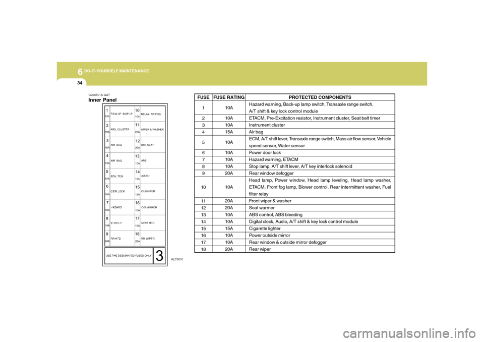
G200E01A-GATInner Panel
HLC5031
PROTECTED COMPONENTS
Hazard warning, Back-up lamp switch, Transaxle range switch,
A/T shift & key lock control module
ETACM, Pre-Excitation resistor, Instrument cluster, Seat belt timer
Instrument cluster
Air bag
ECM, A/T shift lever, Transaxle range switch, Mass air flow sensor, Vehicle
speed sensor, Water sensor
Power door lock
Hazard warning, ETACM
Stop lamp, A/T shift lever, A/T key interlock solenoid
Rear window defogger
Head lamp, Power window, Head lamp leveling, Head lamp washer,
ETACM, Front fog lamp, Blower control, Rear intermittent washer, Fuel
filter relay
Front wiper & washer
Seat warmer
ABS control, ABS bleeding
Digital clock, Audio, A/T shift & key lock control module
Cigarette lighter
Power outside mirror
Rear window & outside mirror defogger
Rear wiper
FUSE RATING
10A
10A
10A
15A
10A
10A
10A
10A
20A
10A
20A
20A
10A
10A
15A
10A
10A
20A FUSE
1
2
3
4
5
6
7
8
9
10
11
12
13
14
15
16
17
18
Page 190 of 219
EMISSION CONTROL SYSTEMS
7
Emission Control System ............................................. 7-2
Catalytic Converter ....................................................... 7-3
7
Page 191 of 219

7
EMISSION CONTROL SYSTEMS2
EMISSION CONTROL SYSTEM
Canister
Fuel vapors generated inside the fuel tank are
absorbed and stored in the onboard canister.
When the engine is running, the fuel vapors
absorbed in the canister are drawn into the
induction system through the purge control
solenoid valve.Purge Control Solenoid Valve (PCSV)The purge control solenoid valve is controlled
by the Engine Control Module (ECM); when
the engine coolant temperature is low during
idling, the PCSV closes so that evaporated fuel
is not taken into the engine. After the engine
warms-up during ordinary driving, the PCSV
opens to introduce evaporated fuel to the
engine.
H010B01A-AAT1. CRANKCASE EMISSION CONTROL
SYSTEMThe positive crankcase ventilation system is
employed to prevent air pollution caused by
blow-by gases being emitted from the crank-
case. This system supplies filtered fresh air to
the crankcase through the air intake hose.
Inside the crankcase, the fresh air mixes with
blow-by gases, then passes through the PCV
valve into the induction system.
H010A01A-AATYour Hyundai is equipped with an emission
control system to meet all requirements of the
U.S. Environmental Protection Agency or Cali-
fornia Air Resources Board.
There are three emission control systems
which are as follows.
1) Crankcase Emission Control System
2) Evaporative Emission Control System
3) Exhaust Emission Control System
In order to ensure the proper function of the
emission control systems, it is recommended
that you have your car inspected and main-
tained by an authorized Hyundai dealer in
accordance with the maintenance schedule in
this manual.
H010D01A-AAT3. EXHAUST EMISSION
CONTROL SYSTEMThe Exhaust Emission Control System is a
highly effective system which controls ex-
haust emissions while maintaining good ve-
hicle performace.
H010C01S-AAT2. Evaporative Emission Control (Includ-
ing ORVR: Onboard Refueling Vapor
Recovery) SystemThe Evaporative Emission Control System is
designed to prevent fuel vapors from escaping
into the atmosphere.
(The ORVR system is designed to allow the
vapors from the fuel tank to be loaded into a
canister while refueling at the gas station,
preventing the escape of fuel vapors into the
atmosphere.)
Page 192 of 219

7
EMISSION CONTROL SYSTEMS
3
CATALYTIC CONVERTER
!
!
H020A01A-AATAll Hyundai vehicles are equipped with a mono-
lith type three-way catalytic converter to
reduce the carbon monoxide, hydrocarbons
and nitrogen oxides contained in the exhaust
gas. Exhaust gases passing through the cata-
lytic converter cause it to operate at a very
high temperature. The introduction of large
amounts of unburned gasoline into the ex-
haust may cause the catalytic converter to
overheat and create a fire hazard. This risk
may be reduced by observing the following:system.
WARNING:
o Remember that your Hyundai dealer is
your best source of assistance.
o Do not stop your Hyundai over any
combustible material such as grass,
paper, leaves or rags. These materials
might contact the hot catalytic con-
verter and a fire might result.
HLC5022
Catalytic Converter
WARNING:
o Use unleaded fuel only.
o Maintain the engine in good operating
condition. Extremely high catalytic con-
verter temperatures can result from im-
proper operation of the electrical, igni-
tion or multiport electronic fuel injec-
tion.
o If your engine stalls, pings, knocks, or
is hard to start, have your Hyundai
dealer inspect and repair the problem
as soon as possible.
o Avoid driving with a very low fuel level.
Running out of gasoline may cause the
engine to misfire and result in damage
to the catalytic converter.
o Avoid idling the engine for periods
longer than 10 minutes.
o The vehicle should not be pushed or
pulled to get started. This may cause
the catalytic converter to overheat and
create a fire hazard.
o Do not touch the catalytic converter or
any other part of the exhaust system
while the catalytic converter is hot.
Shut off the engine, wait for at least one
hour before touching the catalytic con-
verter or any other part of the exhaust