Page 89 of 164

Network operator
When selected and confirmed, “Net-
work operator” icon allows manage-
ment of network Providers; the dis-
play shows the following icon keys fig.
86:
“Select”: to set operator selection
modes;
“Operator”: for manual operator
choice (which can only be manual or
preferential);
“OK”: to accept and store settings.
“Select”
When selecting and confirming this
key the user has three possible ways
to choose the network operator:– Automatic, fig. 87: the system will
automatically select the operator. In
the event that it is no longer able to
provide an adequate GMS field, it will
seek another administrator (if the ser-
vice is provided by the administrator
itself). In this case, the “Administrator”
graphic key will be OFF.
– Manual fig. 88: operator is chosen
manually. In this case “Operator” icon
key is enabled. If chosen operator is
no longer able to provide an adequate
GSM field, telephone functions will not
be available.
– Preferential: operator is chosen
manually. In this case “Operator” icon
key is enabled, and if chosen operator
is no longer able to provide an ade-
quate GSM field, the system automat-
ically looks for another available op-
erator.
“Operator”
Selecting and confirming “Operator”
key, displays the dialog box “User in-
formation – “Please wait…” until the
operators list is available. Available operators can be selected
in the list.
If network becomes not available,
“Network operator” key is disabled.
89
CONNECT NAV+
fig. 86
F0L3081g
fig. 88
F0L3083g
fig. 87
F0L3082g
Page 90 of 164

PIN
When selected and confirmed, the
“PIN” key enables to enter PIN man-
agement menu; after entering the PIN
code fig. 89, the display shows the fol-
lowing icon keysfig. 90:
“Change PIN”
This key enables to enter new PIN
code fig. 91; proceed as follows:
enter the old PIN code; the user is
asked to enter twice the new PIN
code (“New PIN 1” and “New PIN 2”
fields) and then to confirm. If the user
commits a mistake in retyping the PIN
code, the message “Please retype newPIN” is displayed. In this case restart
the entire procedure.
This key is active only if the PIN re-
quest is enabled.
“Enable PIN request”
This key enables/disables PIN check
on inserted SIM card. To change this
setting the system requires the new
PIN code.
This setting is saved in SIM card
memory.“Recall last PIN”
This key stores the first PIN entered,
sending it automatically to the SIM
card when required.
This key is active only if the PIN re-
quest is enabled.
This setting is saved in system
settings and not in SIM card
memory.
“OK”: to accept and store settings.
90
CONNECT NAV+
fig. 89
F0L3084g
fig. 90
F0L3085g
fig. 91
F0L3086g
Page 91 of 164

“Information” icon key
“Information” shows information re-
lated to the GSM service provider fig.
92. Press “ESC” to quit the “Informa-
tion” screen 14-fig. 1.“Settings” FUNCTION
Selecting “Settings” by turning and
pressing the knob 15-fig. 1, the dis-
play will showfig. 93screen and the
following icon keys:
“Ringer volume”: sets the volume
level of the telephone ringer;
“Redial”: in case of busy line, redials
automatically the called number (for a
preset number of times);
“Call forwarding”: enables or disables
call divert;
“Call forwarding no.”: allows input of
the phone number to which call is di-
verted. This key is enabled only if the
“Call forwarding” option is active.
“Enable call waiting”: enables or dis-
ables incoming call announcement dur-
ing a call.“OK”: to accept and store settings.
When the user modifies the call di-
vert settings, the display shows the di-
alog box “User information” – “Please
wait …”. A dedicated message will
warn the user if settings cannot be
changed.
91
CONNECT NAV+
fig. 92
F0L3087g
fig. 93
F0L3088g
Page 92 of 164

GENERAL
INFORMATION
The navigator integrated in the
CONNECT Nav+ allows you to
reach the chosen destination by visu-
al and voice instructions. Use of the
navigation system is quick, convenient,
safe and above all very flexible because
it allows you to call up already pro-
grammed destinations or points of ref-
erence such as hotels, monuments,
public structures, fuel stations.
The car position is determined
through the GPS system (Global Posi-
tioning System) installed on the car.
The GPS system is fitted with an an-
tenna and a reception module inte-
grated in the telematic system. This
system configuration dynamically
processes the satellite signals, those
from the right and left odometer, the
reversing signal and the information of
the gyroscope integrated in the navi-
gation computer, integrating them with
the current position of the car to ob-
tain an “estimated car point”.The navigation system helps the dri-
ver while he/she drives by suggesting
vocally and graphically the optimum
routing to reach the preset destina-
tion.
The navigation system suggestions do
not exempt the driver from full re-
sponsibility due to his/her driving be-
haviour and to compliance with road
and other traffic regulations. The re-
sponsibility for road safety always and
in any case lies with the car driver.IMPORTANT NOTES
– GPS reception is difficult under
trees, among tall buildings, in multi-lev-
el car parks, tunnels and everywhere
reception of the satellite antenna may
be hindered.
– The GPS system needs about 15
minutes for activation if the car bat-
tery is disconnected.
– The GPS system needs a few min-
utes to determine the new position of
the car if it is turned off and the car
is moved with the system off (e.g.: on
ferryboat).
– The GPS satellite aerial must not
be covered with metal or damp ob-
jects.
The instantaneous car position is
identified in the CD-ROM and shown
on the display together with the topo-
graphic characteristics of the area
memorised on the CD-ROM. Access
to data on the CD-ROM requires a
few moments waiting for the map dis-
plays.
92
CONNECT NAV+
N N
A A
V V
I I
G G
A A
T T
O O
R R
( (
N N
A A
V V
) )
Page 93 of 164

IMPORTANT NOTES
– Accurate self-adjustment of the
navigation system requires approx.
100 km of travel the first time and
when tyres are changed; during this
stage the calculated position could be
less accurate.
– Continuous lack of grip at the
wheels (for example skidding on ice),
makes the system temporarily detect
an incorrect position.
The navigation system is completely
managed by the telematic system,
therefore the only operations that
may be required are replacement of
the CD-ROM to set the map of an-
other area or an updated map.
Access to the navigation main func-
tions is gained by short push on “NAV”
key 18-fig. 1 , whereas a long push
(over 2 seconds) on the same key will
activate the NAV RPT function: navi-
gation voice instructions will be un-
available. To switch the function on
again press the “NAV” key 18-fig. 1for
over 2 seconds.When the system is switched on, the
display will, upon the first selection of
the navigating function, show the in-
structions for using the system. The
text will be as follows:
“The FIAT navigation system guides
you in traffic and helps you reach your
destination. Comply with all local traf-
fic regulations, which take precedence
over the manoeuvres indicated by the
navigation system. Full responsibility
for operating the vehicle and observ-
ing all traffic regulations lies with the
driver”.
This page will not be displayed as
long as the ignition key is to ON.SCREEN OPTIONS
AND FUNCTIONS
The main information and functions
provided and managed by the naviga-
tion system are:
– GPS signal symbol which differs in
colour depending on the quality of re-
ception ;
– voice and visual instructions with
indications of distance from the des-
tination and planned arrival time;
– detailed map in different colours
and with different scales to clearly
show the car position, route and des-
tination;
– customisation of the navigation sys-
tem with possibility of entering pre-
memorised destinations;
– automatic memorising of the last
10 destinations;
– name of current street;
93
CONNECT NAV+
Page 94 of 164

– possibility to choose the route ac-
cording to personal preference;
– information on current position;
– information on arrival time.
If the system contains a wrong CD-
ROM, an audio CD or no CD, when-
ever the system asks for the navigation
CD-ROM for route calculation or map
up-date, the insertion prompt will ap-
pear on the display.
Should a CD be inserted in the
wrong side, the display will show the
message “CD ERROR”. In this event,
eject the CD and re-insert it proper-
ly.GRAPHIC INSTRUCTIONS
The operations to be performed will
be displayed by means of arrows or
pictograms on the main page of the
navigating function.
The downward graphic symbol rep-
resents next manoeuvre (turn left,
right, straight on, U-turn) while the up-
ward graphic symbol represents the
next one. The number displayed un-
der the graphic symbol indicates the
car distance from the manoeuvre
point. VOICE INSTRUCTIONS
The voice instructions provided by
the system guide you to your destina-
tion and suggest all manoeuvres to be
carried out in due time: in particular,
the manoeuvres is announced first and
then detailed instructions are given.
Press briefly the “NAV” key 18-fig.
1to repeat the last voice instruction.
To adjust the volume turn the knob
17-fig. 1during voice instruction.
If necessary, press again “NAV ” 18-
fig. 1to repeat the voice instruction
and adjust the volume.
94
CONNECT NAV+
Page 95 of 164

The navigator CD-ROM player 7-fig.
1is located on the CONNECT Nav+
front panel and it is the same used for
the audio CD. Therefore, it is not pos-
sible to use the player for audio and
navigation CD-ROM at the same time:
however, the navigation system can
operate partially even without insert-
ing the navigation CD-ROM.
In this case, when pressing key
˚8-
fig.1to remove the CD-ROM with
navigation function engaged (to then
insert an audio CD), the following two
cases may occur:
1) If no route has been calculated,
when ejecting the CD ROM only the
information on the car position (co-
ordinates) fig. 94will be available.2) The route previously calculated is
still valid, the system provides the user
with any instruction to reach the des-
tination.
If the route previously calculated is
still valid, the system will show the
screen in fig. 95.
If the user selects and confirms
“YES”, the system will store the navi-
gation data required to reach the set
destination; this operation requires a
few seconds and the display will
prompt the message to wait fig. 96.After loading, the CD-ROM is eject-
ed and the system restarts its naviga-
tion function with the maximum scale
of “2 km”; therefore it may be possi-
ble that not all of the route is visible.
If the user selects and confirms
“NO”, route guide will be deactivated
and the display will go back to screen
in fig. 94.
Moreover, navigation in these con-
ditions involves limitations and there-
fore some functions and commands
will not be available. Also information
shown on the map will be limited.
95
CONNECT NAV+
NAVIGATION CD-ROM PLAYER
fig. 94
F0L3125g
fig. 95
F0L3126g
fig. 96
F0L3127g
Page 96 of 164
.
– Car position on the map (ico")
MAIN SCREEN
Main navigator screen fig. 98shows
the following information:
– Time.
– GPS and GSM signal strengths.
– Date.
– Audio info.
– Active mode (NAV).
– Car position on the map (icon).
– Map scale.At the bottom of the screen are dis-
played the following options, that can
be activated by the corresponding
multifunction keys 16-fig. 1:
H1and H2(Home 1 and Home 2):
start route calculation towards one of
the two predefine or frequently used
destinations. If no point has been de-
fined as “Home 1” or “Home 2”, a
warning reminds the user that the
function is not available.
Info: displays info on car position and
destination. When the navigation system is no
longer able to continue destination
guidance or the car is now out of the
loaded map section, the system
prompts for inserting the navigation
CD-ROM fig. 97. If the user does not
insert the CD-ROM, the system re-
turns to the status shown in fig. 94.
IMPORTANT
The driver is always responsible
for compliance with the enforced
traffic regulations: any indication
based on wrong map data leading
to unauthorised driving manoeu-
vres MUST NOT be followed.
96
CONNECT NAV+
fig. 97
F0L3128g
fig. 98
F0L3129g
fig. 99
F0L3130g
 1
1 2
2 3
3 4
4 5
5 6
6 7
7 8
8 9
9 10
10 11
11 12
12 13
13 14
14 15
15 16
16 17
17 18
18 19
19 20
20 21
21 22
22 23
23 24
24 25
25 26
26 27
27 28
28 29
29 30
30 31
31 32
32 33
33 34
34 35
35 36
36 37
37 38
38 39
39 40
40 41
41 42
42 43
43 44
44 45
45 46
46 47
47 48
48 49
49 50
50 51
51 52
52 53
53 54
54 55
55 56
56 57
57 58
58 59
59 60
60 61
61 62
62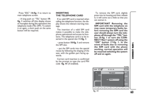 63
63 64
64 65
65 66
66 67
67 68
68 69
69 70
70 71
71 72
72 73
73 74
74 75
75 76
76 77
77 78
78 79
79 80
80 81
81 82
82 83
83 84
84 85
85 86
86 87
87 88
88 89
89 90
90 91
91 92
92 93
93 94
94 95
95 96
96 97
97 98
98 99
99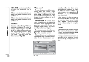 100
100 101
101 102
102 103
103 104
104 105
105 106
106 107
107 108
108 109
109 110
110 111
111 112
112 113
113 114
114 115
115 116
116 117
117 118
118 119
119 120
120 121
121 122
122 123
123 124
124 125
125 126
126 127
127 128
128 129
129 130
130 131
131 132
132 133
133 134
134 135
135 136
136 137
137 138
138 139
139 140
140 141
141 142
142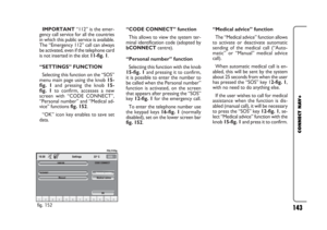 143
143 144
144 145
145 146
146 147
147 148
148 149
149 150
150 151
151 152
152 153
153 154
154 155
155 156
156 157
157 158
158 159
159 160
160 161
161 162
162 163
163