2005 CHRYSLER VOYAGER Module
[x] Cancel search: ModulePage 1175 of 2339
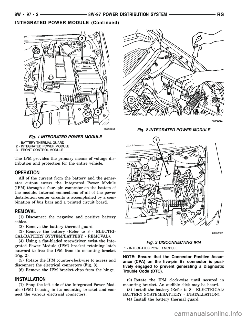
The IPM provides the primary means of voltage dis-
tribution and protection for the entire vehicle.
OPERATION
All of the current from the battery and the gener-
ator output enters the Integrated Power Module
(IPM) through a four- pin connector on the bottom of
the module. Internal connections of all of the power
distribution center circuits is accomplished by a com-
bination of bus bars and a printed circuit board.
REMOVAL
(1) Disconnect the negative and positive battery
cables.
(2) Remove the battery thermal guard.
(3) Remove the battery (Refer to 8 - ELECTRI-
CAL/BATTERY SYSTEM/BATTERY - REMOVAL).
(4) Using a flat-bladed screwdriver, twist the Inte-
grated Power Module (IPM) bracket retaining latch
outward to free the IPM from its mounting bracket
(Fig. 2).
(5) Rotate the IPM counter-clockwise to access and
disconnect the electrical connectors (Fig. 3).
(6) Remove the IPM bracket clips from the hinge.
INSTALLATION
(1) Snap the left side of the Integrated Power Mod-
ule (IPM) housing in its mounting bracket and con-
nect the various electrical connectors.NOTE: Ensure that the Connector Positive Assur-
ance (CPA) on the five-pin B+ connector is posi-
tively engaged to prevent generating a Diagnostic
Trouble Code (DTC).
(2) Rotate the IPM clock-wise until secured in
mounting bracket. An audible click may be heard.
(3) Install the battery (Refer to 8 - ELECTRICAL/
BATTERY SYSTEM/BATTERY - INSTALLATION).
(4) Install the battery thermal guard.
Fig. 1 INTEGRATED POWER MODULE
1 - BATTERY THERMAL GUARD
2 - INTEGRATED POWER MODULE
3 - FRONT CONTROL MODULE
Fig. 2 INTEGRATED POWER MODULE
Fig. 3 DISCONNECTING IPM
1 - INTEGRATED POWER MODULE
8W - 97 - 2 8W-97 POWER DISTRIBUTION SYSTEMRS
INTEGRATED POWER MODULE (Continued)
Page 1176 of 2339
(5) Connect the negative and positive battery
cables.
(6) Using a scan tool, check for any stored diagnos-
tic trouble codes. Ensure that all vehicle options are
operational.
IOD FUSE
DESCRIPTION
All vehicles are equipped with an Ignition-Off
Draw (IOD) fuse that is removed from its normal
cavity in the Integrated Power Module (IPM) when
the vehicle is shipped from the factory. Dealer per-
sonnel are to remove the IOD fuse from the storage
location and install it into the IPM fuse cavity
marked IOD as part of the preparation procedures
performed just prior to new vehicle delivery.
The IOD fuse is a 20 ampere blade-type mini fuse
and, when removed, it is stored in a fuse cavity adja-
cent to the washer fuse within the IPM.
OPERATION
The term ignition-off draw (IOD) identifies a nor-
mal condition where power is being drained from the
battery with the ignition switch in the Off position.
The IOD fuse feeds the memory and sleep mode func-
tions for some of the electronic modules in the vehicle
as well as various other accessories that require bat-
tery current when the ignition switch is in the Off
position, including the clock. The only reason the
IOD fuse is removed is to reduce the normal IOD of
the vehicle electrical system during new vehicle
transportation and pre-delivery storage to reduce
battery depletion, while still allowing vehicle opera-
tion so that the vehicle can be loaded, unloaded and
moved as needed by both vehicle transportation com-
pany and dealer personnel.
The IOD fuse is removed from the Integrated
Power Module (IPM) fuse cavity when the vehicle is
shipped from the assembly plant. Dealer personnel
must install the IOD fuse when the vehicle is being
prepared for delivery in order to restore full electrical
system operation. Once the vehicle is prepared for
delivery, the IOD function of this fuse becomes trans-
parent and the fuse that has been assigned the IOD
designation becomes only another Fused B(+) circuit
fuse. The IOD fuse serves no useful purpose to the
dealer technician in the service or diagnosis of any
vehicle system or condition, other than the same pur-
pose as that of any other standard circuit protection
device.
The IOD fuse can be used by the vehicle owner as
a convenient means of reducing battery depletion
when a vehicle is to be stored for periods not to
exceed approximately thirty days. However, it mustbe remembered that removing the IOD fuse will not
eliminate IOD, but only reduce this normal condition.
If a vehicle will be stored for more than thirty days,
the battery negative cable should be disconnected to
eliminate normal IOD; and, the battery should be
tested and recharged at regular intervals during the
vehicle storage period to prevent the battery from
becoming discharged or damaged.
POWER OUTLET
DESCRIPTION
Two power outlets are installed in the instrument
panel center lower bezel. Two additional power out-
lets are incorporated into the left rear C-pillar and
the center console (if equipped). The power outlets
bases are secured by a snap fit. A hinged plug flips
closed to conceal and protect the power outlet base
when not in use.
OPERATION
The power outlet base or receptacle shell is con-
nected to ground, and an insulated contact in the
bottom of the shell is connected to battery current.
The power outlet on the instrument panel marked
with a battery receives battery voltage from a fuse in
the Integrated Power Module (IPM) at all times. The
other power outlet on the instrument panel marked
with a key receives battery voltage only when the
key is in the on position.
The power outlet located in the center console
receives battery voltage all the time when positioned
between thefront seatsand key-on voltage when
positioned between therear seats. The power outlet
located on the C-pillar receives battery voltage only
when the key is in the ON position.
DIAGNOSIS AND TESTING
DIAGNOSIS & TESTING - POWER OUTLET
WARNING: ON VEHICLES EQUIPPED WITH AIR-
BAGS, REFER TO RESTRAINTS BEFORE ATTEMPT-
ING ANY STEERING WHEEL, STEERING COLUMN,
SEAT OR INSTRUMENT PANEL COMPONENT DIAG-
NOSIS OR SERVICE. FAILURE TO TAKE THE
PROPER PRECAUTIONS COULD RESULT IN ACCI-
DENTAL AIRBAG DEPLOYMENT AND POSSIBLE
PERSONAL INJURY.
(1) Check the fused B(+) fuse in the Integrated
Power Module (IPM). If OK, go to Step 2. If not OK,
repair the shorted circuit or component as required
and replace the faulty fuse.
RS8W-97 POWER DISTRIBUTION SYSTEM8W-97-3
INTEGRATED POWER MODULE (Continued)
Page 1201 of 2339
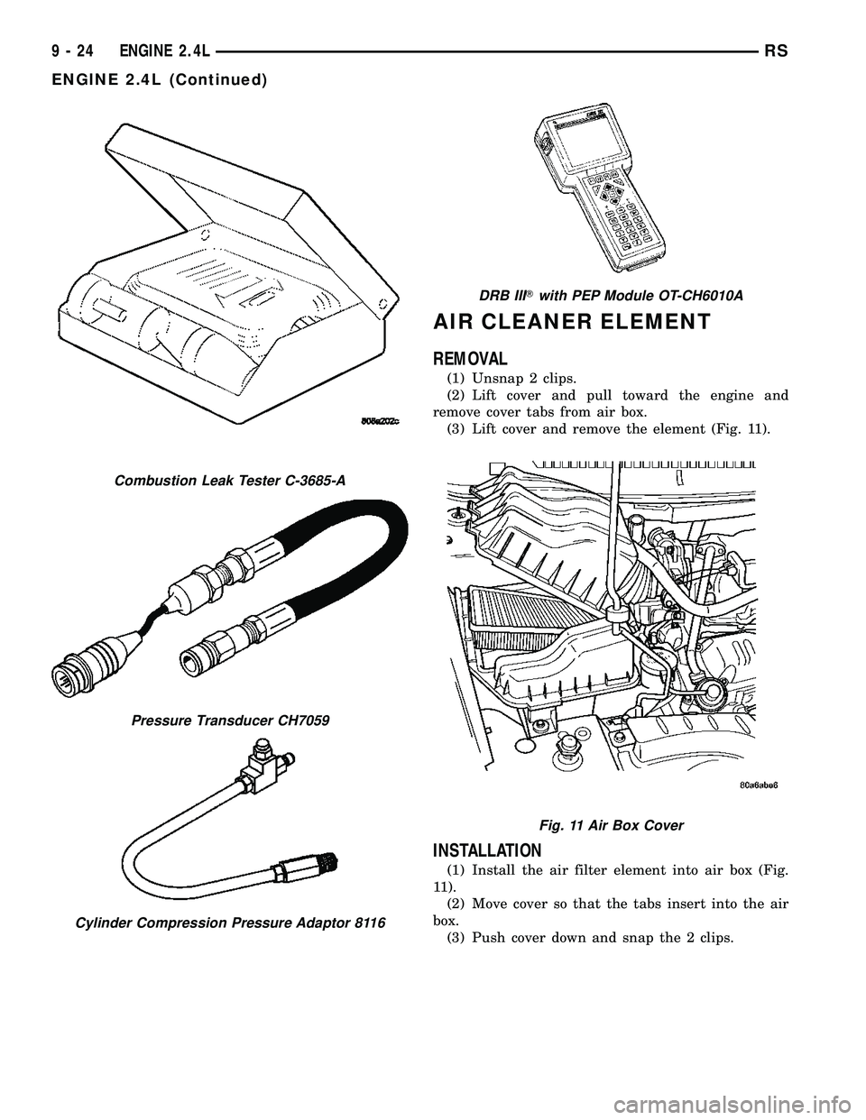
AIR CLEANER ELEMENT
REMOVAL
(1) Unsnap 2 clips.
(2) Lift cover and pull toward the engine and
remove cover tabs from air box.
(3) Lift cover and remove the element (Fig. 11).
INSTALLATION
(1) Install the air filter element into air box (Fig.
11).
(2) Move cover so that the tabs insert into the air
box.
(3) Push cover down and snap the 2 clips.
Combustion Leak Tester C-3685-A
Pressure Transducer CH7059
Cylinder Compression Pressure Adaptor 8116
DRB IIITwith PEP Module OT-CH6010A
Fig. 11 Air Box Cover
9 - 24 ENGINE 2.4LRS
ENGINE 2.4L (Continued)
Page 1265 of 2339
(3) Place a shop towel around the spark plugs
when removing them from the engine. This will catch
any fluid that may possibly be in the cylinder under
pressure.
(4) With all spark plugs removed, rotate engine
crankshaft using a breaker bar and socket.
(5) Identify the fluid in the cylinder(s) (i.e., cool-
ant, fuel, oil or other).
(6) Make sure all fluid has been removed from the
cylinders. Inspect engine for damage (i.e., connecting
rods, pistons, valves, etc.)
(7) Repair engine or components as necessary to
prevent this problem from re-occurring.
CAUTION: Squirt approximately one teaspoon of oil
into the cylinders, rotate engine to lubricate the cyl-
inder walls to prevent damage on restart.
(8) Install new spark plugs.
(9) Drain engine oil and remove oil filter.
(10) Install a new oil filter.
(11) Fill engine with specified amount of approved
oil.
(12) Connect negative battery cable.
(13) Start engine and check for any leaks.
STANDARD PROCEDURE - REPAIR OF
DAMAGED OR WORN THREADS
Damaged or worn threads (excluding spark plug
and camshaft bearing cap attaching threads) can be
repaired. Essentially, this repair consists of drilling
out worn or damaged threads, tapping the hole with
a special Heli-Coil Tap, (or equivalent) and installing
an insert into the tapped hole. This brings the hole
back to its original thread size.
CAUTION: Be sure that the tapped holes maintain
the original center line.
Heli-Coil tools and inserts are readily available
from automotive parts jobbers.
STANDARD PROCEDURE - ENGINE CORE AND
OIL GALLERY PLUGS
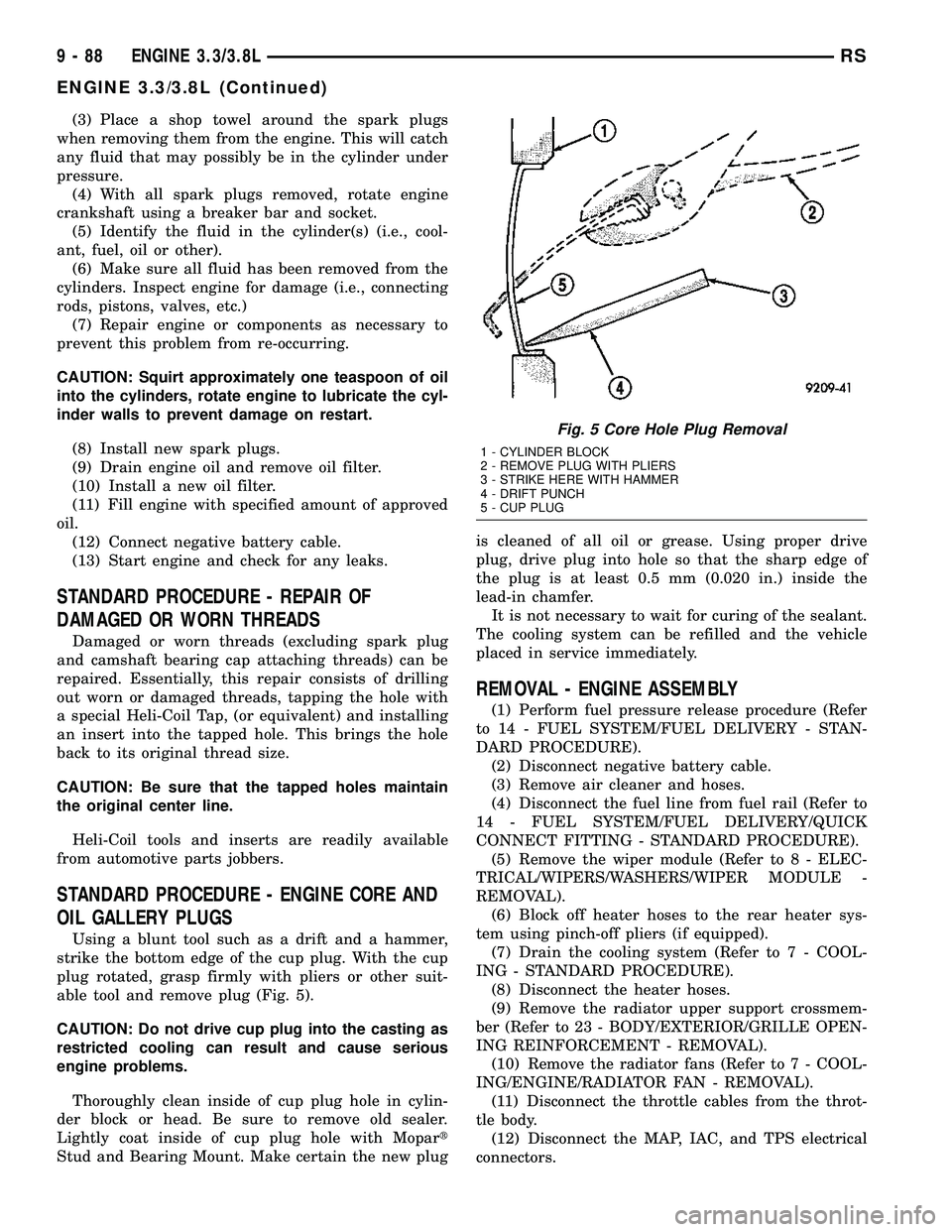
Using a blunt tool such as a drift and a hammer,
strike the bottom edge of the cup plug. With the cup
plug rotated, grasp firmly with pliers or other suit-
able tool and remove plug (Fig. 5).
CAUTION: Do not drive cup plug into the casting as
restricted cooling can result and cause serious
engine problems.
Thoroughly clean inside of cup plug hole in cylin-
der block or head. Be sure to remove old sealer.
Lightly coat inside of cup plug hole with Mopart
Stud and Bearing Mount. Make certain the new plugis cleaned of all oil or grease. Using proper drive
plug, drive plug into hole so that the sharp edge of
the plug is at least 0.5 mm (0.020 in.) inside the
lead-in chamfer.
It is not necessary to wait for curing of the sealant.
The cooling system can be refilled and the vehicle
placed in service immediately.
REMOVAL - ENGINE ASSEMBLY
(1) Perform fuel pressure release procedure (Refer
to 14 - FUEL SYSTEM/FUEL DELIVERY - STAN-
DARD PROCEDURE).
(2) Disconnect negative battery cable.
(3) Remove air cleaner and hoses.
(4) Disconnect the fuel line from fuel rail (Refer to
14 - FUEL SYSTEM/FUEL DELIVERY/QUICK
CONNECT FITTING - STANDARD PROCEDURE).
(5) Remove the wiper module (Refer to 8 - ELEC-
TRICAL/WIPERS/WASHERS/WIPER MODULE -
REMOVAL).
(6) Block off heater hoses to the rear heater sys-
tem using pinch-off pliers (if equipped).
(7) Drain the cooling system (Refer to 7 - COOL-
ING - STANDARD PROCEDURE).
(8) Disconnect the heater hoses.
(9) Remove the radiator upper support crossmem-
ber (Refer to 23 - BODY/EXTERIOR/GRILLE OPEN-
ING REINFORCEMENT - REMOVAL).
(10) Remove the radiator fans (Refer to 7 - COOL-
ING/ENGINE/RADIATOR FAN - REMOVAL).
(11) Disconnect the throttle cables from the throt-
tle body.
(12) Disconnect the MAP, IAC, and TPS electrical
connectors.
Fig. 5 Core Hole Plug Removal
1 - CYLINDER BLOCK
2 - REMOVE PLUG WITH PLIERS
3 - STRIKE HERE WITH HAMMER
4 - DRIFT PUNCH
5 - CUP PLUG
9 - 88 ENGINE 3.3/3.8LRS
ENGINE 3.3/3.8L (Continued)
Page 1270 of 2339
(49) Install the radiator upper support crossmem-
ber (Refer to 23 - BODY/EXTERIOR/GRILLE OPEN-
ING REINFORCEMENT - INSTALLATION).
(50) Install the wiper module (Refer to 8 - ELEC-
TRICAL/WIPERS/WASHERS/WIPER MODULE -
INSTALLATION).
(51) Connect the fuel line to fuel rail (Refer to 14 -
FUEL SYSTEM/FUEL DELIVERY/FUEL LINES -
STANDARD PROCEDURE).
(52) Install the air cleaner and hoses.
(53) Install new oil filter. Fill engine crankcase
with proper oil to correct level.
(54) Connect negative cable to battery.
(55) Fill the cooling system (Refer to 7 - COOLING
- STANDARD PROCEDURE).
(56) Start engine and run until operating temper-
ature is reached.
(57) Adjust transmission linkage, if necessary.
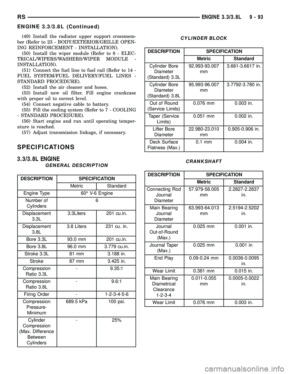
SPECIFICATIONS
3.3/3.8L ENGINE
GENERAL DESCRIPTION
DESCRIPTION SPECIFICATION
Metric Standard
Engine Type 60É V-6 Engine
Number of
Cylinders6
Displacement
3.3L3.3Liters 201 cu.in.
Displacement
3.8L3.8 Liters 231 cu. in.
Bore 3.3L 93.0 mm 201 cu.in.
Bore 3.8L 96.0 mm 3.779 cu.in.
Stroke 3.3L 81 mm 3.188 in.
Stroke 87 mm 3.425 in.
Compression
Ratio 3.3L- 9.35:1
Compression
Ratio 3.8L- 9.6:1
Firing Order - 1-2-3-4-5-6
Compression
Pressure-
Minimum689.5 kPa 100 psi.
Cylinder
Compression
(Max. Difference
Between
Cylinders- 25%
CYLINDER BLOCK
DESCRIPTION SPECIFICATION
Metric Standard
Cylinder Bore
Diameter
(Standard) 3.3L92.993-93.007
mm3.661-3.6617 in.
Cylinder Bore
Diameter
(Standard) 3.8L95.993-96.007
mm3.7792-3.780 in.
Out of Round
(Service Limits)0.076 mm 0.003 in.
Taper (Service
Limits)0.051 mm 0.002 in.
Lifter Bore
Diameter22.980-23.010
mm0.905-0.906 in.
Deck Surface
Flatness (Max.)0.1 mm 0.004 in.
CRANKSHAFT
DESCRIPTION SPECIFICATION
Metric Standard
Connecting Rod
Journal
Diameter57.979-58.005
mm2.2827-2.2837
in.
Main Bearing
Journal
Diameter63.993-64.013
mm2.5194-2.5202
in.
Journal
Out-of-Round
(Max.)0.025 mm 0.001 in.
Journal Taper
(Max.)0.025 mm 0.001 in
End Play 0.09-0.24 mm 0.0036-0.0095
in.
Wear Limit 0.381 mm 0.015 in.
Main Bearing
Diametrical
Clearance
1-2-3-40.011-0.055
mm0.0005-0.0022
in.
Wear Limit 0.076 mm 0.003 in.
RSENGINE 3.3/3.8L9-93
ENGINE 3.3/3.8L (Continued)
Page 1278 of 2339
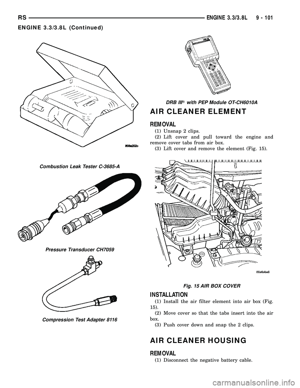
AIR CLEANER ELEMENT
REMOVAL
(1) Unsnap 2 clips.
(2) Lift cover and pull toward the engine and
remove cover tabs from air box.
(3) Lift cover and remove the element (Fig. 15).
INSTALLATION
(1) Install the air filter element into air box (Fig.
15).
(2) Move cover so that the tabs insert into the air
box.
(3) Push cover down and snap the 2 clips.
AIR CLEANER HOUSING
REMOVAL
(1) Disconnect the negative battery cable.
Combustion Leak Tester C-3685-A
Pressure Transducer CH7059
Compression Test Adapter 8116
DRB IIITwith PEP Module OT-CH6010A
Fig. 15 AIR BOX COVER
RSENGINE 3.3/3.8L9 - 101
ENGINE 3.3/3.8L (Continued)
Page 1283 of 2339
CYLINDER HEAD COVER -
RIGHT
REMOVAL
(1) Disconnect negative cable from battery.
(2) Remove the wiper module. (Refer to 8 - ELEC-
TRICAL/WIPERS/WASHERS/WIPER MODULE -
REMOVAL)
(3) Disconnect spark plug wires from plugs.
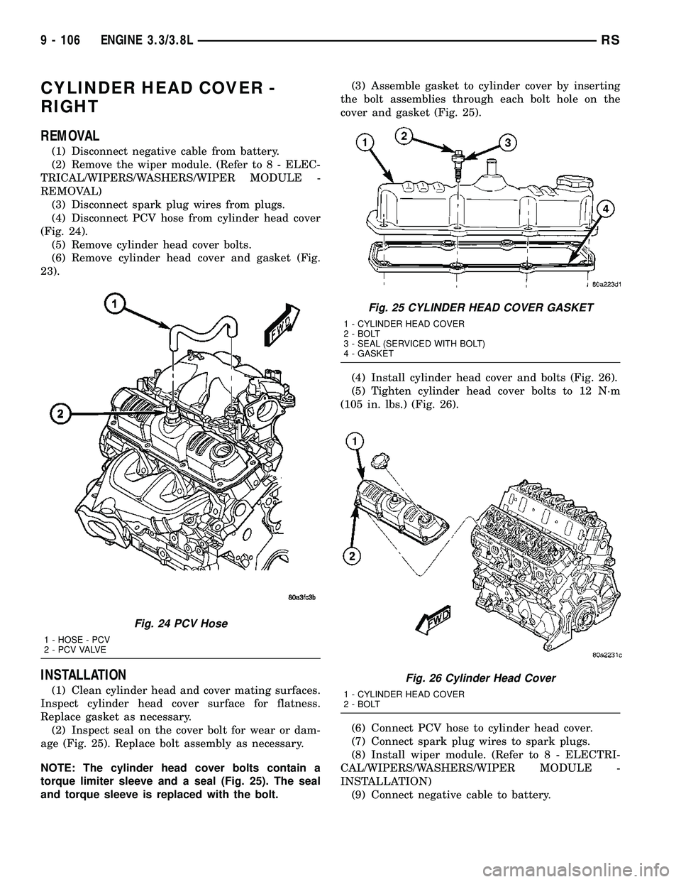
(4) Disconnect PCV hose from cylinder head cover
(Fig. 24).
(5) Remove cylinder head cover bolts.
(6) Remove cylinder head cover and gasket (Fig.
23).
INSTALLATION
(1) Clean cylinder head and cover mating surfaces.
Inspect cylinder head cover surface for flatness.
Replace gasket as necessary.
(2) Inspect seal on the cover bolt for wear or dam-
age (Fig. 25). Replace bolt assembly as necessary.
NOTE: The cylinder head cover bolts contain a
torque limiter sleeve and a seal (Fig. 25). The seal
and torque sleeve is replaced with the bolt.(3) Assemble gasket to cylinder cover by inserting
the bolt assemblies through each bolt hole on the
cover and gasket (Fig. 25).
(4) Install cylinder head cover and bolts (Fig. 26).
(5) Tighten cylinder head cover bolts to 12 N´m
(105 in. lbs.) (Fig. 26).
(6) Connect PCV hose to cylinder head cover.
(7) Connect spark plug wires to spark plugs.
(8) Install wiper module. (Refer to 8 - ELECTRI-
CAL/WIPERS/WASHERS/WIPER MODULE -
INSTALLATION)
(9) Connect negative cable to battery.
Fig. 24 PCV Hose
1 - HOSE - PCV
2 - P C V VA LV E
Fig. 25 CYLINDER HEAD COVER GASKET
1 - CYLINDER HEAD COVER
2 - BOLT
3 - SEAL (SERVICED WITH BOLT)
4 - GASKET
Fig. 26 Cylinder Head Cover
1 - CYLINDER HEAD COVER
2 - BOLT
9 - 106 ENGINE 3.3/3.8LRS
Page 1329 of 2339

(9) Install the upper intake manifold. (Refer to 9 -
ENGINE/MANIFOLDS/INTAKE MANIFOLD -
INSTALLATION)
(10) Connect negative battery cable.(11) Fill the cooling system. (Refer to 7 - COOL-
ING - STANDARD PROCEDURE)
EXHAUST MANIFOLD - RIGHT
REMOVAL
(1) Disconnect battery negative cable.
(2) Remove the wiper module. (Refer to 8 - ELEC-
TRICAL/WIPERS/WASHERS/WIPER MODULE -
REMOVAL)
(3) Disconnect spark plug wires.
(4) Remove bolts fastening crossover pipe to
exhaust manifold (Fig. 125).
(5) Disconnect and remove the upstream oxygen
sensor (Fig. 128).
Fig. 122 INTAKE MANIFOLD - LOWER
1 - INTAKE MANIFOLD - LOWER
2 - BOLT - GASKET END SEAL RETAINER
3 - GASKET
4 - BOLT - LOWER INTAKE MANIFOLD
Fig. 123 Intake Manifold Gasket Sealing
1 - SEALER LOCATIONS
Fig. 124 LOWER MANIFOLD TIGHTENING
SEQUENCE
Fig. 125 CROSS-OVER PIPE
1 - CROSS-OVER PIPE
2 - BOLT
3 - GASKET
4 - FLAG NUT
9 - 152 ENGINE 3.3/3.8LRS
INTAKE MANIFOLD - LOWER (Continued)