2005 CHRYSLER VOYAGER Module
[x] Cancel search: ModulePage 1125 of 2339

CONNECTOR NAME/NUMBER COLOR LOCATION FIG.
Right Sliding Door Motor BK At Sliding Door 45
Right Speed Control Switch WT At Steering Wheel N/S
Right Turn Signal Lamp (Export) OR At Lamp N/S
Right Visor/Vanity Lamp BK At Lamp N/S
Sentry Key Remote Entry Module
(SKREEM)BK At Steering Column 20, 21, 22, 23, 31
Siren (United Kingdom) BK Left Front Body N/S
Speed Control Servo (Gas) BK Near Controller Antilock Brake 11, 17, 18
Sunroof Module (Except Export) BK At Sunroof N/S
Sunroof Switch (Except Export) NAT Near Overhead Console N/S
Thatcham Alarm Module (United
Kingdom)BK Top Right Side of Instrument Panel
Near SpeakerN/S
Throttle Position Sensor (Gas) GY On Throttle Body 10, 11, 17
Traction Control Switch BK Rear of Swtich 21, 22, 31
Trailer Tow Connector (Except
Export)Left Quarter Panel N/S
Transmission Control Relay
(Diesel)Near Transmission 16
Transmission Range Sensor DKGY Top of Transmission 14, 19
Transmission Solenoid/Pressure
Switch AssemblyBK Side of Transmission 14, 19
Vehicle Speed Sensor (MTX) BK Rear of Transmission 16
Washer Fluid Level Switch BK Bottom of Reservoir 3
Washer Pump Motor BK Right Fender Well 3
Water in Fuel Sensor (Diesel) BK Left Rear Engine Compartment N/S
Wiper Module DKGY Left Side Cowl 6
GROUNDS
GROUND NUMBER LOCATION FIG.
G100 Body Ground Near Powertrain Control Module N/S
G101 Above Starter 13, 15, 18
G102 Left Headlamp Area 1
G103 Above Starter 15
G200 Left Side of Instrument Panel 20, 21 29
G201 Right Side of Instrument Panel 20, 24, 29
G202 Near Radio N/S
G300 Left B Pillar 32
G301 Right B Pillar 33, 39
G302 Left Rear Quarter 47
G303 Liftgate Ground 49
8W - 91 - 12 8W-91 CONNECTOR/GROUND/SPLICE LOCATIONRS
CONNECTOR/GROUND/SPLICE LOCATION (Continued)
Page 1126 of 2339
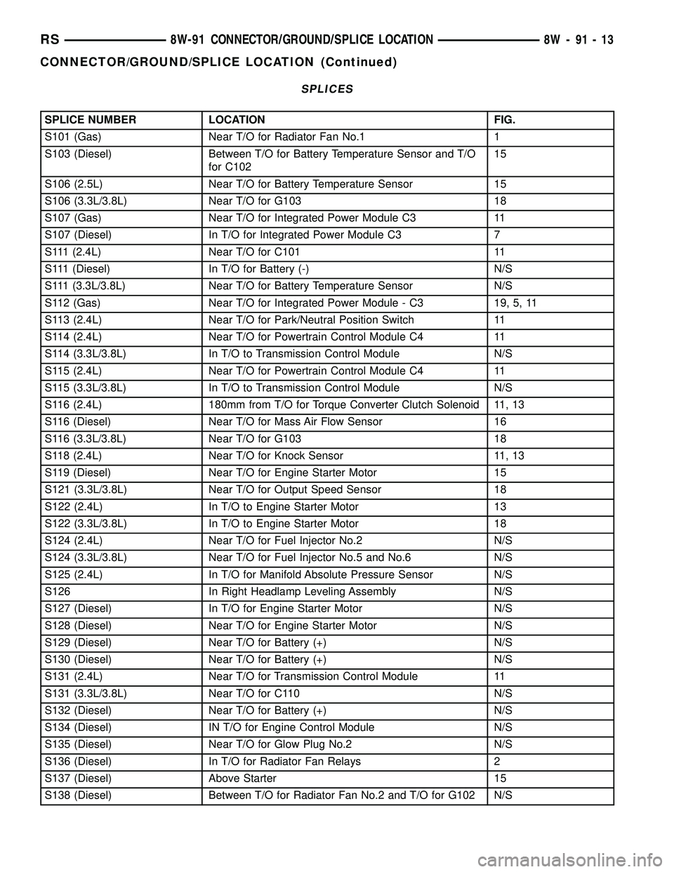
SPLICES
SPLICE NUMBER LOCATION FIG.
S101 (Gas) Near T/O for Radiator Fan No.1 1
S103 (Diesel) Between T/O for Battery Temperature Sensor and T/O
for C10215
S106 (2.5L) Near T/O for Battery Temperature Sensor 15
S106 (3.3L/3.8L) Near T/O for G103 18
S107 (Gas) Near T/O for Integrated Power Module C3 11
S107 (Diesel) In T/O for Integrated Power Module C3 7
S111 (2.4L) Near T/O for C101 11
S111 (Diesel) In T/O for Battery (-) N/S
S111 (3.3L/3.8L) Near T/O for Battery Temperature Sensor N/S
S112 (Gas) Near T/O for Integrated Power Module - C3 19, 5, 11
S113 (2.4L) Near T/O for Park/Neutral Position Switch 11
S114 (2.4L) Near T/O for Powertrain Control Module C4 11
S114 (3.3L/3.8L) In T/O to Transmission Control Module N/S
S115 (2.4L) Near T/O for Powertrain Control Module C4 11
S115 (3.3L/3.8L) In T/O to Transmission Control Module N/S
S116 (2.4L) 180mm from T/O for Torque Converter Clutch Solenoid 11, 13
S116 (Diesel) Near T/O for Mass Air Flow Sensor 16
S116 (3.3L/3.8L) Near T/O for G103 18
S118 (2.4L) Near T/O for Knock Sensor 11, 13
S119 (Diesel) Near T/O for Engine Starter Motor 15
S121 (3.3L/3.8L) Near T/O for Output Speed Sensor 18
S122 (2.4L) In T/O to Engine Starter Motor 13
S122 (3.3L/3.8L) In T/O to Engine Starter Motor 18
S124 (2.4L) Near T/O for Fuel Injector No.2 N/S
S124 (3.3L/3.8L) Near T/O for Fuel Injector No.5 and No.6 N/S
S125 (2.4L) In T/O for Manifold Absolute Pressure Sensor N/S
S126 In Right Headlamp Leveling Assembly N/S
S127 (Diesel) In T/O for Engine Starter Motor N/S
S128 (Diesel) Near T/O for Engine Starter Motor N/S
S129 (Diesel) Near T/O for Battery (+) N/S
S130 (Diesel) Near T/O for Battery (+) N/S
S131 (2.4L) Near T/O for Transmission Control Module 11
S131 (3.3L/3.8L) Near T/O for C110 N/S
S132 (Diesel) Near T/O for Battery (+) N/S
S134 (Diesel) IN T/O for Engine Control Module N/S
S135 (Diesel) Near T/O for Glow Plug No.2 N/S
S136 (Diesel) In T/O for Radiator Fan Relays 2
S137 (Diesel) Above Starter 15
S138 (Diesel) Between T/O for Radiator Fan No.2 and T/O for G102 N/S
RS8W-91 CONNECTOR/GROUND/SPLICE LOCATION8W-91-13
CONNECTOR/GROUND/SPLICE LOCATION (Continued)
Page 1127 of 2339
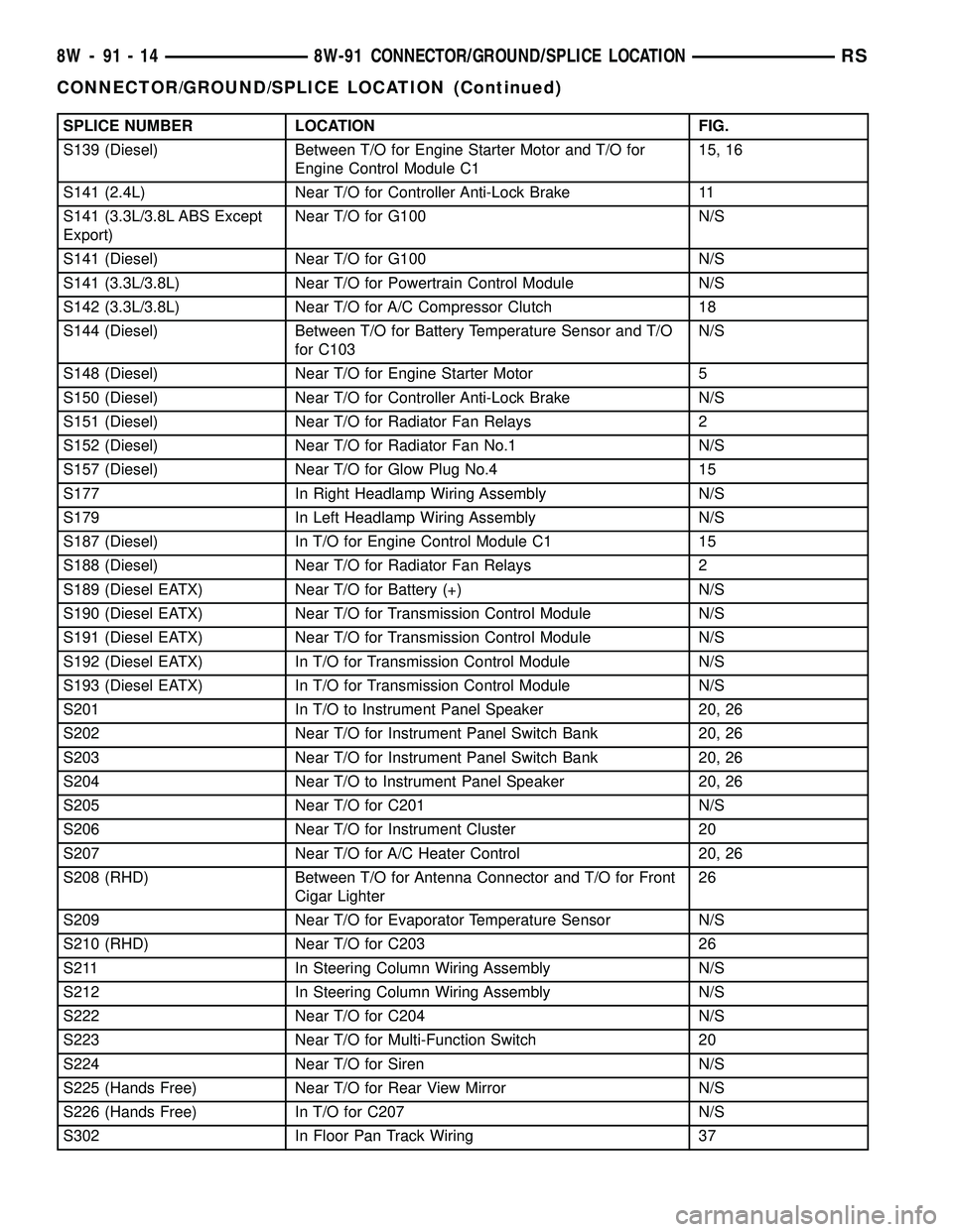
SPLICE NUMBER LOCATION FIG.
S139 (Diesel) Between T/O for Engine Starter Motor and T/O for
Engine Control Module C115, 16
S141 (2.4L) Near T/O for Controller Anti-Lock Brake 11
S141 (3.3L/3.8L ABS Except
Export)Near T/O for G100 N/S
S141 (Diesel) Near T/O for G100 N/S
S141 (3.3L/3.8L) Near T/O for Powertrain Control Module N/S
S142 (3.3L/3.8L) Near T/O for A/C Compressor Clutch 18
S144 (Diesel) Between T/O for Battery Temperature Sensor and T/O
for C103N/S
S148 (Diesel) Near T/O for Engine Starter Motor 5
S150 (Diesel) Near T/O for Controller Anti-Lock Brake N/S
S151 (Diesel) Near T/O for Radiator Fan Relays 2
S152 (Diesel) Near T/O for Radiator Fan No.1 N/S
S157 (Diesel) Near T/O for Glow Plug No.4 15
S177 In Right Headlamp Wiring Assembly N/S
S179 In Left Headlamp Wiring Assembly N/S
S187 (Diesel) In T/O for Engine Control Module C1 15
S188 (Diesel) Near T/O for Radiator Fan Relays 2
S189 (Diesel EATX) Near T/O for Battery (+) N/S
S190 (Diesel EATX) Near T/O for Transmission Control Module N/S
S191 (Diesel EATX) Near T/O for Transmission Control Module N/S
S192 (Diesel EATX) In T/O for Transmission Control Module N/S
S193 (Diesel EATX) In T/O for Transmission Control Module N/S
S201 In T/O to Instrument Panel Speaker 20, 26
S202 Near T/O for Instrument Panel Switch Bank 20, 26
S203 Near T/O for Instrument Panel Switch Bank 20, 26
S204 Near T/O to Instrument Panel Speaker 20, 26
S205 Near T/O for C201 N/S
S206 Near T/O for Instrument Cluster 20
S207 Near T/O for A/C Heater Control 20, 26
S208 (RHD) Between T/O for Antenna Connector and T/O for Front
Cigar Lighter26
S209 Near T/O for Evaporator Temperature Sensor N/S
S210 (RHD) Near T/O for C203 26
S211 In Steering Column Wiring Assembly N/S
S212 In Steering Column Wiring Assembly N/S
S222 Near T/O for C204 N/S
S223 Near T/O for Multi-Function Switch 20
S224 Near T/O for Siren N/S
S225 (Hands Free) Near T/O for Rear View Mirror N/S
S226 (Hands Free) In T/O for C207 N/S
S302 In Floor Pan Track Wiring 37
8W - 91 - 14 8W-91 CONNECTOR/GROUND/SPLICE LOCATIONRS
CONNECTOR/GROUND/SPLICE LOCATION (Continued)
Page 1128 of 2339
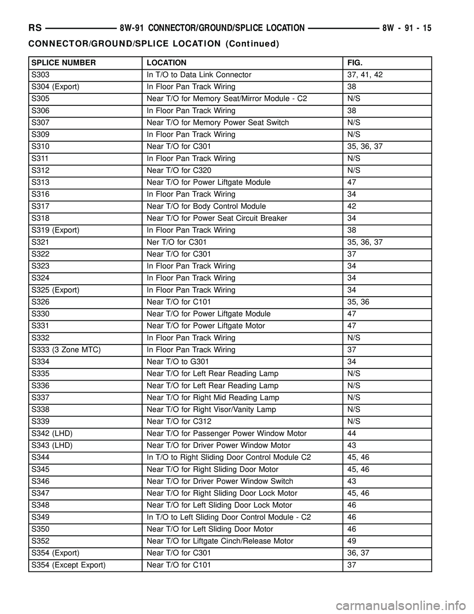
SPLICE NUMBER LOCATION FIG.
S303 In T/O to Data Link Connector 37, 41, 42
S304 (Export) In Floor Pan Track Wiring 38
S305 Near T/O for Memory Seat/Mirror Module - C2 N/S
S306 In Floor Pan Track Wiring 38
S307 Near T/O for Memory Power Seat Switch N/S
S309 In Floor Pan Track Wiring N/S
S310 Near T/O for C301 35, 36, 37
S311 In Floor Pan Track Wiring N/S
S312 Near T/O for C320 N/S
S313 Near T/O for Power Liftgate Module 47
S316 In Floor Pan Track Wiring 34
S317 Near T/O for Body Control Module 42
S318 Near T/O for Power Seat Circuit Breaker 34
S319 (Export) In Floor Pan Track Wiring 38
S321 Ner T/O for C301 35, 36, 37
S322 Near T/O for C301 37
S323 In Floor Pan Track Wiring 34
S324 In Floor Pan Track Wiring 34
S325 (Export) In Floor Pan Track Wiring 34
S326 Near T/O for C101 35, 36
S330 Near T/O for Power Liftgate Module 47
S331 Near T/O for Power Liftgate Motor 47
S332 In Floor Pan Track Wiring N/S
S333 (3 Zone MTC) In Floor Pan Track Wiring 37
S334 Near T/O to G301 34
S335 Near T/O for Left Rear Reading Lamp N/S
S336 Near T/O for Left Rear Reading Lamp N/S
S337 Near T/O for Right Mid Reading Lamp N/S
S338 Near T/O for Right Visor/Vanity Lamp N/S
S339 Near T/O for C312 N/S
S342 (LHD) Near T/O for Passenger Power Window Motor 44
S343 (LHD) Near T/O for Driver Power Window Motor 43
S344 In T/O to Right Sliding Door Control Module C2 45, 46
S345 Near T/O for Right Sliding Door Motor 45, 46
S346 Near T/O for Driver Power Window Switch 43
S347 Near T/O for Right Sliding Door Lock Motor 45, 46
S348 Near T/O for Left Sliding Door Lock Motor 46
S349 In T/O to Left Sliding Door Control Module - C2 46
S350 Near T/O for Left Sliding Door Motor 46
S352 Near T/O for Liftgate Cinch/Release Motor 49
S354 (Export) Near T/O for C301 36, 37
S354 (Except Export) Near T/O for C101 37
RS8W-91 CONNECTOR/GROUND/SPLICE LOCATION8W-91-15
CONNECTOR/GROUND/SPLICE LOCATION (Continued)
Page 1129 of 2339
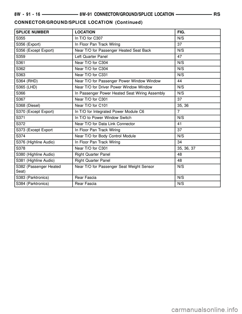
SPLICE NUMBER LOCATION FIG.
S355 In T/O for C307 N/S
S356 (Export) In Floor Pan Track Wiring 37
S356 (Except Export) Near T/O for Passenger Heated Seat Back N/S
S359 Left Quarter Panel 47
S361 Near T/O for C304 N/S
S362 Near T/O for C304 N/S
S363 Near T/O for C331 N/S
S364 (RHD) Near T/O for Passenger Power Window Window 44
S365 (LHD) Near T/O for Driver Power Window Window N/S
S366 In Passenger Power Heated Seat Wiring Assembly N/S
S367 Near T/O for C301 37
S368 (Diesel) Near T/O for C101 35, 36
S370 (Except Export) In T/O for Integrated Power Module C6 7
S371 In T/O to Power Window Switch N/S
S372 Near T/O for Data Link Connector 41
S373 (Except Export In Floor Pan Track Wiring 37
S374 Near T/O for Body Control Module N/S
S376 (Highline Audio) In Floor Pan Track Wiring 34
S378 Near T/O for C301 35, 36, 37
S380 (Highline Audio) Right Quarter Panel 48
S381 (Highline Audio) Right Quarter Panel 48
S382 (Passenger Heated
Seat)Near T/O for Passenger Seat Weight Sensor N/S
S383 (Parktronics) Rear Fascia N/S
S384 (Parktronics) Rear Fascia N/S
8W - 91 - 16 8W-91 CONNECTOR/GROUND/SPLICE LOCATIONRS
CONNECTOR/GROUND/SPLICE LOCATION (Continued)
Page 1135 of 2339
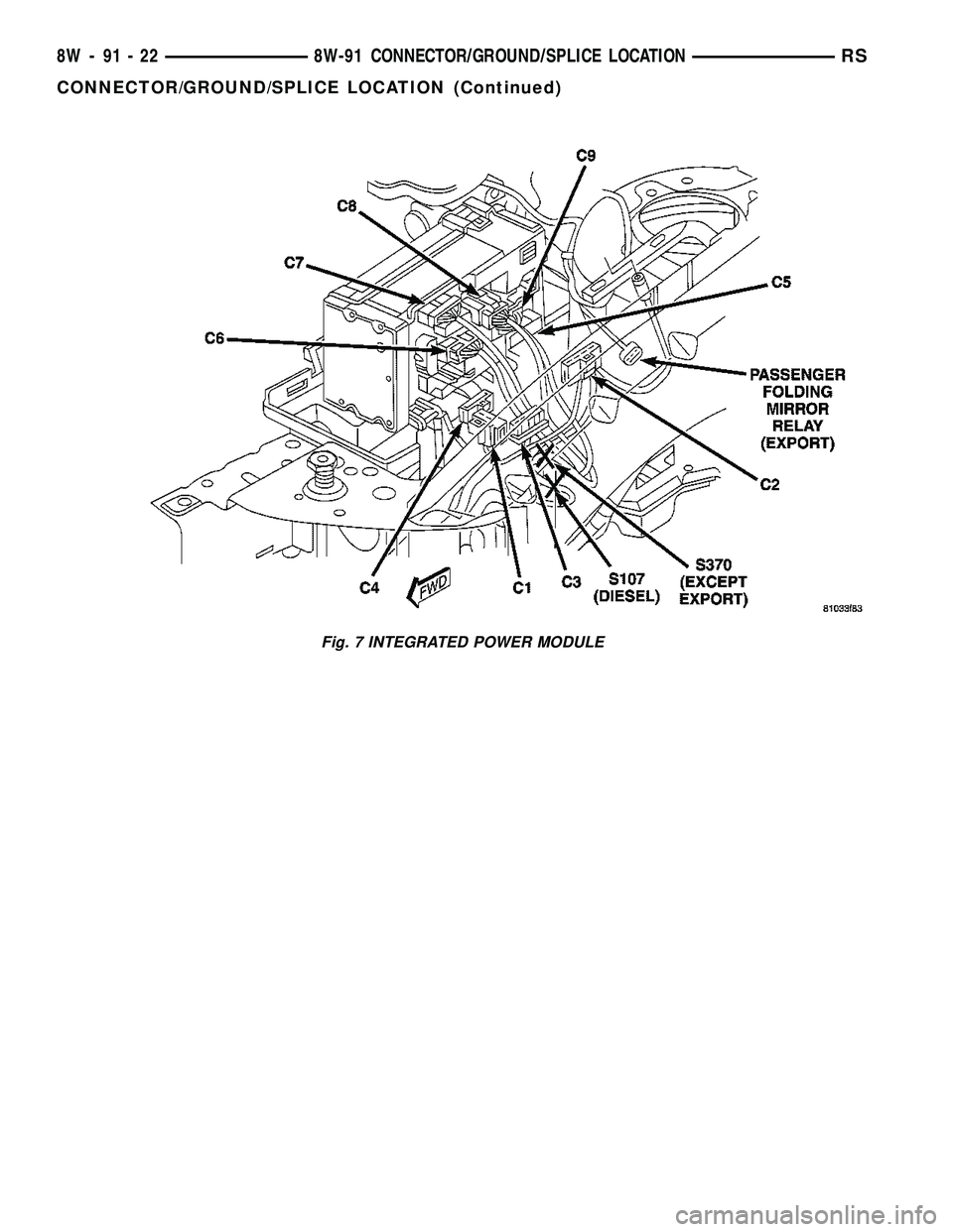
Fig. 7 INTEGRATED POWER MODULE
8W - 91 - 22 8W-91 CONNECTOR/GROUND/SPLICE LOCATIONRS
CONNECTOR/GROUND/SPLICE LOCATION (Continued)
Page 1169 of 2339
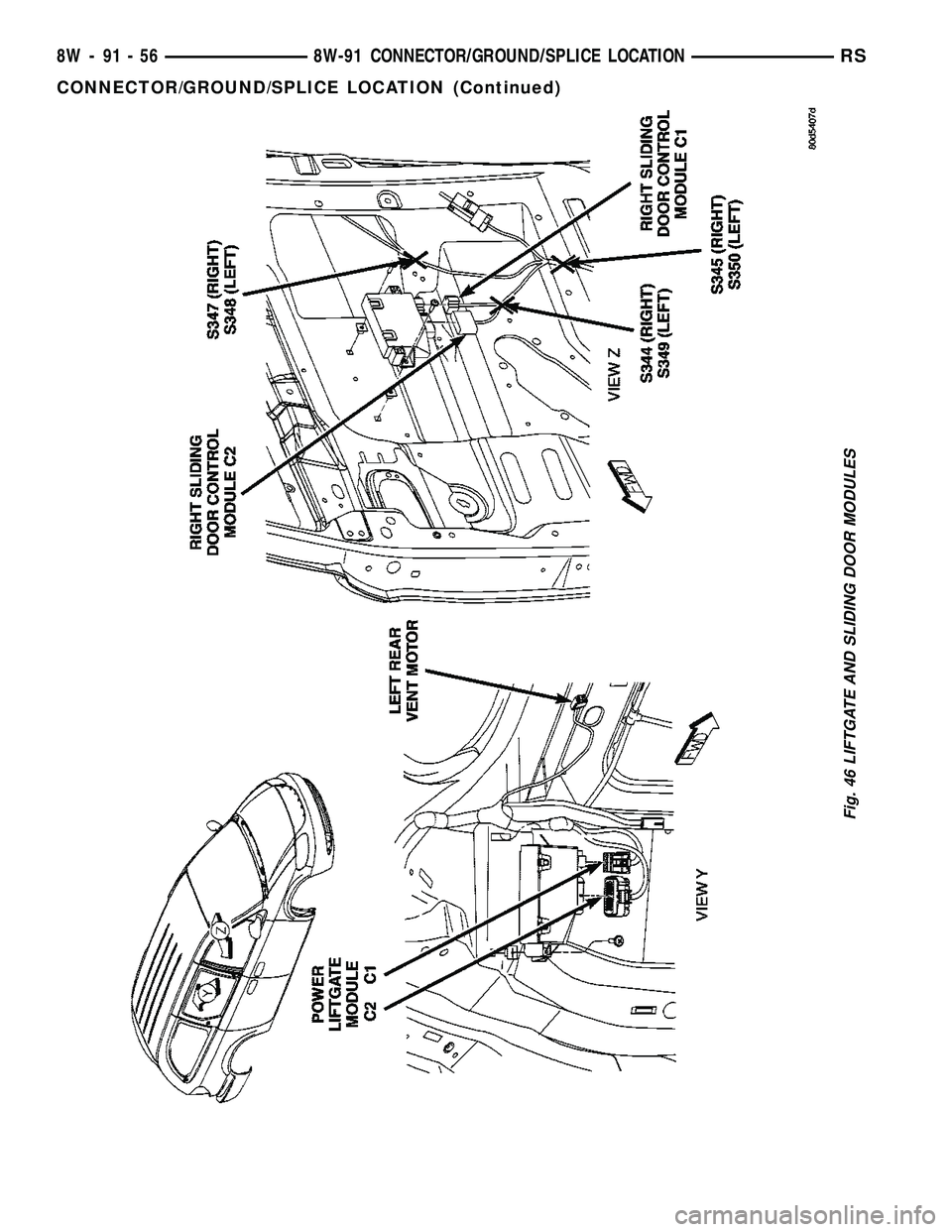
Fig. 46 LIFTGATE AND SLIDING DOOR MODULES
8W - 91 - 56 8W-91 CONNECTOR/GROUND/SPLICE LOCATIONRS
CONNECTOR/GROUND/SPLICE LOCATION (Continued)
Page 1174 of 2339
8W-97 POWER DISTRIBUTION SYSTEM
TABLE OF CONTENTS
page page
POWER DISTRIBUTION SYSTEM
DESCRIPTION..........................1
OPERATION............................1
SPECIAL TOOLS
POWER DISTRIBUTION SYSTEMS.........1
INTEGRATED POWER MODULE
DESCRIPTION..........................1
OPERATION............................2
REMOVAL.............................2
INSTALLATION..........................2IOD FUSE
DESCRIPTION..........................3
OPERATION............................3
POWER OUTLET
DESCRIPTION..........................3
OPERATION............................3
DIAGNOSIS AND TESTING
DIAGNOSIS & TESTING - POWER OUTLET . . 3
REMOVAL.............................4
INSTALLATION..........................4
POWER DISTRIBUTION
SYSTEM
DESCRIPTION
The power distribution system for this vehicle con-
sists of the following components:
²Integrated Power Module (IPM)
²Front Control Module (FCM)
²Power Outlets
Refer to Wiring Diagrams for complete circuit sche-
matics.
The power distribution system also incorporates
various types of circuit control and protection fea-
tures, including:
²Automatic resetting circuit breakers
²Blade-type fuses
²Bus bars
²Cartridge fuses
²Circuit splice blocks
²Flashers
²Fusible links
²Relays
OPERATION
The power distribution system for this vehicle is
designed to provide safe, reliable, and centralized dis-
tribution points for the electrical current required to
operate all of the many standard and optional facto-
ry-installed electrical and electronic powertrain,
chassis, safety, security, comfort and convenience sys-
tems. At the same time, the power distribution sys-
tem was designed to provide ready access to these
electrical distribution points for the vehicle techni-
cian to use when conducting diagnosis and repair of
faulty circuits. The power distribution system can
also prove useful for the sourcing of additional elec-
trical circuits that may be required to provide theelectrical current needed to operate many accessories
that the vehicle owner may choose to have installed.
SPECIAL TOOLS
POWER DISTRIBUTION SYSTEMS
INTEGRATED POWER MODULE
DESCRIPTION
The Integrated Power Module (IPM) is a combina-
tion of the Power Distribution Center (PDC) and the
Front Control Module (FCM). The IPM is located in
the engine compartment, next to the battery. (Fig. 1).
The PDC mates directly with the FCM to form the
IPM. The PDC is a printed circuit board based mod-
ule that contains fuses and relays, while the FCM
contains the electronics controlling the IPM and
other functions. This IPM connects directly to the
battery positive through a four pin connector. The
ground connection is through two other connectors.
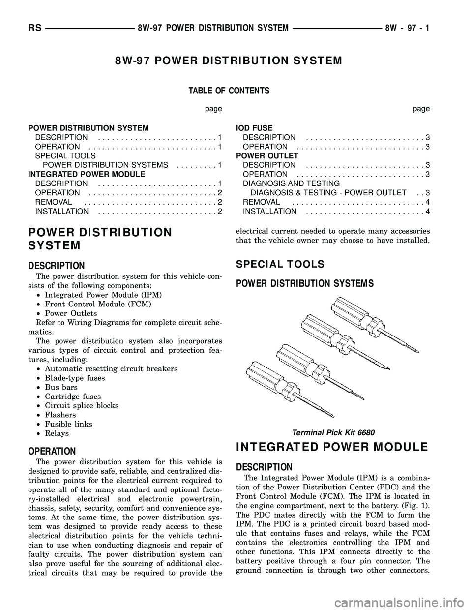
Terminal Pick Kit 6680
RS8W-97 POWER DISTRIBUTION SYSTEM8W-97-1