2005 CHRYSLER VOYAGER Module
[x] Cancel search: ModulePage 1395 of 2339
The PCM uses crankshaft position reference to
determine injector sequence, ignition timing and the
presence of misfire. Once the PCM determines crank-
shaft position, it begins energizing the injectors in
sequence.
REMOVAL
(1) Disconnect the negative battery cable.
(2) Raise vehicle and support.
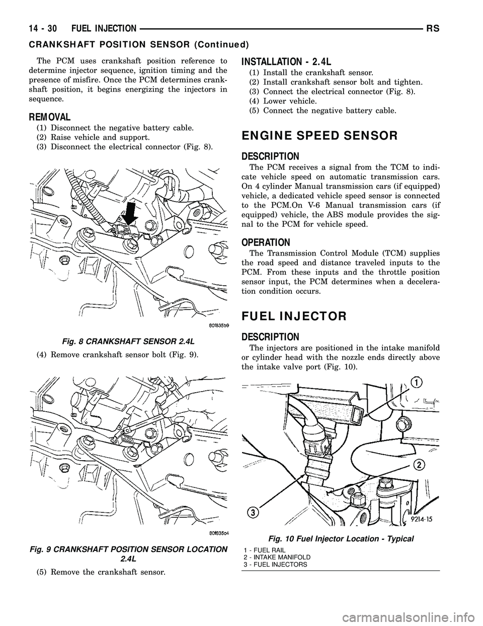
(3) Disconnect the electrical connector (Fig. 8).
(4) Remove crankshaft sensor bolt (Fig. 9).
(5) Remove the crankshaft sensor.
INSTALLATION - 2.4L
(1) Install the crankshaft sensor.
(2) Install crankshaft sensor bolt and tighten.
(3) Connect the electrical connector (Fig. 8).
(4) Lower vehicle.
(5) Connect the negative battery cable.
ENGINE SPEED SENSOR
DESCRIPTION
The PCM receives a signal from the TCM to indi-
cate vehicle speed on automatic transmission cars.
On 4 cylinder Manual transmission cars (if equipped)
vehicle, a dedicated vehicle speed sensor is connected
to the PCM.On V-6 Manual transmission cars (if
equipped) vehicle, the ABS module provides the sig-
nal to the PCM for vehicle speed.
OPERATION
The Transmission Control Module (TCM) supplies
the road speed and distance traveled inputs to the
PCM. From these inputs and the throttle position
sensor input, the PCM determines when a decelera-
tion condition occurs.
FUEL INJECTOR
DESCRIPTION
The injectors are positioned in the intake manifold
or cylinder head with the nozzle ends directly above
the intake valve port (Fig. 10).Fig. 8 CRANKSHAFT SENSOR 2.4L
Fig. 9 CRANKSHAFT POSITION SENSOR LOCATION
2.4L
Fig. 10 Fuel Injector Location - Typical
1 - FUEL RAIL
2 - INTAKE MANIFOLD
3 - FUEL INJECTORS
14 - 30 FUEL INJECTIONRS
CRANKSHAFT POSITION SENSOR (Continued)
Page 1405 of 2339
A (factory adjusted) set screw is used to mechani-
cally limit the position of the throttle body throttle
plate.Never attempt to adjust the engine idle
speed using this screw.All idle speed functions are
controlled by the PCM.
REMOVAL
(1) Disconnect negative cable from battery cable.
(2) Remove air inlet to throttle body hose clamp.
(3) Remove throttle and the speed control (if
equipped) cables from lever and bracket.
(4) Disconnect electrical connectors from the idle
air control motor and throttle position sensor (TPS)
(Fig. 28) or (Fig. 29).
(5) Remove throttle body to intake manifold
attaching bolts.
(6) Remove throttle body and gasket.
INSTALLATION
(1) Install a new gasket, if required.
(2) Install throttle body.
(3) Tighten throttle body mounting bolts. The 2.4L
to 28.2 N´m (250 50 in. lbs.) torque, The 3.3/3.8L to
11.6 N´m (105 20 in. lbs.) torque.
(4) Connect electrical connectors to the idle air
control motor and throttle position sensor (TPS) (Fig.
28) or (Fig. 29).
(5) Install air inlet to throttle body hose clamp and
tighten.
(6) Connect negative cable to battery cable.
THROTTLE CONTROL CABLE
REMOVAL
(1) Working from the engine compartment, hold
the throttle body throttle lever in the wide open posi-
tion.
(2) Remove the throttle cable from the throttle
body cam.
(3) From inside the vehicle, hold up the pedal and
remove the cable retainer and throttle cable from the
upper end of the pedal shaft.
(4) Remove retainer clip from throttle cable and
grommet at dash panel.
(5) From the engine compartment, pull the throttle
cable and gromment out of the dash panel.
(6) Remove the throttle cable from throttle bracket
by carefully compressing both retaining ears simulta-
neously then gently pull the throttle cable from
throttle bracket or if it is the slide snap design you
have to slide the locking tab out of the hole and then
slide the cable assembly out of the bracket.
INSTALLATION
(1) From the engine compartment, push the hous-
ing end fitting and grommet into the dash panel.In-
stall gromment into the dash panel.
(2) Install the cable housing (throttle body end)
into the cable mounting bracket on the engine.
(3) From inside the vehicle, hold up the pedal and
install throttle cable and cable retainer in the upper
end of the pedal shaft.
(4) At the dash panel, install the cable retainer
clip between the end of the throttle cable fitting and
grommet
(5) From the engine compartment, rotate the
throttle lever wide open and install the throttle
cable.
THROTTLE POSITION SENSOR
DESCRIPTION
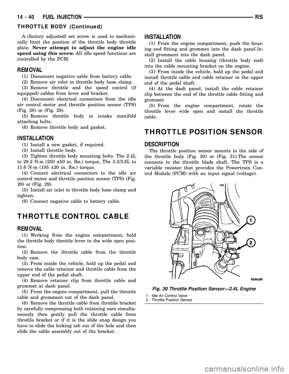
The throttle position sensor mounts to the side of
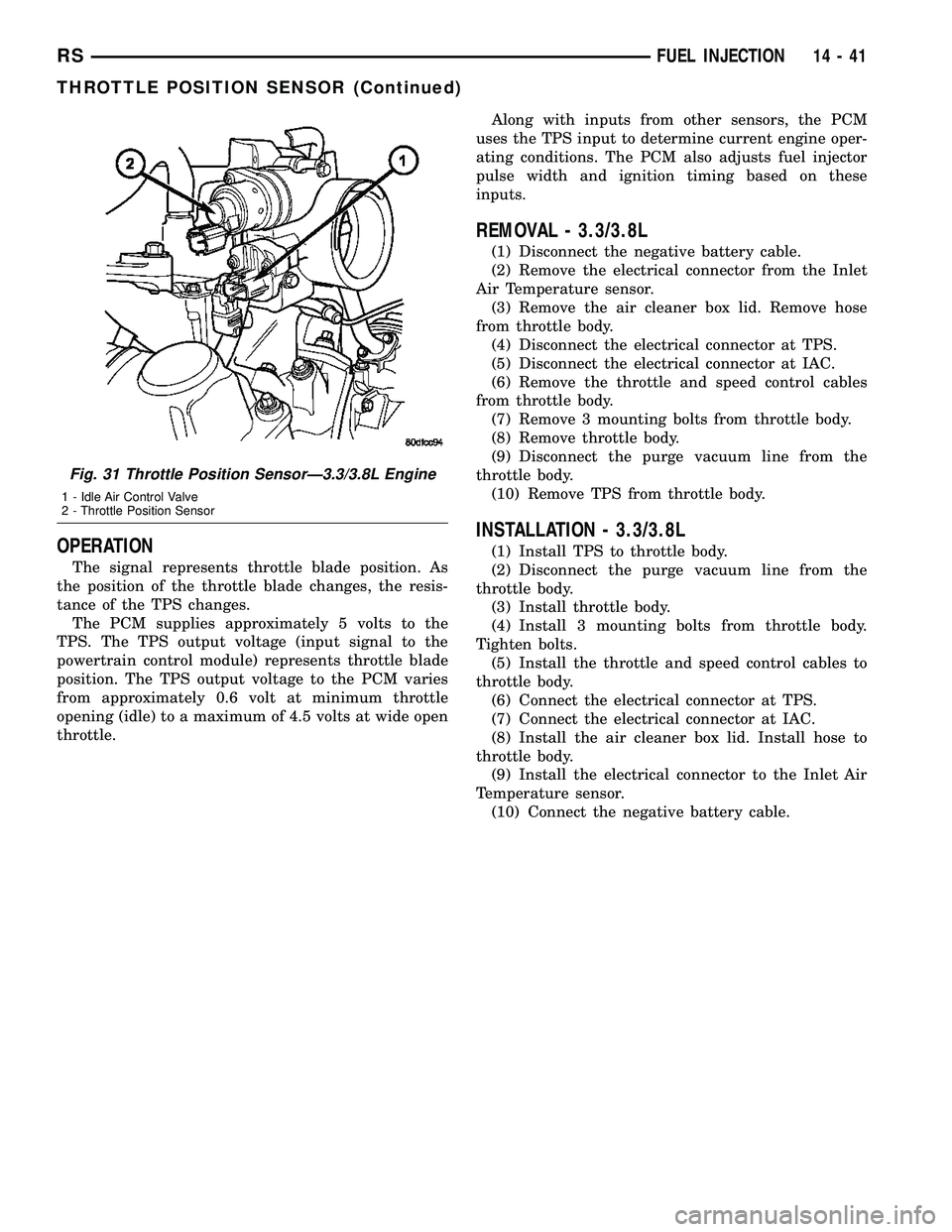
the throttle body (Fig. 30) or (Fig. 31).The sensor
connects to the throttle blade shaft. The TPS is a
variable resistor that provides the Powertrain Con-
trol Module (PCM) with an input signal (voltage).
Fig. 30 Throttle Position SensorÐ2.4L Engine
1 - Idle Air Control Valve
2 - Throttle Position Sensor
14 - 40 FUEL INJECTIONRS
THROTTLE BODY (Continued)
Page 1406 of 2339
OPERATION
The signal represents throttle blade position. As
the position of the throttle blade changes, the resis-
tance of the TPS changes.
The PCM supplies approximately 5 volts to the
TPS. The TPS output voltage (input signal to the
powertrain control module) represents throttle blade
position. The TPS output voltage to the PCM varies
from approximately 0.6 volt at minimum throttle
opening (idle) to a maximum of 4.5 volts at wide open
throttle.Along with inputs from other sensors, the PCM
uses the TPS input to determine current engine oper-
ating conditions. The PCM also adjusts fuel injector
pulse width and ignition timing based on these
inputs.
REMOVAL - 3.3/3.8L
(1) Disconnect the negative battery cable.
(2) Remove the electrical connector from the Inlet
Air Temperature sensor.
(3) Remove the air cleaner box lid. Remove hose
from throttle body.
(4) Disconnect the electrical connector at TPS.
(5) Disconnect the electrical connector at IAC.
(6) Remove the throttle and speed control cables
from throttle body.
(7) Remove 3 mounting bolts from throttle body.
(8) Remove throttle body.
(9) Disconnect the purge vacuum line from the
throttle body.
(10) Remove TPS from throttle body.
INSTALLATION - 3.3/3.8L
(1) Install TPS to throttle body.
(2) Disconnect the purge vacuum line from the
throttle body.
(3) Install throttle body.
(4) Install 3 mounting bolts from throttle body.
Tighten bolts.
(5) Install the throttle and speed control cables to
throttle body.
(6) Connect the electrical connector at TPS.
(7) Connect the electrical connector at IAC.
(8) Install the air cleaner box lid. Install hose to
throttle body.
(9) Install the electrical connector to the Inlet Air
Temperature sensor.
(10) Connect the negative battery cable.
Fig. 31 Throttle Position SensorÐ3.3/3.8L Engine
1 - Idle Air Control Valve
2 - Throttle Position Sensor
RSFUEL INJECTION14-41
THROTTLE POSITION SENSOR (Continued)
Page 1421 of 2339
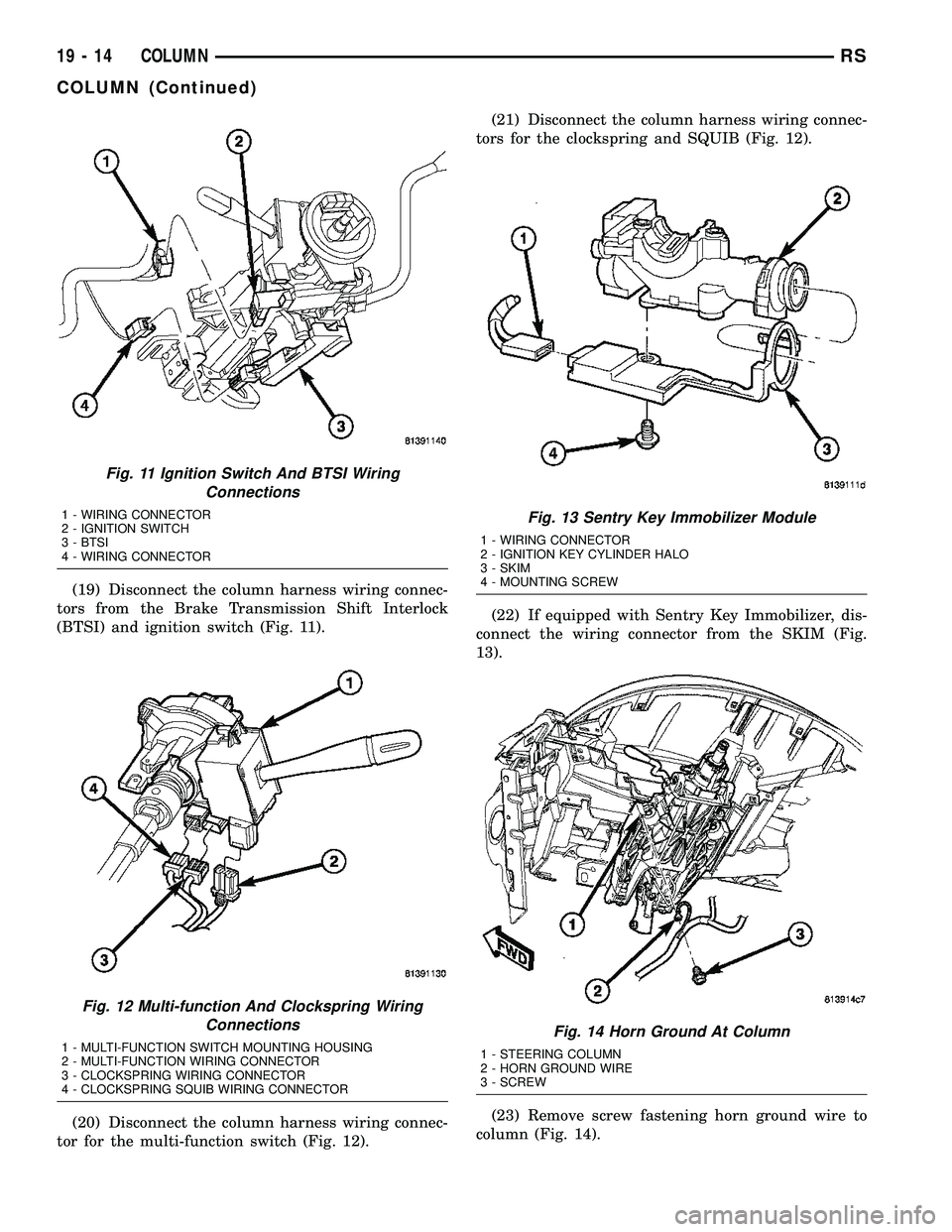
(19) Disconnect the column harness wiring connec-
tors from the Brake Transmission Shift Interlock
(BTSI) and ignition switch (Fig. 11).
(20) Disconnect the column harness wiring connec-
tor for the multi-function switch (Fig. 12).(21) Disconnect the column harness wiring connec-
tors for the clockspring and SQUIB (Fig. 12).
(22) If equipped with Sentry Key Immobilizer, dis-
connect the wiring connector from the SKIM (Fig.
13).
(23) Remove screw fastening horn ground wire to
column (Fig. 14).
Fig. 11 Ignition Switch And BTSI Wiring
Connections
1 - WIRING CONNECTOR
2 - IGNITION SWITCH
3 - BTSI
4 - WIRING CONNECTOR
Fig. 12 Multi-function And Clockspring Wiring
Connections
1 - MULTI-FUNCTION SWITCH MOUNTING HOUSING
2 - MULTI-FUNCTION WIRING CONNECTOR
3 - CLOCKSPRING WIRING CONNECTOR
4 - CLOCKSPRING SQUIB WIRING CONNECTOR
Fig. 13 Sentry Key Immobilizer Module
1 - WIRING CONNECTOR
2 - IGNITION KEY CYLINDER HALO
3 - SKIM
4 - MOUNTING SCREW
Fig. 14 Horn Ground At Column
1 - STEERING COLUMN
2 - HORN GROUND WIRE
3 - SCREW
19 - 14 COLUMNRS
COLUMN (Continued)
Page 1447 of 2339
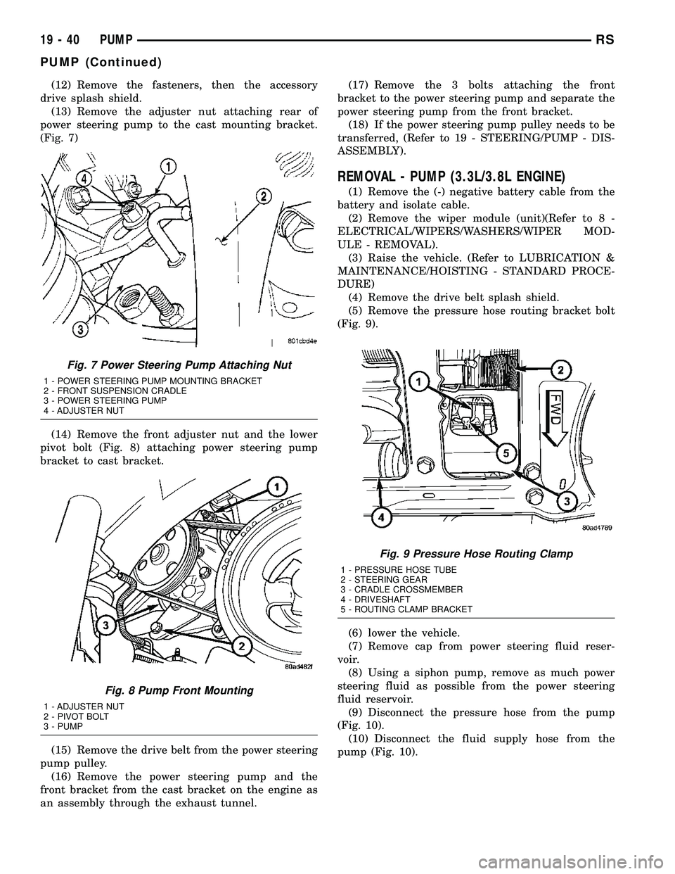
(12) Remove the fasteners, then the accessory
drive splash shield.
(13) Remove the adjuster nut attaching rear of
power steering pump to the cast mounting bracket.
(Fig. 7)
(14) Remove the front adjuster nut and the lower
pivot bolt (Fig. 8) attaching power steering pump
bracket to cast bracket.
(15) Remove the drive belt from the power steering
pump pulley.
(16) Remove the power steering pump and the
front bracket from the cast bracket on the engine as
an assembly through the exhaust tunnel.(17) Remove the 3 bolts attaching the front
bracket to the power steering pump and separate the
power steering pump from the front bracket.
(18) If the power steering pump pulley needs to be
transferred, (Refer to 19 - STEERING/PUMP - DIS-
ASSEMBLY).
REMOVAL - PUMP (3.3L/3.8L ENGINE)
(1) Remove the (-) negative battery cable from the
battery and isolate cable.
(2) Remove the wiper module (unit)(Refer to 8 -
ELECTRICAL/WIPERS/WASHERS/WIPER MOD-
ULE - REMOVAL).
(3) Raise the vehicle. (Refer to LUBRICATION &
MAINTENANCE/HOISTING - STANDARD PROCE-
DURE)
(4) Remove the drive belt splash shield.
(5) Remove the pressure hose routing bracket bolt
(Fig. 9).
(6) lower the vehicle.
(7) Remove cap from power steering fluid reser-
voir.
(8) Using a siphon pump, remove as much power
steering fluid as possible from the power steering
fluid reservoir.
(9) Disconnect the pressure hose from the pump
(Fig. 10).
(10) Disconnect the fluid supply hose from the
pump (Fig. 10).
Fig. 7 Power Steering Pump Attaching Nut
1 - POWER STEERING PUMP MOUNTING BRACKET
2 - FRONT SUSPENSION CRADLE
3 - POWER STEERING PUMP
4 - ADJUSTER NUT
Fig. 8 Pump Front Mounting
1 - ADJUSTER NUT
2 - PIVOT BOLT
3 - PUMP
Fig. 9 Pressure Hose Routing Clamp
1 - PRESSURE HOSE TUBE
2 - STEERING GEAR
3 - CRADLE CROSSMEMBER
4 - DRIVESHAFT
5 - ROUTING CLAMP BRACKET
19 - 40 PUMPRS
PUMP (Continued)
Page 1450 of 2339
INSTALLATION
INSTALLATION - PUMP (2.4L ENGINE)
(1) Install power steering pump back in vehicle
using the reverse order of its removal through the
exhaust tunnel of the vehicle.
(2) Install the power steering pump on its cast
mounting bracket (Fig. 7), then install the nut and
bolt attaching the front bracket to the cast bracket
(Fig. 8).Do not fully tighten at this time..
(3) Install the rear nut (Fig. 7).
(4) Install the power steering pump drive belt on
pulley and adjust (Refer to 7 - COOLING/ACCES-
SORY DRIVE/DRIVE BELTS - INSTALLATION).
(5) Tighten the two adjustment slot bolts and the
one pivot bolt to 54 N´m (40 ft. lbs.) torque.
(6) Install the accessory drive splash shield.
NOTE: Before installing power steering fluid pres-
sure hose on power steering pump, inspect the
O-ring on the pressure hose for damage and
replace if necessary.
(7) Install the power steering fluid pressure line
onto the output fitting of the power steering pump
(Fig. 6). Tighten the pressure line to pump fitting
tube nut to a torque of 31 N´m (275 in. lbs.).
(8) Install the power steering fluid low pressure
return hose on the power steering pump low pressure
fitting (Fig. 6).Be sure hose clamps are properly
reinstalled.
(9) Install the power steering fluid supply hose on
the power steering pump fluid fitting.Be sure hose
is clear of accessory drive belts all hose clamps
are properly reinstalled.
CAUTION: Heat sleeve must cover entire rubber
portion of return hose to ensure desired thermal
protection from exhaust.
(10) Properly position the protective heat sleeve
over the power steering return hose. Securely tie
strap the heat sleeve to the power steering hose to
keep in it's proper position.
(11)
Install the exhaust system (Fig. 4). Install all
exhaust system isolators/hangers on the exhaust sys-
tem brackets, then the four bolts and flag nuts (Fig. 3).
(12) Connect the oxygen sensor wiring harness to
the vehicle wiring harness.
(13) Lower vehicle.
(14) Connect the negative battery cable on the
negative battery post.
(15) Perform the POWER STEERING PUMP INI-
TIAL OPERATION procedure to properly fill and
bleed the power steering system. (Refer to 19 -
STEERING/PUMP - STANDARD PROCEDURE)
(16) Inspect for leaks.
INSTALLATION - PUMP (3.3L/3.8L ENGINE)
(1) Install power steering pump back in vehicle
using the reverse order of its removal through the
engine compartment of the vehicle.
(2) Install the power steering pump on its mount-
ing bracket.
(3) Install the 3 front power steering pump mount-
ing bolts (Fig. 11). Tighten the 3 front power steering
pump mounting bolts to a torque of 54 N´m (40 ft.
lbs.).
NOTE: Before installing power steering pressure
hose on power steering pump, inspect the O-ring
on the power steering pressure hose for damage
and replace if required.
(4) Install the power steering fluid pressure line
into the pressure output fitting of the power steering
pump (Fig. 10).Do not fully tighten tube nut at
this time.
(5) Install the power steering fluid supply hose on
the power steering pump supply fitting (Fig. 10).Be
sure hose clamp is properly installed.
(6) Raise the vehicle.
(7) Install the routing clip on the engine for the
pressure hose (Fig. 9) and tighten fastener.
(8) Install the serpentine drive belt (Refer to 7 -
COOLING/ACCESSORY DRIVE/DRIVE BELTS -
INSTALLATION).
(9) Install the drive belt splash shield.
(10) Lower the vehicle.
(11) Tighten the pressure line to pump pressure
fitting tube nut to a torque of 31 N´m (275 in. lbs.).
(12) Install the wiper module (unit)(Refer to 8 -
ELECTRICAL/WIPERS/WASHERS/WIPER MOD-
ULE - INSTALLATION).
(13) Connect the negative battery cable on the
negative battery post.
(14) Fill and bleed the power steering system
using the Power Steering Pump Initial Operation
Procedure (Refer to 19 - STEERING/PUMP - STAN-
DARD PROCEDURE).
(15) Inspect for leaks.
INSTALLATION - PUMP (DIESEL)
(1) Install the power steering pump on its cast
mounting bracket.
(2) Install the three front power steering pump
mounting bolts. Tighten the mounting bolts to a
torque of 54 N´m (40 ft. lbs.).
(3) Install the rear mounting bolt fastening the
stamped bracket to the cast bracket (Fig. 13).
Tighten the mounting bolt to a torque of 54 N´m (40
ft. lbs.).
RSPUMP19-43
PUMP (Continued)
Page 1463 of 2339
SPEED SENSOR - INPUT
DESCRIPTION........................120
OPERATION..........................120
REMOVAL............................121
INSTALLATION........................121
SPEED SENSOR - OUTPUT
DESCRIPTION........................122
OPERATION..........................122
REMOVAL............................123
INSTALLATION........................123
TORQUE CONVERTER
DESCRIPTION........................124
OPERATION..........................128
REMOVAL............................129
INSTALLATION........................129TRANSMISSION CONTROL RELAY
DESCRIPTION........................130
OPERATION..........................130
TRANSMISSION RANGE SENSOR
DESCRIPTION........................130
OPERATION..........................131
REMOVAL............................131
INSTALLATION........................131
VALVE BODY
DESCRIPTION........................132
OPERATION..........................132
REMOVAL............................133
DISASSEMBLY........................135
ASSEMBLY...........................139
INSTALLATION........................144
40TE AUTOMATIC
TRANSAXLE
DESCRIPTION
The 40TE (Fig. 1) is a four-speed transaxle that is
a conventional hydraulic/mechanical assembly with
an integral differential, and is controlled with adap-
tive electronic controls and monitors. The hydraulic
system of the transaxle consists of the transaxle
fluid, fluid passages, hydraulic valves, and various
line pressure control components. An input clutch
assembly which houses the underdrive, overdrive,
and reverse clutches is used. It also utilizes separate
holding clutches: 2nd/4th gear and Low/Reverse. The
primary mechanical components of the transaxle con-
sist of the following:
²Three multiple disc input clutches
²Two multiple disc holding clutches
²Four hydraulic accumulators
²Two planetary gear sets
²Hydraulic oil pump
²Valve body²Solenoid/Pressure switch assembly
²Integral differential assembly
Control of the transaxle is accomplished by fully
adaptive electronics. Optimum shift scheduling is
accomplished through continuous real-time sensor
feedback information provided to the Powertrain
Control Module (PCM) or Transmission Control Mod-
ule (TCM).
The PCM/TCM is the heart of the electronic control
system and relies on information from various direct
and indirect inputs (sensors, switches, etc.) to deter-
mine driver demand and vehicle operating condi-
tions. With this information, the PCM/TCM can
calculate and perform timely and quality shifts
through various output or control devices (solenoid
pack, transmission control relay, etc.).
The PCM/TCM also performs certain self-diagnos-
tic functions and provides comprehensive information
(sensor data, DTC's, etc.) which is helpful in proper
diagnosis and repair. This information can be viewed
with the DRB scan tool.
21 - 2 40TE AUTOMATIC TRANSAXLERS
Page 1470 of 2339
DIAGNOSIS AND TESTING - TORQUE
CONVERTER HOUSING FLUID LEAKAGE
When diagnosing converter housing fluid leaks,
three actions must be taken before repair:
(1) Verify proper transmission fluid level.
(2) Verify that the leak originates from the con-
verter housing area and is transmission fluid.
(3) Determine the true source of the leak.
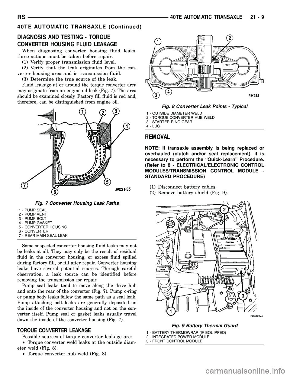
F
luid leakage at or around the torque converter area
may originate from an engine oil leak (Fig. 7). The area
should be examined closely. Factory fill fluid is red and,
therefore, can be distinguished from engine oil.
Some suspected converter housing fluid leaks may not
be leaks at all. They may only be the result of residual
fluid in the converter housing, or excess fluid spilled
during factory fill, or fill after repair. Converter housing
leaks have several potential sources. Through careful
observation, a leak source can be identified before
removing the transmission for repair.
Pump seal leaks tend to move along the drive hub
and onto the rear of the converter (Fig. 7). Pump o-ring
or pump body leaks follow the same path as a seal leak.
Pump attaching bolt leaks are generally deposited on
the inside of the converter housing and not on the con-
verter itself. Pump seal or gasket leaks usually travel
down the inside of the converter housing (Fig. 7).
TORQUE CONVERTER LEAKAGE
Possible sources of torque converter leakage are:
²Torque converter weld leaks at the outside diam-
eter weld (Fig. 8).
²Torque converter hub weld (Fig. 8).
REMOVAL
NOTE: If transaxle assembly is being replaced or
overhauled (clutch and/or seal replacement), it is
necessary to perform the ªQuick-Learnº Procedure.
(Refer to 8 - ELECTRICAL/ELECTRONIC CONTROL
MODULES/TRANSMISSION CONTROL MODULE -
STANDARD PROCEDURE)
(1) Disconnect battery cables.
(2) Remove battery shield (Fig. 9).
Fig. 7 Converter Housing Leak Paths
1 - PUMP SEAL
2 - PUMP VENT
3 - PUMP BOLT
4 - PUMP GASKET
5 - CONVERTER HOUSING
6 - CONVERTER
7 - REAR MAIN SEAL LEAK
Fig. 8 Converter Leak Points - Typical
1 - OUTSIDE DIAMETER WELD
2 - TORQUE CONVERTER HUB WELD
3 - STARTER RING GEAR
4 - LUG
Fig. 9 Battery Thermal Guard
1 - BATTERY THERMOWRAP (IF EQUIPPED)
2 - INTEGRATED POWER MODULE
3 - FRONT CONTROL MODULE
RS40TE AUTOMATIC TRANSAXLE21-9
40TE AUTOMATIC TRANSAXLE (Continued)