2005 CHRYSLER VOYAGER Module
[x] Cancel search: ModulePage 1618 of 2339
(28) Obtain helper and/or transmission jack.
Secure transmission jack to transaxle assembly.
(29) Remove upper mount bracket from transaxle
(Fig. 14).
(30) Remove remaining transaxle bellhousing-to-
engine bolts.
(31) Remove transaxle assembly from vehicle.
DISASSEMBLY
NOTE: If transaxle is being overhauled (clutch
and/or seal replacement) or replaced, it is neces-
sary to perform the PCM/TCM Quick Learn Proce-
dure. (Refer to 8 - ELECTRICAL/ELECTRONIC
CONTROL MODULES/POWERTRAIN/TRANSMIS-
SION CONTROL MODULE - STANDARD PROCE-
DURE)
NOTE: This procedure does not include final drive
(differential) disassembly.
(1) Remove input and output speed sensors.
(2) Remove three (3) solenoid/pressure switch
assembly-to-case bolts.
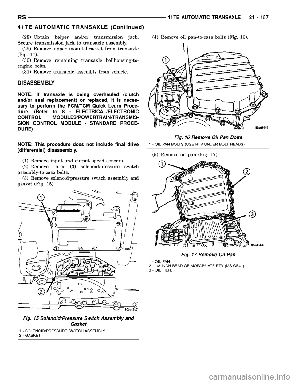
(3) Remove solenoid/pressure switch assembly and
gasket (Fig. 15).(4) Remove oil pan-to-case bolts (Fig. 16).
(5) Remove oil pan (Fig. 17).
Fig. 15 Solenoid/Pressure Switch Assembly and
Gasket
1 - SOLENOID/PRESSURE SWITCH ASSEMBLY
2 - GASKET
Fig. 16 Remove Oil Pan Bolts
1 - OIL PAN BOLTS (USE RTV UNDER BOLT HEADS)
Fig. 17 Remove Oil Pan
1 - OIL PAN
2 - 1/8 INCH BEAD OF MOPARTATF RTV (MS-GF41)
3 - OIL FILTER
RS41TE AUTOMATIC TRANSAXLE21 - 157
41TE AUTOMATIC TRANSAXLE (Continued)
Page 1635 of 2339
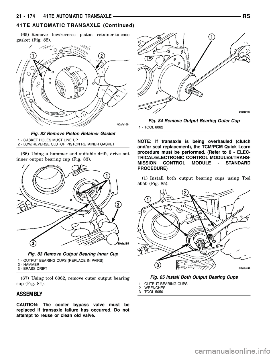
(65) Remove low/reverse piston retainer-to-case
gasket (Fig. 82).
(66) Using a hammer and suitable drift, drive out
inner output bearing cup (Fig. 83).
(67) Using tool 6062, remove outer output bearing
cup (Fig. 84).
ASSEMBLY
CAUTION: The cooler bypass valve must be
replaced if transaxle failure has occurred. Do not
attempt to reuse or clean old valve.NOTE: If transaxle is being overhauled (clutch
and/or seal replacement), the TCM/PCM Quick Learn
procedure must be performed. (Refer to 8 - ELEC-
TRICAL/ELECTRONIC CONTROL MODULES/TRANS-
MISSION CONTROL MODULE - STANDARD
PROCEDURE)
(1) Install both output bearing cups using Tool
5050 (Fig. 85).
Fig. 82 Remove Piston Retainer Gasket
1 - GASKET HOLES MUST LINE UP
2 - LOW/REVERSE CLUTCH PISTON RETAINER GASKET
Fig. 83 Remove Output Bearing Inner Cup
1 - OUTPUT BEARING CUPS (REPLACE IN PAIRS)
2 - HAMMER
3 - BRASS DRIFT
Fig. 84 Remove Output Bearing Outer Cup
1 - TOOL 6062
Fig. 85 Install Both Output Bearing Cups
1 - OUTPUT BEARING CUPS
2 - WRENCHES
3 - TOOL 5050
21 - 174 41TE AUTOMATIC TRANSAXLERS
41TE AUTOMATIC TRANSAXLE (Continued)
Page 1657 of 2339
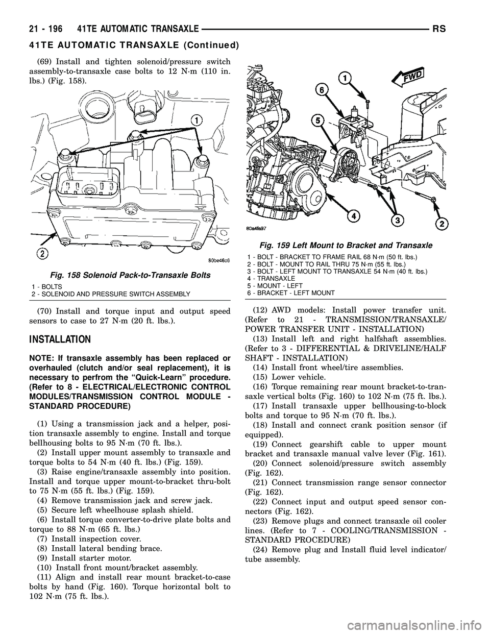
(69) Install and tighten solenoid/pressure switch
assembly-to-transaxle case bolts to 12 N´m (110 in.
lbs.) (Fig. 158).
(70) Install and torque input and output speed
sensors to case to 27 N´m (20 ft. lbs.).
INSTALLATION
NOTE: If transaxle assembly has been replaced or
overhauled (clutch and/or seal replacement), it is
necessary to perfrom the ªQuick-Learnº procedure.
(Refer to 8 - ELECTRICAL/ELECTRONIC CONTROL
MODULES/TRANSMISSION CONTROL MODULE -
STANDARD PROCEDURE)
(1) Using a transmission jack and a helper, posi-
tion transaxle assembly to engine. Install and torque
bellhousing bolts to 95 N´m (70 ft. lbs.).
(2) Install upper mount assembly to transaxle and
torque bolts to 54 N´m (40 ft. lbs.) (Fig. 159).
(3) Raise engine/transaxle assembly into position.
Install and torque upper mount-to-bracket thru-bolt
to 75 N´m (55 ft. lbs.) (Fig. 159).
(4) Remove transmission jack and screw jack.
(5) Secure left wheelhouse splash shield.
(6) Install torque converter-to-drive plate bolts and
torque to 88 N´m (65 ft. lbs.)
(7) Install inspection cover.
(8) Install lateral bending brace.
(9) Install starter motor.
(10) Install front mount/bracket assembly.
(11) Align and install rear mount bracket-to-case
bolts by hand (Fig. 160). Torque horizontal bolt to
102 N´m (75 ft. lbs.).(12) AWD models: Install power transfer unit.
(Refer to 21 - TRANSMISSION/TRANSAXLE/
POWER TRANSFER UNIT - INSTALLATION)
(13) Install left and right halfshaft assemblies.
(Refer to 3 - DIFFERENTIAL & DRIVELINE/HALF
SHAFT - INSTALLATION)
(14) Install front wheel/tire assemblies.
(15) Lower vehicle.
(16) Torque remaining rear mount bracket-to-tran-
saxle vertical bolts (Fig. 160) to 102 N´m (75 ft. lbs.).
(17) Install transaxle upper bellhousing-to-block
bolts and torque to 95 N´m (70 ft. lbs.).
(18) Install and connect crank position sensor (if
equipped).
(19) Connect gearshift cable to upper mount
bracket and transaxle manual valve lever (Fig. 161).
(20) Connect solenoid/pressure switch assembly
(Fig. 162).
(21) Connect transmission range sensor connector
(Fig. 162).
(22) Connect input and output speed sensor con-
nectors (Fig. 162).
(23) Remove plugs and connect transaxle oil cooler
lines. (Refer to 7 - COOLING/TRANSMISSION -
STANDARD PROCEDURE)
(24) Remove plug and Install fluid level indicator/
tube assembly.
Fig. 158 Solenoid Pack-to-Transaxle Bolts
1 - BOLTS
2 - SOLENOID AND PRESSURE SWITCH ASSEMBLY
Fig. 159 Left Mount to Bracket and Transaxle
1 - BOLT - BRACKET TO FRAME RAIL 68 N´m (50 ft. lbs.)
2 - BOLT - MOUNT TO RAIL THRU 75 N´m (55 ft. lbs.)
3 - BOLT - LEFT MOUNT TO TRANSAXLE 54 N´m (40 ft. lbs.)
4 - TRANSAXLE
5 - MOUNT - LEFT
6 - BRACKET - LEFT MOUNT
21 - 196 41TE AUTOMATIC TRANSAXLERS
41TE AUTOMATIC TRANSAXLE (Continued)
Page 1726 of 2339
OPERATION
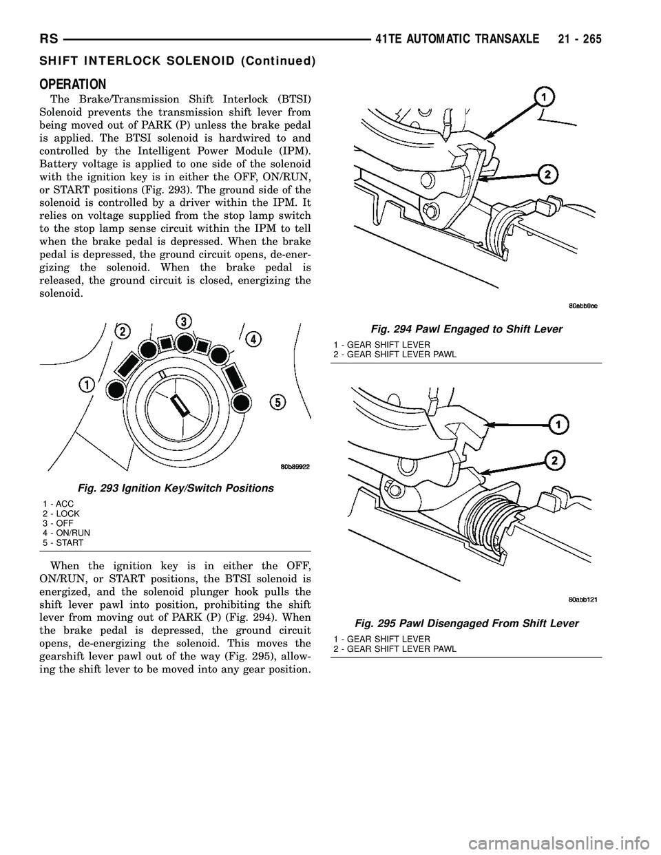
The Brake/Transmission Shift Interlock (BTSI)
Solenoid prevents the transmission shift lever from
being moved out of PARK (P) unless the brake pedal
is applied. The BTSI solenoid is hardwired to and
controlled by the Intelligent Power Module (IPM).
Battery voltage is applied to one side of the solenoid
with the ignition key is in either the OFF, ON/RUN,
or START positions (Fig. 293). The ground side of the
solenoid is controlled by a driver within the IPM. It
relies on voltage supplied from the stop lamp switch
to the stop lamp sense circuit within the IPM to tell
when the brake pedal is depressed. When the brake
pedal is depressed, the ground circuit opens, de-ener-
gizing the solenoid. When the brake pedal is
released, the ground circuit is closed, energizing the
solenoid.
When the ignition key is in either the OFF,
ON/RUN, or START positions, the BTSI solenoid is
energized, and the solenoid plunger hook pulls the
shift lever pawl into position, prohibiting the shift
lever from moving out of PARK (P) (Fig. 294). When
the brake pedal is depressed, the ground circuit
opens, de-energizing the solenoid. This moves the
gearshift lever pawl out of the way (Fig. 295), allow-
ing the shift lever to be moved into any gear position.
Fig. 293 Ignition Key/Switch Positions
1 - ACC
2 - LOCK
3 - OFF
4 - ON/RUN
5-START
Fig. 294 Pawl Engaged to Shift Lever
1 - GEAR SHIFT LEVER
2 - GEAR SHIFT LEVER PAWL
Fig. 295 Pawl Disengaged From Shift Lever
1 - GEAR SHIFT LEVER
2 - GEAR SHIFT LEVER PAWL
RS41TE AUTOMATIC TRANSAXLE21 - 265
SHIFT INTERLOCK SOLENOID (Continued)
Page 1730 of 2339
should be detected by the PCM/TCM during this test.
It no spike is detected, the circuit is tested again to
verify the failure. In addition to the periodic testing,
the solenoid circuits are tested if a speed ratio or
pressure switch error occurs.
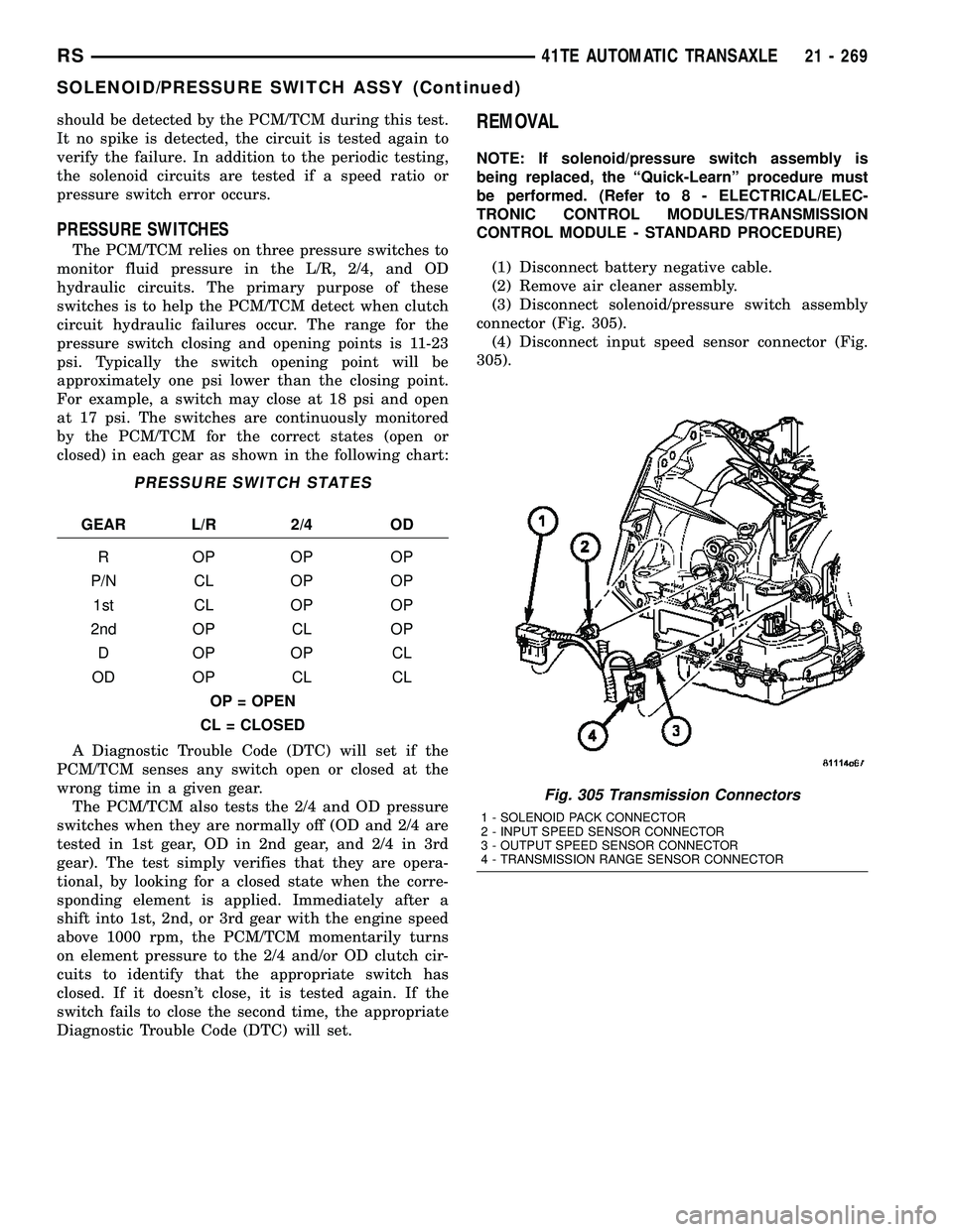
PRESSURE SWITCHES
The PCM/TCM relies on three pressure switches to
monitor fluid pressure in the L/R, 2/4, and OD
hydraulic circuits. The primary purpose of these
switches is to help the PCM/TCM detect when clutch
circuit hydraulic failures occur. The range for the
pressure switch closing and opening points is 11-23
psi. Typically the switch opening point will be
approximately one psi lower than the closing point.
For example, a switch may close at 18 psi and open
at 17 psi. The switches are continuously monitored
by the PCM/TCM for the correct states (open or
closed) in each gear as shown in the following chart:
PRESSURE SWITCH STATES
GEAR L/R 2/4 OD
ROPOPOP
P/N CL OP OP
1st CL OP OP
2nd OP CL OP
DOPOPCL
OD OP CL CL
OP = OPEN
CL = CLOSED
A Diagnostic Trouble Code (DTC) will set if the
PCM/TCM senses any switch open or closed at the
wrong time in a given gear.
The PCM/TCM also tests the 2/4 and OD pressure
switches when they are normally off (OD and 2/4 are
tested in 1st gear, OD in 2nd gear, and 2/4 in 3rd
gear). The test simply verifies that they are opera-
tional, by looking for a closed state when the corre-
sponding element is applied. Immediately after a
shift into 1st, 2nd, or 3rd gear with the engine speed
above 1000 rpm, the PCM/TCM momentarily turns
on element pressure to the 2/4 and/or OD clutch cir-
cuits to identify that the appropriate switch has
closed. If it doesn't close, it is tested again. If the
switch fails to close the second time, the appropriate
Diagnostic Trouble Code (DTC) will set.
REMOVAL
NOTE: If solenoid/pressure switch assembly is
being replaced, the ªQuick-Learnº procedure must
be performed. (Refer to 8 - ELECTRICAL/ELEC-
TRONIC CONTROL MODULES/TRANSMISSION
CONTROL MODULE - STANDARD PROCEDURE)
(1) Disconnect battery negative cable.
(2) Remove air cleaner assembly.
(3) Disconnect solenoid/pressure switch assembly
connector (Fig. 305).
(4) Disconnect input speed sensor connector (Fig.
305).
Fig. 305 Transmission Connectors
1 - SOLENOID PACK CONNECTOR
2 - INPUT SPEED SENSOR CONNECTOR
3 - OUTPUT SPEED SENSOR CONNECTOR
4 - TRANSMISSION RANGE SENSOR CONNECTOR
RS41TE AUTOMATIC TRANSAXLE21 - 269
SOLENOID/PRESSURE SWITCH ASSY (Continued)
Page 1731 of 2339
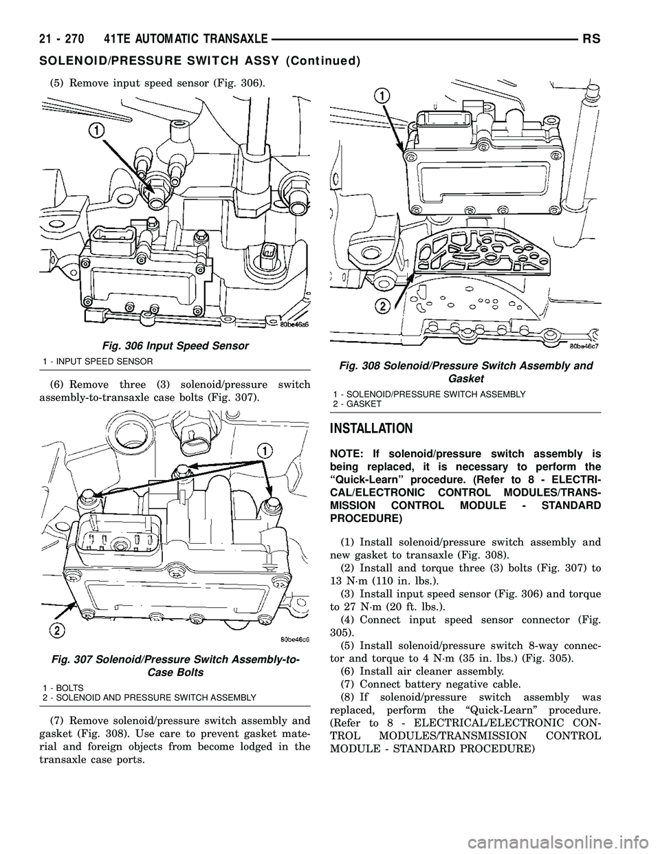
(5) Remove input speed sensor (Fig. 306).
(6) Remove three (3) solenoid/pressure switch
assembly-to-transaxle case bolts (Fig. 307).
(7) Remove solenoid/pressure switch assembly and
gasket (Fig. 308). Use care to prevent gasket mate-
rial and foreign objects from become lodged in the
transaxle case ports.
INSTALLATION
NOTE: If solenoid/pressure switch assembly is
being replaced, it is necessary to perform the
ªQuick-Learnº procedure. (Refer to 8 - ELECTRI-
CAL/ELECTRONIC CONTROL MODULES/TRANS-
MISSION CONTROL MODULE - STANDARD
PROCEDURE)
(1) Install solenoid/pressure switch assembly and
new gasket to transaxle (Fig. 308).
(2) Install and torque three (3) bolts (Fig. 307) to
13 N´m (110 in. lbs.).
(3) Install input speed sensor (Fig. 306) and torque
to 27 N´m (20 ft. lbs.).
(4) Connect input speed sensor connector (Fig.
305).
(5) Install solenoid/pressure switch 8-way connec-
tor and torque to 4 N´m (35 in. lbs.) (Fig. 305).
(6) Install air cleaner assembly.
(7) Connect battery negative cable.
(8) If solenoid/pressure switch assembly was
replaced, perform the ªQuick-Learnº procedure.
(Refer to 8 - ELECTRICAL/ELECTRONIC CON-
TROL MODULES/TRANSMISSION CONTROL
MODULE - STANDARD PROCEDURE)
Fig. 306 Input Speed Sensor
1 - INPUT SPEED SENSOR
Fig. 307 Solenoid/Pressure Switch Assembly-to-
Case Bolts
1 - BOLTS
2 - SOLENOID AND PRESSURE SWITCH ASSEMBLY
Fig. 308 Solenoid/Pressure Switch Assembly and
Gasket
1 - SOLENOID/PRESSURE SWITCH ASSEMBLY
2 - GASKET
21 - 270 41TE AUTOMATIC TRANSAXLERS
SOLENOID/PRESSURE SWITCH ASSY (Continued)
Page 1732 of 2339
SPEED SENSOR - INPUT
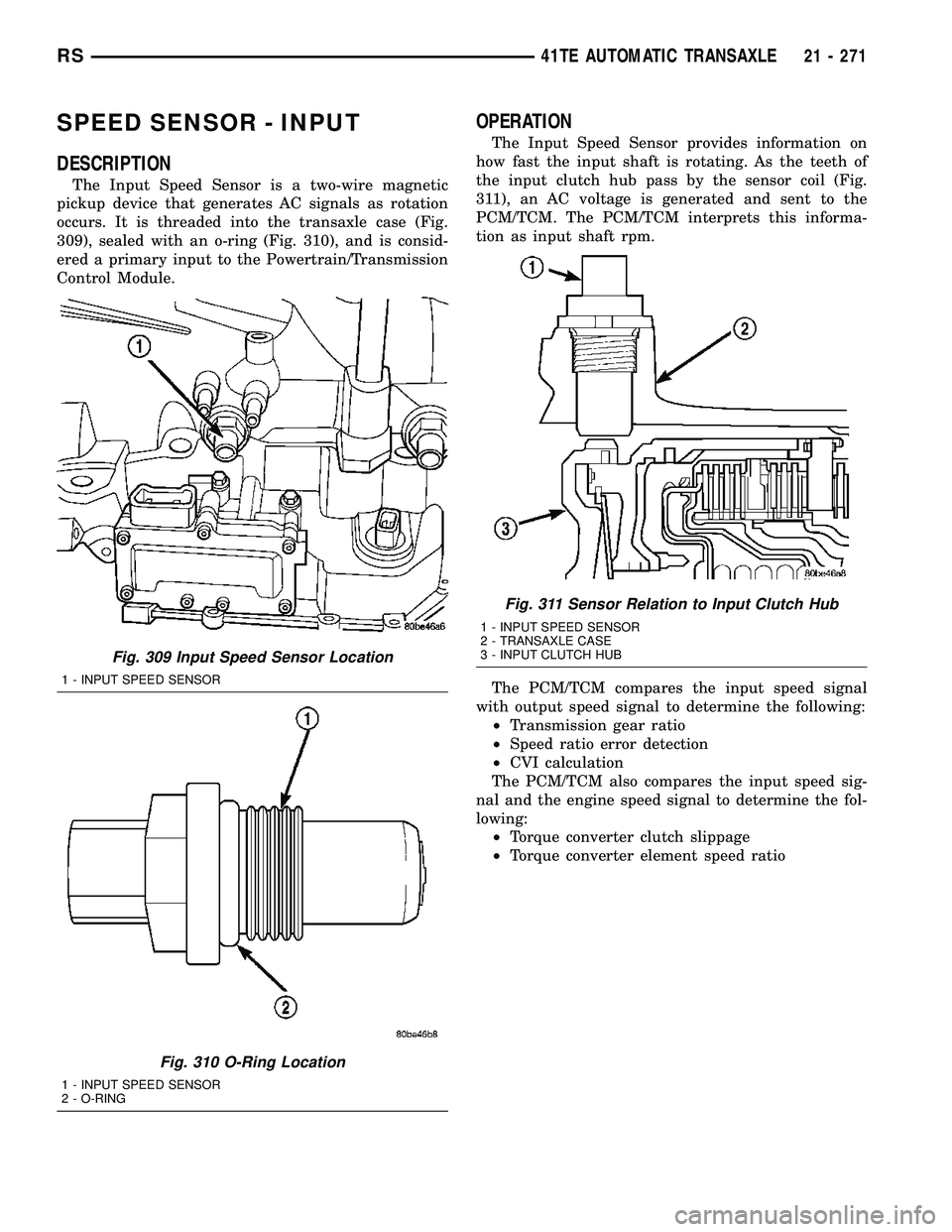
DESCRIPTION
The Input Speed Sensor is a two-wire magnetic
pickup device that generates AC signals as rotation
occurs. It is threaded into the transaxle case (Fig.
309), sealed with an o-ring (Fig. 310), and is consid-
ered a primary input to the Powertrain/Transmission
Control Module.
OPERATION
The Input Speed Sensor provides information on
how fast the input shaft is rotating. As the teeth of
the input clutch hub pass by the sensor coil (Fig.
311), an AC voltage is generated and sent to the
PCM/TCM. The PCM/TCM interprets this informa-
tion as input shaft rpm.
The PCM/TCM compares the input speed signal
with output speed signal to determine the following:
²Transmission gear ratio
²Speed ratio error detection
²CVI calculation
The PCM/TCM also compares the input speed sig-
nal and the engine speed signal to determine the fol-
lowing:
²Torque converter clutch slippage
²Torque converter element speed ratio
Fig. 309 Input Speed Sensor Location
1 - INPUT SPEED SENSOR
Fig. 310 O-Ring Location
1 - INPUT SPEED SENSOR
2 - O-RING
Fig. 311 Sensor Relation to Input Clutch Hub
1 - INPUT SPEED SENSOR
2 - TRANSAXLE CASE
3 - INPUT CLUTCH HUB
RS41TE AUTOMATIC TRANSAXLE21 - 271
Page 1734 of 2339
SPEED SENSOR - OUTPUT
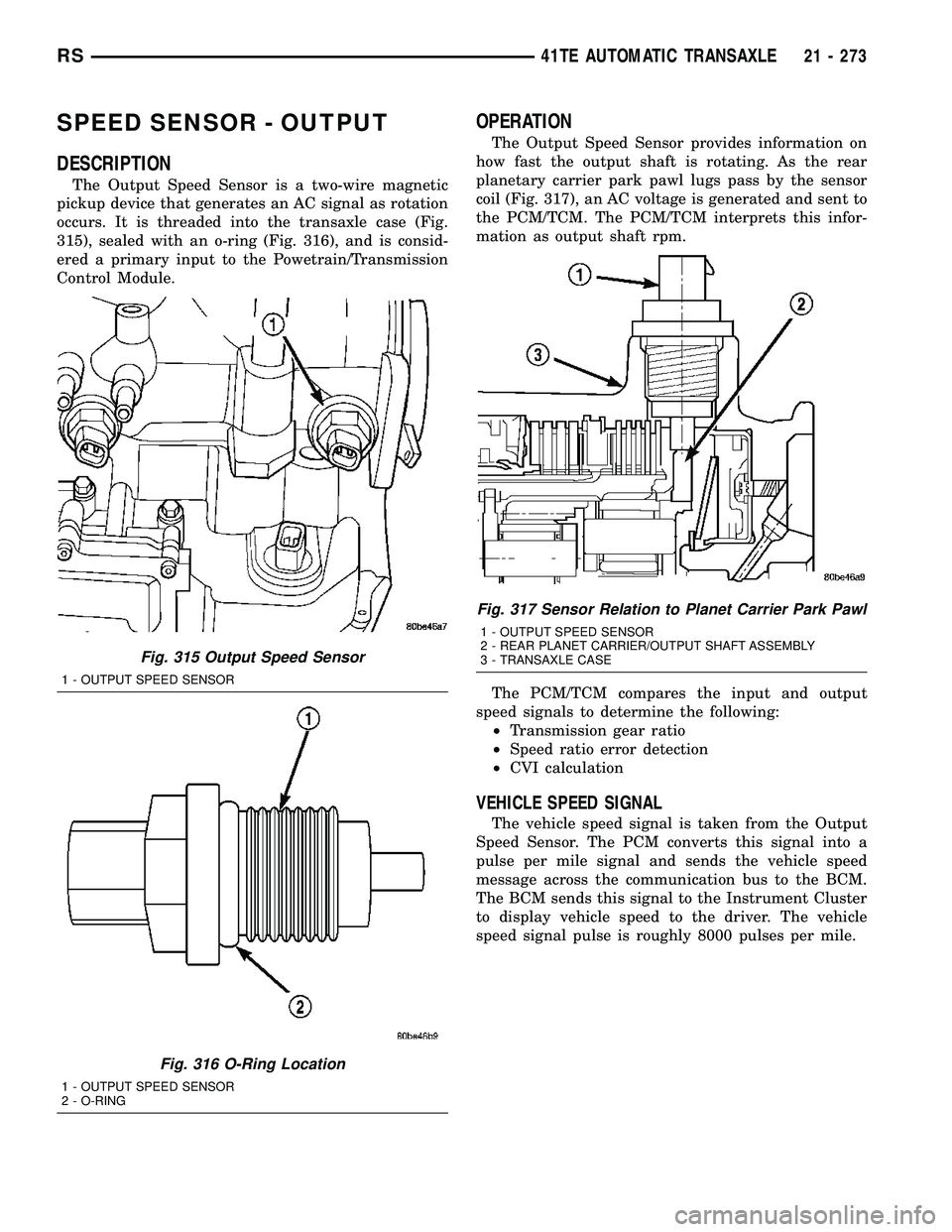
DESCRIPTION
The Output Speed Sensor is a two-wire magnetic
pickup device that generates an AC signal as rotation
occurs. It is threaded into the transaxle case (Fig.
315), sealed with an o-ring (Fig. 316), and is consid-
ered a primary input to the Powetrain/Transmission
Control Module.
OPERATION
The Output Speed Sensor provides information on
how fast the output shaft is rotating. As the rear
planetary carrier park pawl lugs pass by the sensor
coil (Fig. 317), an AC voltage is generated and sent to
the PCM/TCM. The PCM/TCM interprets this infor-
mation as output shaft rpm.
The PCM/TCM compares the input and output
speed signals to determine the following:
²Transmission gear ratio
²Speed ratio error detection
²CVI calculation
VEHICLE SPEED SIGNAL
The vehicle speed signal is taken from the Output
Speed Sensor. The PCM converts this signal into a
pulse per mile signal and sends the vehicle speed
message across the communication bus to the BCM.
The BCM sends this signal to the Instrument Cluster
to display vehicle speed to the driver. The vehicle
speed signal pulse is roughly 8000 pulses per mile.
Fig. 315 Output Speed Sensor
1 - OUTPUT SPEED SENSOR
Fig. 316 O-Ring Location
1 - OUTPUT SPEED SENSOR
2 - O-RING
Fig. 317 Sensor Relation to Planet Carrier Park Pawl
1 - OUTPUT SPEED SENSOR
2 - REAR PLANET CARRIER/OUTPUT SHAFT ASSEMBLY
3 - TRANSAXLE CASE
RS41TE AUTOMATIC TRANSAXLE21 - 273