2005 CHRYSLER VOYAGER Page 61
[x] Cancel search: Page 61Page 2249 of 2339
PLUMBING - REAR
TABLE OF CONTENTS
page page
A/C EVAPORATOR
DESCRIPTION.........................98
OPERATION...........................98
REMOVAL
REAR A/C EVAPORATOR...............98
REAR A/C EVAPORATOR LINE
EXTENSION.........................99
INSTALLATION
REAR A/C EVAPORATOR..............100
REAR A/C EVAPORATOR LINE
EXTENSION........................100
A/C EXPANSION VALVE
DESCRIPTION........................100
OPERATION..........................100
DIAGNOSIS AND TESTING
REAR A/C EXPANSION VALVE..........101
REMOVAL............................101
INSTALLATION........................101
HEATER CORE
DESCRIPTION........................102
OPERATION..........................102
STANDARD PROCEDURE
REAR HEATER CORE FILLING..........102REMOVAL............................103
INSTALLATION........................104
HEATER HOSES
REMOVAL............................104
INSTALLATION........................105
LIQUID LINE
REMOVAL............................105
INSTALLATION........................106
SUCTION LINE
REMOVAL............................106
INSTALLATION........................107
UNDERBODY LINES
DESCRIPTION........................108
OPERATION..........................108
REMOVAL
UNDERBODY HEATER TUBES..........109
UNDERBODY REFRIGERANT LINES......110
INSTALLATION
UNDERBODY HEATER TUBES..........112
UNDERBODY REFRIGERANT LINES......112
A/C EVAPORATOR
DESCRIPTION
The rear A/C evaporator is located in the rear
HVAC housing, behind the right rear wheel house.
The evaporator is positioned in the rear housing so
that all air that enters the housing must pass over
the fins of the evaporator coils before it is distributed
through the system ducts and outlets. However, air
passing over the evaporator fins will only be condi-
tioned when the compressor is engaged and circulat-
ing refrigerant through the evaporator tubes. The
rear HVAC housing must be removed from the vehi-
cle to access the A/C evaporator for service.
OPERATION
Refrigerant enters the rear evaporator from the
rear expansion valve as a low-temperature, low-pres-
sure liquid. As air flows over the fins of the evapora-
tor, the humidity in the air condenses on the fins,
and the heat from the air is absorbed by the refrig-
erant. Heat absorption causes the refrigerant to boil
and vaporize. The refrigerant becomes a low-pressure
gas when it leaves the evaporator.
REMOVAL
REAR A/C EVAPORATOR
WARNING: REFER TO THE APPLICABLE WARN-
INGS AND CAUTIONS FOR THIS SYSTEM BEFORE
PERFORMING THE FOLLOWING OPERATION (Refer
to 24 - HEATING & AIR CONDITIONING/PLUMBING -
FRONT - WARNING - A/C PLUMBING), (Refer to 24 -
HEATING & AIR CONDITIONING/PLUMBING -
FRONT - CAUTION - A/C PLUMBING), and (Refer to
24 - HEATING & AIR CONDITIONING/PLUMBING -
FRONT - WARNING - HEATER PLUMBING).
(1) Remove the rear HVAC housing from the vehi-
cle (Refer to 24 - HEATING & AIR CONDITIONING/
DISTRIBUTION/HVAC HOUSING - REMOVAL).
(2) Remove the rear evaporator line extension from
the expansion valve (Refer to 24 - HEATING & AIR
CONDITIONING/PLUMBING - REAR/EVAPORA-
TOR - REMOVAL - EVAPORATOR LINE EXTEN-
SION).
(3) Remove the rear expansion valve from the rear
evaporator (Refer to 24 - HEATING & AIR CONDI-
24 - 98 PLUMBING - REARRS
Page 2264 of 2339
CABIN HEATER
TABLE OF CONTENTS
page page
CABIN HEATER
DESCRIPTION........................113
OPERATION
MANUAL TEMPERATURE CONTROL
SYSTEM...........................113
AUTOMATIC TEMPERATURE CONTROL
SYSTEM...........................114
WARNING............................114
DIAGNOSIS AND TESTING
SUPPLEMENTAL CABIN HEATER........114
AIR INTAKE PIPE
REMOVAL............................115
INSTALLATION........................115
EXHAUST TUBE
REMOVAL............................116
INSTALLATION........................116
FUEL DOSING PUMP
DESCRIPTION........................117
OPERATION..........................117REMOVAL............................117
INSTALLATION........................117
FUEL LINE
STANDARD PROCEDURE
CLEANING..........................118
REMOVAL............................118
INSTALLATION........................118
HEATER HOSES
REMOVAL............................119
INSTALLATION........................119
HEATER PIPES
REMOVAL............................119
INSTALLATION........................120
HEATER UNIT
REMOVAL............................121
INSTALLATION........................122
HEATER WIRING
REMOVAL............................122
INSTALLATION........................122
CABIN HEATER
DESCRIPTION
Vehicles equipped with the diesel engine are also
equipped with a supplemental cabin heater. This
cabin heater is mounted under the vehicle and oper-
ates similar to an oil fired furnace. The heater burns
small amounts of fuel to provide additional heat to
the coolant. Coolant is routed from the engine, to the
supplemental cabin heater and then to the front
heater core. This provides additional heat to the pas-
senger compartment. The supplemental cabin heater
system is interfaced to the vehicles on-board com-
puter systems and DRBIIItdiagnostics.
The supplemental cabin heater has an electronic
control module that monitors the heat output of the
heater. The cabin heater operates at full load (5 kW),
half load or idle mode (no additional heat) depending
on engine coolant temperature.
When ambient temperatures are lower than 15É C
(60É F), the supplemental cabin heater automatically
operates once each ignition cycle for five minutes.
This assures a good fuel supply is always present for
the supplemental cabin heater.
OPERATION
MANUAL TEMPERATURE CONTROL SYSTEM
The supplemental cabin heater is activated via the
temperature slide control or knob on the A/C-heater
control when equipped with the manual temperature
control (MTC) system. If the slide control or knob is
moved to or above the upper set point the cabin
heater is activated. The cabin heater can operate in a
full or partial load range as well as an idle mode all
dependent on the engine coolant temperature. The
cabin heater will also turn off if the A/C-heater tem-
perature control is lowered to less than the lower set
point. The cabin heater can take up to three minutes
to completely shut down when either the heater tem-
perature is set below the lower set point or the vehi-
cle ignition is shut down.
NOTE: Do not apply a strong vacuum source such
as a garage ventilation system directly on the sup-
plemental cabin heater exhaust line. Too strong of a
vacuum can prevent the supplemental cabin heater
from starting. If required, place the vacuum source
at least 75 mm (3 in.) away from the exhaust line.
RSCABIN HEATER24 - 113
Page 2270 of 2339
NOTE: Verify that there is more than 1/8 of a tank of
fuel in the vehicle's fuel tank before performing this
procedure. Add fuel, if necessary.
NOTE: Failure to prime the dosing pump after drain-
ing the supplemental cabin fuel line will prevent
cabin heater activation during the first attempt to
start the cabin heater. This will also set a diagnostic
trouble code (DTC) in the cabin heater control's
memory. Do not perform the Dosing Pump Priming
procedure if an attempt was made to start the cabin
heater without priming the dosing pump first. This
will put excess fuel in the cabin heater and cause
smoke to emit from the cabin heater exhaust pipe
when cabin heater activation occurs.
(7) Connect the DRBIIItscan tool to the diagnos-
tic link connector.
(8) Turn the ignition to the ON position.
NOTE: Do not activate the dosing pump prime more
than one time. This will put excess fuel in the sup-
plemental cabin heater and cause smoke to emit
from the cabin heater exhaust pipe when cabin
heater activation occurs.
NOTE: A clicking noise heard coming from the dos-
ing pump indicates that the pump is operational.
(9) With the DRBIIItscan tool in Cabin Heater,
select System Tests and Dosing Pump Prime. Allow
the dosing pump to run for the full 45 second cycle
time. When the 45 second cycle is complete, press
Page Back on the DRBIIItscan tool key pad to exit
the Dosing Pump Prime. The Dosing Pump Priming
procedure is now complete.
HEATER HOSES
REMOVAL
(1) Raise and support the vehicle. Take note of the
location of the flexible section of the cabin heater
exhaust tube.
(2) Drain the engine cooling system (Refer to 7 -
COOLING - STANDARD PROCEDURE).
NOTE: Complete removal of the supplemental cabin
heater from vehicle is not required, lowering the
cabin heater allows easier access to coolant line
clamps.(3) Lower the supplemental cabin heater from the
vehicle (Refer to 24 - HEATING & AIR CONDITION-
ING/CABIN HEATER/HEATER UNIT - REMOVAL).
(4) Remove the clamps from both flexible coolant
line ends.
NOTE: It is recommended that both flexible cabin
heater coolant lines be replaced if either cabin
heater coolant line is damaged.
(5) Remove both coolant lines from vehicle.
INSTALLATION
(1) Install both flexible coolant lines to the supple-
mental cabin heater and install the clamps.
(2) Install the flexible coolant lines to the coolant
pipes and install the clamps.
(3) Install the supplemental cabin heater into the
vehicle (Refer to 24 - HEATING & AIR CONDITION-
ING/CABIN HEATER/HEATER UNIT - INSTALLA-
TION).
(4) Lower the vehicle.
(5) Fill the engine cooling system (Refer to 7 -
COOLING - STANDARD PROCEDURE).
(6) Verify operation of the supplemental cabin
heater.
HEATER PIPES
REMOVAL
WARNING: ALLOW THE ENGINE COOLING SYSTEM
TO COOL COMPLETELY BEFORE REMOVING RADI-
ATOR CAP OR DRAINING THE ENGINE COOLING
SYSTEM. PERSONAL INJURY MAY RESULT IF THE
ENGINE COOLING SYSTEM IS OPENED WHILE
ENGINE COOLANT IS HOT AND UNDER PRES-
SURE.
NOTE: Steel heater lines from engine compartment
to the supplemental cabin heater are part of an
assembly that includes the air intake pipe. If the
cabin heater lines or air intake pipe require removal
or replacement the entire cabin heater assembly
will require removal or replacement.
(1) Drain the engine cooling system (Refer to 7 -
COOLING - STANDARD PROCEDURE).
(2) Remove clamps from both the EGR cooler and
the lower heater port. Separate hoses from the mat-
ing plumbing port (Fig. 6).
RSCABIN HEATER24 - 119
FUEL LINE (Continued)
Page 2274 of 2339
EMISSIONS CONTROL
TABLE OF CONTENTS
page page
EMISSIONS CONTROL
DESCRIPTION
VEHICLE EMISSION CONTROL
INFORMATION LABEL...................1
TRIP DEFINITION......................1
DESCRIPTION - MONITORED COMPONENT . 1
NON-MONITORED CIRCUITS.............5
DESCRIPTION - MONITORED SYSTEMS....6HIGH AND LOW LIMITS.................9
OPERATION
SYSTEM.............................9
DRB IIITSTATE DISPLAY TEST MODE.....10
EVAPORATIVE EMISSIONS................11
EXHAUST GAS RECIRCULATION...........22
ON-BOARD DIAGNOSTICS................25
EMISSIONS CONTROL
DESCRIPTION
VEHICLE EMISSION CONTROL INFORMATION
LABEL
All models have a Vehicle Emission Control Infor-
mation (VECI) Label. Chrysler permanently attaches
the label in the engine compartment. It cannot be
removed without defacing information and destroying
the label.
The label contains the vehicle's emission specifica-
tions and vacuum hose routings. All hoses must be
connected and routed according to the label.
TRIP DEFINITION
A ªTripº means vehicle operation (following an
engine-off period) of duration and driving mode such
that all components and systems are monitored at
least once by the diagnostic system. The monitors
must successfully pass before the PCM can verify
that a previously malfunctioning component is meet-
ing the normal operating conditions of that compo-
nent. For misfire or fuel system malfunction, the
MIL may be extinguished if the fault does not recur
when monitored during three subsequent sequential
driving cycles in which conditions are similar to
those under which the malfunction was first deter-
mined.
Anytime the MIL is illuminated, a DTC is stored.
The DTC can self erase only after the MIL has been
extinguished. Once the MIL is extinguished, the
PCM must pass the diagnostic test for the most
recent DTC for 40 warm-up cycles (80 warm-up
cycles for the Fuel System Monitor and the Misfire
Monitor). A warm-up cycle can best be described by
the following:
²The engine must be running²A rise of 40ÉF in engine temperature must occur
from the time when the engine was started
²Engine coolant temperature must crossover
160ÉF
²A ªdriving cycleº that consists of engine start up
and engine shut off.
Once the above conditions occur, the PCM is con-
sidered to have passed a warm-up cycle. Due to the
conditions required to extinguish the MIL and erase
the DTC, it is most important that after a repair has
been made, all DTC's be erased and the repair veri-
fied by running 1±good trip.
DESCRIPTION - MONITORED COMPONENT
There are several components that will affect vehi-
cle emissions if they malfunction. If one of these com-
ponents malfunctions the Malfunction Indicator
Lamp (Check Engine) will illuminate.
Some of the component monitors are checking for
proper operation of the part. Electrically operated
components now have input (rationality) and output
(functionality) checks as well as continuity tests
(opens/shorts). Previously, a component like the
Throttle Position sensor (TPS) was checked by the
PCM for an open or shorted circuit. If one of these
conditions occurred, a DTC was set. Now there is a
check to ensure that the component is working. This
is done by watching for a TPS indication of a greater
or lesser throttle opening than MAP and engine rpm
indicate. In the case of the TPS, if engine vacuum is
high and engine rpm is 1600 or greater and the TPS
indicates a large throttle opening, a DTC will be set.
The same applies to low vacuum and 1600 rpm.
Any component that has an associated limp in will
set a fault after 1 trip with the malfunction present.
Refer to the Diagnostic Trouble Codes Description
Charts in this section and the appropriate Power-
train Diagnostic Procedure Manual for diagnostic
procedures.
RSEMISSIONS CONTROL25-1
Page 2284 of 2339
EVAPORATIVE EMISSIONS
TABLE OF CONTENTS
page page
EVAPORATIVE EMISSIONS
OPERATION - EVAPORATION CONTROL
SYSTEM............................11
SPECIFICATIONS
TORQUE............................12
EVAP/PURGE SOLENOID
DESCRIPTION.........................13
OPERATION...........................13
REMOVAL.............................13
INSTALLATION.........................13
FUEL FILLER CAP
DESCRIPTION.........................13
OPERATION...........................13
NATURAL VAC LEAK DETECTION ASSY
REMOVAL.............................14
INSTALLATION.........................14
LEAK DETECTION PUMP
REMOVAL.............................15
INSTALLATION.........................15
ORVR
OPERATION...........................15DIAGNOSIS AND TESTING - VEHICLE DOES
NOT FILL............................17
P C V VA LV E
DESCRIPTION.........................18
OPERATION...........................18
DIAGNOSIS AND TESTING - PCV SYSTEM . . . 18
VAPOR CANISTER
DESCRIPTION.........................19
OPERATION...........................19
REMOVAL
REMOVAL...........................19
REMOVAL - WITH NVLD - FOLD-IN-FLOOR . 20
REMOVAL - REAR EVAP CANISTER.......20
INSTALLATION
INSTALLATION.......................20
INSTALLATION - WITH NVLD - FOLD-IN-
FLOOR.............................20
INSTALLATION - REAR EVAP CANISTER . . . 21
EVAPORATIVE EMISSIONS
OPERATION - EVAPORATION CONTROL
SYSTEM
The evaporation control system prevents the emis-
sion of fuel tank vapors into the atmosphere. When
fuel evaporates in the fuel tank, the vapors pass
through vent hoses or tubes to an activated carbon
filled evaporative canister. The canister temporarily
holds the vapors. The Powertrain Control Module
(PCM) allows intake manifold vacuum to draw
vapors into the combustion chambers during certain
operating conditions (Fig. 1).All engines use a proportional purge solenoid sys-
tem. The PCM controls vapor flow by operating the
purge solenoid. Refer to Proportional Purge Solenoid
in this section.
NOTE: The evaporative system uses specially man-
ufactured hoses. If they need replacement, only use
fuel resistant hose. Also the hoses must be able to
pass an Ozone compliance test.
NOTE: For more information on Onboard Refueling
Vapor Recovery (ORVR), refer to the Fuel Delivery
section.
RSEVAPORATIVE EMISSIONS25-11
Page 2295 of 2339
EXHAUST GAS RECIRCULATION
TABLE OF CONTENTS
page page
EXHAUST GAS RECIRCULATION
SPECIFICATIONS
TORQUE............................22
TUBE
REMOVAL - 2.4L........................22
INSTALLATION - 2.4L....................22VA LV E
DESCRIPTION.........................23
OPERATION...........................23
REMOVAL - 2.4L........................24
INSTALLATION - 2.4L....................24
EXHAUST GAS
RECIRCULATION
SPECIFICATIONS
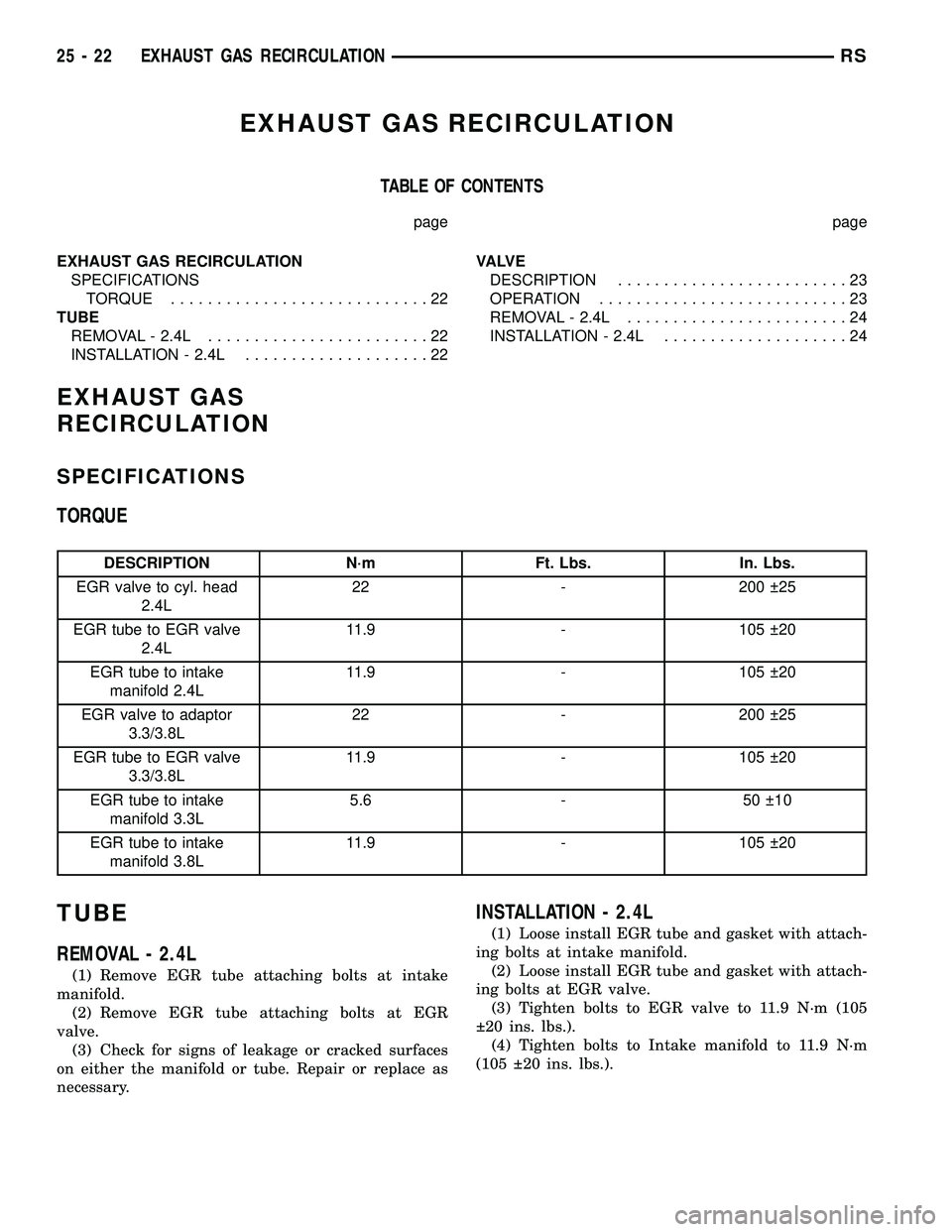
TORQUE
DESCRIPTION N´m Ft. Lbs. In. Lbs.
EGR valve to cyl. head
2.4L22 - 200 25
EGR tube to EGR valve
2.4L11.9 - 105 20
EGR tube to intake
manifold 2.4L11.9 - 105 20
EGR valve to adaptor
3.3/3.8L22 - 200 25
EGR tube to EGR valve
3.3/3.8L11.9 - 105 20
EGR tube to intake
manifold 3.3L5.6 - 50 10
EGR tube to intake
manifold 3.8L11.9 - 105 20
TUBE
REMOVAL - 2.4L
(1) Remove EGR tube attaching bolts at intake
manifold.
(2) Remove EGR tube attaching bolts at EGR
valve.
(3) Check for signs of leakage or cracked surfaces
on either the manifold or tube. Repair or replace as
necessary.
INSTALLATION - 2.4L
(1) Loose install EGR tube and gasket with attach-
ing bolts at intake manifold.
(2) Loose install EGR tube and gasket with attach-
ing bolts at EGR valve.
(3) Tighten bolts to EGR valve to 11.9 N´m (105
20 ins. lbs.).
(4) Tighten bolts to Intake manifold to 11.9 N´m
(105 20 ins. lbs.).
25 - 22 EXHAUST GAS RECIRCULATIONRS
Page 2298 of 2339
ON-BOARD DIAGNOSTICS
TABLE OF CONTENTS
page page
TASK MANAGER
DESCRIPTION.........................25OPERATION...........................25
TASK MANAGER
DESCRIPTION
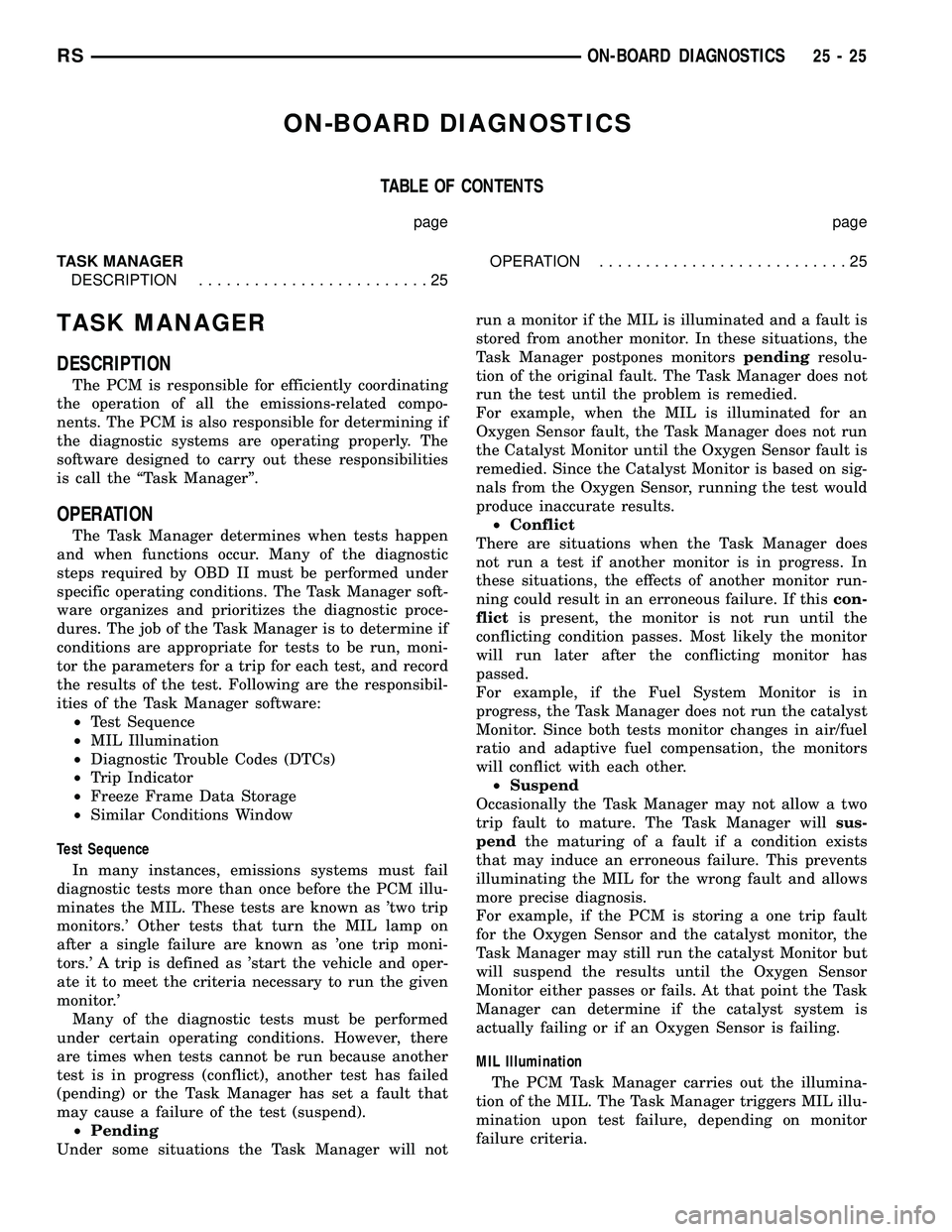
The PCM is responsible for efficiently coordinating
the operation of all the emissions-related compo-
nents. The PCM is also responsible for determining if
the diagnostic systems are operating properly. The
software designed to carry out these responsibilities
is call the ªTask Managerº.
OPERATION
The Task Manager determines when tests happen
and when functions occur. Many of the diagnostic
steps required by OBD II must be performed under
specific operating conditions. The Task Manager soft-
ware organizes and prioritizes the diagnostic proce-
dures. The job of the Task Manager is to determine if
conditions are appropriate for tests to be run, moni-
tor the parameters for a trip for each test, and record
the results of the test. Following are the responsibil-
ities of the Task Manager software:
²Test Sequence
²MIL Illumination
²Diagnostic Trouble Codes (DTCs)
²Trip Indicator
²Freeze Frame Data Storage
²Similar Conditions Window
Test Sequence
In many instances, emissions systems must fail
diagnostic tests more than once before the PCM illu-
minates the MIL. These tests are known as 'two trip
monitors.' Other tests that turn the MIL lamp on
after a single failure are known as 'one trip moni-
tors.' A trip is defined as 'start the vehicle and oper-
ate it to meet the criteria necessary to run the given
monitor.'
Many of the diagnostic tests must be performed
under certain operating conditions. However, there
are times when tests cannot be run because another
test is in progress (conflict), another test has failed
(pending) or the Task Manager has set a fault that
may cause a failure of the test (suspend).
²Pending
Under some situations the Task Manager will notrun a monitor if the MIL is illuminated and a fault is
stored from another monitor. In these situations, the
Task Manager postpones monitorspendingresolu-
tion of the original fault. The Task Manager does not
run the test until the problem is remedied.
For example, when the MIL is illuminated for an
Oxygen Sensor fault, the Task Manager does not run
the Catalyst Monitor until the Oxygen Sensor fault is
remedied. Since the Catalyst Monitor is based on sig-
nals from the Oxygen Sensor, running the test would
produce inaccurate results.
²Conflict
There are situations when the Task Manager does
not run a test if another monitor is in progress. In
these situations, the effects of another monitor run-
ning could result in an erroneous failure. If thiscon-
flictis present, the monitor is not run until the
conflicting condition passes. Most likely the monitor
will run later after the conflicting monitor has
passed.
For example, if the Fuel System Monitor is in
progress, the Task Manager does not run the catalyst
Monitor. Since both tests monitor changes in air/fuel
ratio and adaptive fuel compensation, the monitors
will conflict with each other.
²Suspend
Occasionally the Task Manager may not allow a two
trip fault to mature. The Task Manager willsus-
pendthe maturing of a fault if a condition exists
that may induce an erroneous failure. This prevents
illuminating the MIL for the wrong fault and allows
more precise diagnosis.
For example, if the PCM is storing a one trip fault
for the Oxygen Sensor and the catalyst monitor, the
Task Manager may still run the catalyst Monitor but
will suspend the results until the Oxygen Sensor
Monitor either passes or fails. At that point the Task
Manager can determine if the catalyst system is
actually failing or if an Oxygen Sensor is failing.
MIL Illumination
The PCM Task Manager carries out the illumina-
tion of the MIL. The Task Manager triggers MIL illu-
mination upon test failure, depending on monitor
failure criteria.
RSON-BOARD DIAGNOSTICS25-25
Page 2302 of 2339
INDEX
ABS FASTENER TORQUE,SPECIFICATIONS ...................... 5-91
ABSORBER - DESCRIPTION, SHOCK .......2-36
ABSORBER - INSTALLATION, SHOCK ......2-38
ABSORBER - OPERATION, SHOCK ........2-36
ABSORBER - REMOVAL, SHOCK ..........2-36
ABSORBER (UPPER BUSHING) - ASSEMBLY, SHOCK .................... 2-37
ABSORBER (UPPER BUSHING) - DISASSEMBLY, SHOCK .................2-37
A/C CLUTCH BREAK-IN, STANDARD PROCEDURE ........................ 24-15
A/C COMPRESSOR CLUTCH COIL, DIAGNOSIS AND TESTING .............24-14
A/C COMPRESSOR CLUTCH RELAY - DESCRIPTION ....................... 24-18
A/C COMPRESSOR CLUTCH RELAY - INSTALLATION ....................... 24-19
A/C COMPRESSOR CLUTCH RELAY - OPERATION ......................... 24-18
A/C COMPRESSOR CLUTCH RELAY - REMOVAL .......................... 24-19
A/C COMPRESSOR CLUTCH/COIL - DESCRIPTION ....................... 24-13
A/C COMPRESSOR CLUTCH/COIL - OPERATION ......................... 24-13
A/C COMPRESSOR, DESCRIPTION .......24-72
A/C COMPRESSOR, INSTALLATION .......24-74
A/C COMPRESSOR MOUNTING BRACKET, 2.4L ENGINE ...........24-74,24-75
A/C COMPRESSOR NOISE DIAGNOSIS, DIAGNOSIS AND TESTING .............24-72
A/C COMPRESSOR, OPERATION .........24-72
A/C COMPRESSOR, REMOVAL ..........24-73
A/C CONDENSER - DESCRIPTION ........24-75
A/C CONDENSER - OPERATION ..........24-75
A/C COOL DOWN TEST, DIAGNOSIS AND TESTING ............................ 24-6
A/C DISCHARGE LINE - INSTALLATION . . . 24-80
A/C DISCHARGE LINE - REMOVAL .......24-79
A/C EVAPORATOR - DESCRIPTION . . 24-80,24-98
A/C EVAPORATOR - INSTALLATION ......24-81
A/C EVAPORATOR - OPERATION ....24-80,24-98
A/C EVAPORATOR - REMOVAL ..........24-81
A/C EVAPORATOR, INSTALLATION - REAR ............................. 24-100
A/C EVAPORATOR LINE EXTENSION, INSTALLATION - REAR ...............24-100
A/C EVAPORATOR LINE EXTENSION, REMOVAL - REAR .................... 24-99
A/C EVAPORATOR, REMOVAL - REAR .....24-98
A/C EXPANSION VALVE - DESCRIPTION . . 24-100
A/C EXPANSION VALVE - OPERATION ....24-100
A/C EXPANSION VALVE, DIAGNOSIS AND TESTING - FRONT .................... 24-82
A/C EXPANSION VALVE, DIAGNOSIS AND TESTING - REAR .................... 24-101
A/C HEATER CONTROL - DESCRIPTION . . . 24-19
A/C PERFORMANCE TEST, DIAGNOSIS AND TESTING ........................ 24-7
A/C PRESSURE TRANSDUCER - DESCRIPTION ....................... 24-20
A/C PRESSURE TRANSDUCER - OPERATION ......................... 24-20
A/C PRESSURE TRANSDUCER, DIAGNOSIS AND TESTING .............24-21
A/C SYSTEM - CAUTION ...............24-66
A/C SYSTEM, SPECIFICATIONS ..........24-11
A/C SYSTEM, WARNING ...............24-66
ACCELERATOR PEDAL - INSTALLATION . . . 14-28
ACCELERATOR PEDAL - REMOVAL .......14-28
ACCESSORY DRIVE BELT - DIAGNOSIS AND TESTING .........................7-7
ACCESSORY DRIVE BELT TENSION, SPECIFICATIONS .......................7-5
ACCUMULATOR - DESCRIPTION . . . 21-218,21-73
ACCUMULATOR - OPERATION ....21-218,21-73
A/C-HEATER CONTROL - DESCRIPTION . . . 24-33
A/C-HEATER CONTROL - INSTALLATION . . . 24-34
A/C-HEATER CONTROL - OPERATION .....24-33
A/C-HEATER CONTROL - REMOVAL ......24-33
A/C-HEATER CONTROL CALIBRATION, STANDARD PROCEDURE ...............24-19
ACTUATOR - DESCRIPTION, BLEND DOOR ........................ 24-22,24-34
ACTUATOR - DESCRIPTION, ENGAGE ......8N-9
ACTUATOR - DESCRIPTION, LATCH ......8N-13 ACTUATOR - DESCRIPTION, MODE
DOOR ............................. 24-29
ACTUATOR - DESCRIPTION, RECIRCULATION DOOR ................24-31
ACTUATOR - INSTALLATION, BLEND DOOR ........................ 24-22,24-35
ACTUATOR - INSTALLATION, ENGAGE ....8N-10
ACTUATOR - INSTALLATION, INSIDE HANDLE ............................ 23-27
ACTUATOR - INSTALLATION, LATCH .....8N-14
ACTUATOR - INSTALLATION, MODE DOOR ............................. 24-30
ACTUATOR - INSTALLATION, RECIRCULATION DOOR ................24-32
ACTUATOR - OPERATION, BLEND DOOR . . 24-22, 24-35
ACTUATOR - OPERATION, ENGAGE .......8N-9
ACTUATOR - OPERATION, LATCH ........8N-13
ACTUATOR - OPERATION, MODE DOOR . . . 24-29
ACTUATOR - OPERATION, RECIRCULATION DOOR ................24-31
ACTUATOR - REAR - DESCRIPTION, MODE DOOR ........................ 24-39
ACTUATOR - REAR - INSTALLATION, MODE DOOR ........................ 24-40
ACTUATOR - REAR - OPERATION, MODE DOOR ............................. 24-39
ACTUATOR - REAR - REMOVAL, MODE DOOR ............................. 24-39
ACTUATOR - REMOVAL, BLEND DOOR . . . 24-22, 24-35
ACTUATOR - REMOVAL, ENGAGE ..........8N-9
ACTUATOR - REMOVAL, INSIDE HANDLE . . 23-27
ACTUATOR - REMOVAL, LATCH .........8N-13
ACTUATOR - REMOVAL, MODE DOOR ....24-29
ACTUATOR - REMOVAL, RECIRCULATION DOOR ............................. 24-32
ADAPTER - INSTALLATION, FRONT DISC BRAKE CALIPER ...................... 5-31
ADAPTER - INSTALLATION, OIL FILTER . . . 9-142
ADAPTER - REMOVAL, FRONT DISC BRAKE CALIPER ...................... 5-31
ADAPTER - REMOVAL, OIL FILTER .......9-142
ADAPTIVE MEMORIES, OPERATION - FUEL CORRECTION OR ................14-24
ADDING ADDITIONAL COOLANT - STANDARD PROCEDURE .................7-4
ADDITIONAL COOLANT - STANDARD PROCEDURE, ADDING ...................7-4
ADHESIVE ATTACHED - INSTALLATION, EXTERIOR NAME PLATES ..............23-51
ADHESIVE ATTACHED - REMOVAL, EXTERIOR NAME PLATES ..............23-51
ADHESIVE LOCATIONS - FOLD-IN-FLOOR ONLY - SPECIFICATIONS,
STRUCTURAL ...................... 23-228
ADHESIVE LOCATIONS - SPECIFICATIONS, STRUCTURAL ........23-218
ADJUSTABLE - INSTALLATION, PEDALS ....5-43
ADJUSTABLE - REMOVAL, PEDALS .......5-40
ADJUSTABLE PEDALS SWITCH - INSTALLATION ........................ 5-11
ADJUSTABLE PEDALS SWITCH - REMOVAL ........................... 5-11
ADJUSTE R-BOR C-PILLAR -
INSTALLATION, SEAT BELT HEIGHT ......8O-38
ADJUSTE R-BOR C-PILLAR -
REMOVAL, SEAT BELT HEIGHT ..........8O-38
ADJUSTER - DIAGNOSIS AND TESTING, DRUM BRAKE AUTOMATIC ..............5-14
ADJUSTER - INSTALLATION, FRONT SEAT TRACK MANUAL ...............23-126
ADJUSTER - INSTALLATION, FRONT SEAT TRACK POWER ................23-124
ADJUSTER - REMOVAL, FRONT SEAT TRACK MANUAL .................... 23-125
ADJUSTER - REMOVAL, FRONT SEAT TRACK POWER ..................... 23-124
ADJUSTER KNOB - INSTALLATION, SEAT BELT HEIGHT ....................... 8O-38
ADJUSTER KNOB - REMOVAL, SEAT BELT HEIGHT ....................... 8O-38
ADJUSTER NOISE DIAGNOSIS - DIAGNOSIS AND TESTING, HYDRAULIC
LASH ............................... 9-34
ADJUSTER TENSION RELEASE - STANDARD PROCEDURE, PARKING
BRAKE AUTOMATIC .................... 5-63ADJUSTER TENSION RESET -
STANDARD PROCEDURE, PARKING
BRAKE AUTOMATIC .................... 5-64
ADJUSTER/MANUAL - OCS - INSTALLATION, FRONT SEAT TRACK ....23-128
ADJUSTER/MANUAL - OCS - REMOVAL, FRONT SEAT TRACK .................23-126
ADJUSTER/POWER - OCS - INSTALLATION, FRONT SEAT TRACK ....23-125
ADJUSTER/POWER - OCS - REMOVAL, FRONT SEAT TRACK .................23-124
ADJUSTERS - INSTALLATION, HYDRAULIC LASH ..................... 9-35
ADJUSTERS - REMOVAL, HYDRAULIC LASH ............................... 9-35
AERATION - DIAGNOSIS AND TESTING, COOLING SYSTEM .....................7-4
AFTER AN AIRBAG DEPLOYMENT - STANDARD PROCEDURE, SERVICE .......8O-7
AIR CLEANER ELEMENT - INSTALLATION . 9-101, 9-24
AIR CLEANER ELEMENT - REMOVAL . 9-101,9-24
AIR CLEANER HOUSING - INSTALLATION . 9-102, 9-25
AIR CLEANER HOUSING - REMOVAL . 9-101,9-25
AIR CONDITIONER, DESCRIPTION - HEATER ............................. 24-1
AIR CONDITIONER, OPERATION - HEATER ............................. 24-4
AIR CONTROL MOTOR - DESCRIPTION, IDLE ............................... 14-33
AIR CONTROL MOTOR - INSTALLATION, IDLE ............................... 14-33
AIR CONTROL MOTOR - OPERATION, IDLE ............................... 14-33
AIR CONTROL MOTOR - REMOVAL, IDLE . . 14-33
AIR EXHAUSTER - DESCRIPTION, REAR QUARTER PANEL/FENDER ..............23-59
AIR EXHAUSTER - INSTALLATION, REAR QUARTER PANEL/FENDER ..............23-60
AIR EXHAUSTER - REMOVAL, REAR QUARTER PANEL/FENDER ..............23-59
AIR FILTER - DESCRIPTION ............24-42
AIR FILTER - INSTALLATION ............24-43
AIR FILTER - REMOVAL ...............24-42
AIR GAP, SPECIFICATIONS - WHEEL SPEED SENSOR ....................... 5-91
AIR INTAKE PIPE - INSTALLATION ......24-115
AIR INTAKE PIPE - REMOVAL ..........24-115
AIR OUTLETS - DESCRIPTION .....24-43,24-56
AIR OUTLETS - INSTALLATION ..........24-56
AIR OUTLETS - REMOVAL .............24-56
AIR PRESSURE TESTS - DIAGNOSIS AND TESTING, CLUTCH ...........21-153,21-8
AIR TEMPERATURE SENSOR - DESCRIPTION, INLET .................14-34
AIRBAG - DESCRIPTION, CURTAIN .......8O-12
AIRBAG - DESCRIPTION, DRIVER ........8O-16
AIRBAG - DESCRIPTION, KNEE BLOCKER . 8O-22
AIRBAG - DESCRIPTION, PASSENGER ....8O-30
AIRBAG - INSTALLATION, CURTAIN ......8O-16
AIRBAG - INSTALLATION, DRIVER .......8O-18
AIRBAG - INSTALLATION, KNEE BLOCKER .......................... 8O-23
AIRBAG - INSTALLATION, PASSENGER . . . 8O-32
AIRBAG - OPERATION, CURTAIN ........8O-13
AIRBAG - OPERATION, DRIVER .........8O-16
AIRBAG - OPERATION, KNEE BLOCKER . . . 8O-22
AIRBAG - OPERATION, PASSENGER ......8O-30
AIRBAG - REMOVAL, CURTAIN ..........8O-14
AIRBAG - REMOVAL, DRIVER ...........8O-17
AIRBAG - REMOVAL, KNEE BLOCKER ....8O-23
AIRBAG - REMOVAL, PASSENGER .......8O-30
AIRBAG DEPLOYMENT - STANDARD PROCEDURE, SERVICE AFTER AN ........8O-7
AIRBAG DISABLED INDICATOR - DESCRIPTION, PASSENGER ............8O-33
AIRBAG DISABLED INDICATOR - INSTALLATION, PASSENGER ...........8O-34
AIRBAG DISABLED INDICATOR - OPERATION, PASSENGER ..............8O-33
AIRBAG DISABLED INDICATOR - REMOVAL, PASSENGER ...............8O-34
AIRBAG SYSTEM - DIAGNOSIS AND TESTING ............................ 8O-6
AIRBAGS - STANDARD PROCEDURE, HANDLING .......................... 8O-6
RS INDEX1
Description Group-Page Description Group-Page Description Group-Page