2005 CHRYSLER VOYAGER Page 61
[x] Cancel search: Page 61Page 1386 of 2339
FUEL INJECTION
TABLE OF CONTENTS
page page
FUEL INJECTION
OPERATION
OPERATION - INJECTION SYSTEM.......22
OPERATION - MODES OF OPERATION....22
FUEL CORRECTION or ADAPTIVE
MEMORIES..........................24
PROGRAMMABLE COMMUNICATIONS
INTERFACE (PCI) BUS.................25
SYSTEM DIAGNOSIS..................26
SPECIFICATIONS
TORQUE............................26
SPECIAL TOOLS
FUEL...............................27
ACCELERATOR PEDAL
REMOVAL.............................28
INSTALLATION.........................28
CRANKSHAFT POSITION SENSOR
DESCRIPTION.........................29
OPERATION...........................29
REMOVAL.............................30
INSTALLATION - 2.4L....................30
ENGINE SPEED SENSOR
DESCRIPTION.........................30
OPERATION...........................30
FUEL INJECTOR
DESCRIPTION.........................30
OPERATION...........................31
REMOVAL
REMOVAL - 2.4L......................31
REMOVAL - 3.3/3.8L...................31
INSTALLATION
INSTALLATION - 2.4L..................32
INSTALLATION - 3.3/3.8L................32
FUEL PUMP RELAY
DESCRIPTION.........................32
OPERATION...........................32
IDLE AIR CONTROL MOTOR
DESCRIPTION.........................33
OPERATION...........................33REMOVAL.............................33
INSTALLATION.........................33
INLET AIR TEMPERATURE SENSOR
DESCRIPTION.........................34
MAP SENSOR
DESCRIPTION.........................34
OPERATION...........................34
REMOVAL
REMOVAL - 2.4L......................35
REMOVAL - 3.3/3.8L...................35
INSTALLATION
INSTALLATION - 2.4L..................36
INSTALLATION - 3.3/3.8L................36
O2 SENSOR
DESCRIPTION.........................36
OPERATION...........................36
REMOVAL
REMOVAL - UPSTREAM 1/1 - 2.4L........37
REMOVAL - UPSTREAM 1/1 - 3.3/3.8L.....38
REMOVAL - DOWNSTREAM 1/2 - 2.4/3.3/
3.8L................................38
INSTALLATION
INSTALLATION - UPSTREAM 1/1 - 2.4L.....38
INSTALLATION - UPSTREAM 1/1 - 3.3/3.8L . . 39
INSTALLATION DOWNSTREAM 2/1 -
2.4/3.3/3.8L..........................39
THROTTLE BODY
DESCRIPTION.........................39
OPERATION...........................39
REMOVAL.............................40
INSTALLATION.........................40
THROTTLE CONTROL CABLE
REMOVAL.............................40
INSTALLATION.........................40
THROTTLE POSITION SENSOR
DESCRIPTION.........................40
OPERATION...........................41
REMOVAL - 3.3/3.8L.....................41
INSTALLATION - 3.3/3.8L.................41
RSFUEL INJECTION14-21
Page 1408 of 2339
STEERING
TABLE OF CONTENTS
page page
STEERING
DESCRIPTION - POWER STEERING SYSTEM . . 1
OPERATION - POWER STEERING SYSTEM . . . 1
DIAGNOSIS AND TESTING
DIAGNOSIS AND TESTING - POWER
STEERING SYSTEM FLOW AND
PRESSURE TEST......................1
DIAGNOSIS AND TESTING - STEERING
SYSTEM DIAGNOSIS CHARTS............3SPECIFICATIONS
POWER STEERING FASTENER TORQUE . . . 9
SPECIAL TOOLS
POWER STEERING....................9
COLUMN..............................10
GEAR.................................26
PUMP.................................36
STEERING
DESCRIPTION - POWER STEERING SYSTEM
This vehicle comes with power steering as stan-
dard equipment. The power steering system consists
of these major components:
²POWER STEERING PUMP
²POWER STEERING GEAR
²POWER STEERING FLUID
²POWER STEERING FLUID COOLER (If
Equipped)
²POWER STEERING FLUID RESERVOIR
²POWER STEERING FLUID SUPPLY HOSE
²POWER STEERING FLUID PRESSURE HOSE
²POWER STEERING FLUID RETURN HOSE
For information on the first two components, refer
to their respective sections within this service man-
ual group. Information on all other components can
be found in POWER STEERING PUMP.
OPERATION - POWER STEERING SYSTEM
Turning of the steering wheel is converted into lin-
ear (side-to-side) travel through the meshing of the
helical pinion teeth with the rack teeth within the
steering gear. The lateral travel pushes and pulls the
tie rods to change the direction of the vehicle's front
wheels.
Power assist steering is provided by a belt driven
rotary type pump. It directs fluid through power
steering fluid hoses to the power steering gear where
it is used to assist the driver's turning effort.
Manual steering control of the vehicle can be main-
tained if power steering assist is lost. However,
under this condition, steering effort is significantly
increased.
DIAGNOSIS AND TESTING
DIAGNOSIS AND TESTING - POWER STEERING
SYSTEM FLOW AND PRESSURE TEST
ALL ENGINES
The following procedure is to be used to test the
operation of the power steering system on this vehi-
cle. This test will provide the flow rate of the power
steering pump along with the maximum relief pres-
sure. This test is to be performed to determine if the
power steering pump or power steering gear is not
functioning properly. The following flow and pressure
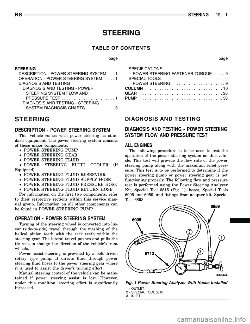
test is performed using the Power Steering Analyzer
Kit, Special Tool 6815 (Fig. 1), hoses, Special Tools
6905 and 6959, and fittings from adapter kit, Special
Tool 6893.
Fig. 1 Power Steering Analyzer With Hoses Installed
1 - OUTLET
2 - SPECIAL TOOL 6815
3 - INLET
RSSTEERING19-1
Page 1417 of 2339
COLUMN
TABLE OF CONTENTS
page page
COLUMN
DESCRIPTION - STEERING COLUMN.......10
WARNING
WARNINGS AND CAUTIONS.............10
DIAGNOSIS AND TESTING - STEERING
COLUMN............................11
REMOVAL.............................11
INSTALLATION.........................16
SPECIFICATIONS
COLUMN FASTENER TORQUE...........17
IGNITION SWITCH
REMOVAL.............................17
INSTALLATION.........................19
KEY/LOCK CYLINDER
DESCRIPTION.........................20OPERATION...........................20
REMOVAL.............................20
INSTALLATION.........................20
SHROUD - LOWER
REMOVAL.............................21
INSTALLATION.........................21
SHROUD - UPPER
REMOVAL.............................22
INSTALLATION.........................22
STEERING WHEEL
REMOVAL.............................23
INSTALLATION.........................24
COLUMN
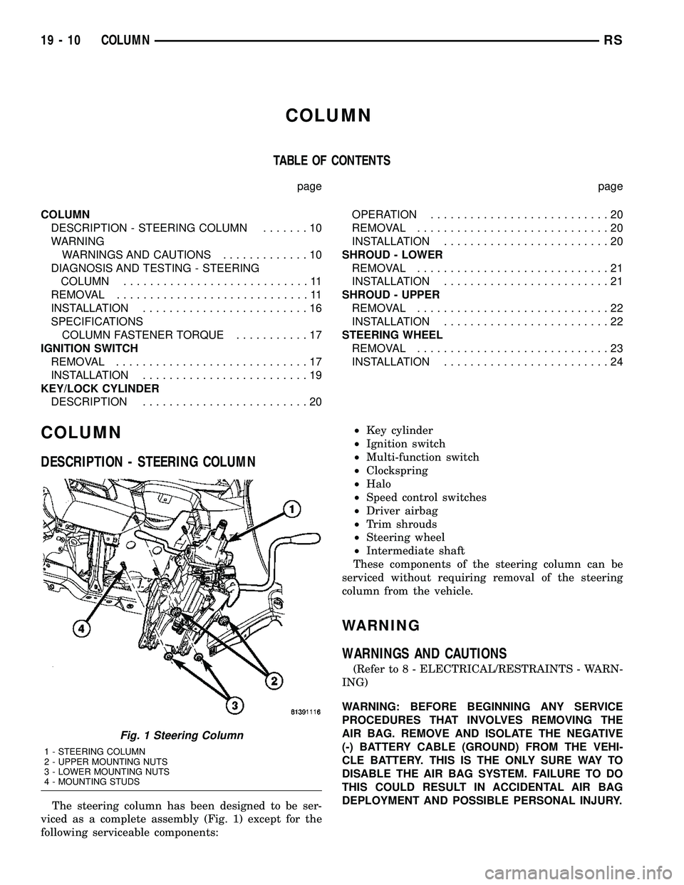
DESCRIPTION - STEERING COLUMN
The steering column has been designed to be ser-
viced as a complete assembly (Fig. 1) except for the
following serviceable components:²Key cylinder
²Ignition switch
²Multi-function switch
²Clockspring
²Halo
²Speed control switches
²Driver airbag
²Trim shrouds
²Steering wheel
²Intermediate shaft
These components of the steering column can be
serviced without requiring removal of the steering
column from the vehicle.
WARNING
WARNINGS AND CAUTIONS
(Refer to 8 - ELECTRICAL/RESTRAINTS - WARN-
ING)
WARNING: BEFORE BEGINNING ANY SERVICE
PROCEDURES THAT INVOLVES REMOVING THE
AIR BAG. REMOVE AND ISOLATE THE NEGATIVE
(-) BATTERY CABLE (GROUND) FROM THE VEHI-
CLE BATTERY. THIS IS THE ONLY SURE WAY TO
DISABLE THE AIR BAG SYSTEM. FAILURE TO DO
THIS COULD RESULT IN ACCIDENTAL AIR BAG
DEPLOYMENT AND POSSIBLE PERSONAL INJURY.
Fig. 1 Steering Column
1 - STEERING COLUMN
2 - UPPER MOUNTING NUTS
3 - LOWER MOUNTING NUTS
4 - MOUNTING STUDS
19 - 10 COLUMNRS
Page 1433 of 2339
GEAR
TABLE OF CONTENTS
page page
GEAR
DESCRIPTION.........................26
OPERATION...........................26
WARNING
WARNINGS AND CAUTIONS.............26
REMOVAL
REMOVAL - LHD GEAR.................26
REMOVAL - RHD GEAR................29INSTALLATION
INSTALLATION - LHD GEAR.............31
INSTALLATION - RHD GEAR.............33
SPECIAL TOOLS
POWER STEERING GEAR..............34
OUTER TIE ROD
REMOVAL.............................34
INSTALLATION.........................35
GEAR
DESCRIPTION
This vehicle is equipped with a rack and pinion
power steering gear (Fig. 1). It is mounted to the
underside of the front suspension cradle/crossmem-
ber.
The steering column is attached to the gear
through the use of an intermediate shaft and cou-
plers. The outer ends of the power steering gear's
outer tie rods connect to the steering knuckles.
NOTE: The power steering gear should NOT be ser-
viced or adjusted unless DaimlerChrysler Corpora-
tion authorizes. If a malfunction or oil leak occurs,
the complete steering gear should be replaced.
Only the outer tie rods may be replaced separately
from the rest of the gear.
OPERATION
Turning of the steering wheel is converted into lin-
ear (side-to-side) travel through the meshing of the
helical pinion teeth with the rack teeth in the steer-
ing gear. This travel pushes and pulls the tie rods to
change the direction of the vehicle's front wheels.
Power assist steering provided by the power steer-
ing pump is controlled by an open center, rotary type
control valve which directs oil from the pump to
either side of the integral rack piston upon demand.
Road feel is controlled by the diameter of a torsion
bar which initially steers the vehicle. As required
steering effort increases, as in a turn, the torsion bar
twists, causing relative rotary motion between the
rotary valve body and the valve spool. This move-
ment directs oil behind the integral rack piston
which, in turn, builds hydraulic pressure and assists
in the turning effort.Manual steering control of the vehicle can be main-
tained if power steering assist is lost. However,
under this condition, steering effort is significantly
increased.
WARNING
WARNINGS AND CAUTIONS
WARNING: POWER STEERING FLUID, ENGINE
PARTS AND EXHAUST SYSTEM MAY BE
EXTREMELY HOT IF ENGINE HAS BEEN RUNNING.
DO NOT START ENGINE WITH ANY LOOSE OR DIS-
CONNECTED HOSES. DO NOT ALLOW HOSES TO
TOUCH HOT EXHAUST MANIFOLD OR CATALYST.
WARNING: FLUID LEVEL SHOULD BE CHECKED
WITH THE ENGINE OFF TO PREVENT PERSONAL
INJURY FROM MOVING PARTS.
CAUTION: When the system is open, cap all open
ends of the hoses, power steering pump fittings or
power steering gear ports to prevent entry of for-
eign material into the components.
REMOVAL
REMOVAL - LHD GEAR
(1) Remove cap from power steering fluid reser-
voir.
(2) Using a siphon pump, remove as much fluid as
possible from the power steering fluid reservoir.Use
care not to damage the filter mesh below the
fluid surface.
19 - 26 GEARRS
Page 1443 of 2339
PUMP
TABLE OF CONTENTS
page page
PUMP
DESCRIPTION
DESCRIPTION - PUMP (2.4L/3.3L/3.8L
ENGINE)............................36
DESCRIPTION - PUMP (DIESEL).........37
OPERATION...........................37
WARNING.............................37
CAUTION.............................37
STANDARD PROCEDURE - POWER
STEERING PUMP INITIAL OPERATION.....37
REMOVAL
REMOVAL - PUMP (2.4L ENGINE).........38
REMOVAL - PUMP (3.3L/3.8L ENGINE).....40
REMOVAL - PUMP (DIESEL).............41
DISASSEMBLY - PUMP (PULLEY)..........41
ASSEMBLY - PUMP (PULLEY).............42
INSTALLATION
INSTALLATION - PUMP (2.4L ENGINE).....43
INSTALLATION - PUMP (3.3L/3.8L ENGINE) . 43
INSTALLATION - PUMP (DIESEL).........43
SPECIAL TOOLS
POWER STEERING PUMP..............44
FLUID
STANDARD PROCEDURE - POWER
STEERING FLUID LEVEL CHECKING......44
FLUID COOLER
DESCRIPTION.........................45
OPERATION...........................45
REMOVAL.............................45
INSTALLATION.........................45
HOSE - POWER STEERING PRESSURE
REMOVAL
REMOVAL - 2.4L ENGINE...............46REMOVAL - 3.3L/3.8L ENGINE...........46
INSTALLATION
INSTALLATION - 2.4L ENGINE...........47
INSTALLATION - 3.3L/3.8L ENGINE........48
HOSE - POWER STEERING RETURN
REMOVAL
REMOVAL - 2.4L ENGINE...............49
REMOVAL - 3.3L/3.8L ENGINE...........49
INSTALLATION
INSTALLATION - 2.4L ENGINE...........50
INSTALLATION - 3.3L/3.8L ENGINE........50
HOSE - POWER STEERING SUPPLY
REMOVAL
REMOVAL - 2.4L ENGINE...............51
REMOVAL - 3.3L/3.8L ENGINE...........51
INSTALLATION
INSTALLATION - 2.4L ENGINE...........51
INSTALLATION - 3.3L/3.8L ENGINE........52
RESERVOIR - POWER STEERING FLUID
DESCRIPTION
DESCRIPTION - 2.4L/3.3L/3.8L ENGINE....52
DESCRIPTION - DIESEL................52
OPERATION...........................52
REMOVAL
REMOVAL - 2.4L ENGINE...............52
REMOVAL - 3.3L/3.8L ENGINE...........52
REMOVAL - DIESEL...................52
INSTALLATION
INSTALLATION - 2.4L ENGINE...........53
INSTALLATION - 3.3L/3.8L ENGINE........53
INSTALLATION - DIESEL................53
PUMP
DESCRIPTION
DESCRIPTION - PUMP (2.4L/3.3L/3.8L
ENGINE)
Hydraulic pressure for the operation of the power
steering gear is provided by a belt driven power
steering pump. The power steering pump is mounted
on the back side of the engine on all engine applica-
tions. The pumps are different depending on the
engine option. The pump for the 2.4L engine is madeout of cast iron and steel (Fig. 1). The pump used on
the 3.3L/3.8L engine is made of aluminum (Fig. 2).
The pump for the 3.3L/3.8L engine does not have a
return fitting as the pump for the 2.4L engine does.
The power steering return hose on the 3.3L/3.8L
engine goes to the reservoir instead of the pump.
19 - 36 PUMPRS
Page 1462 of 2339
TRANSMISSION/TRANSAXLE
TABLE OF CONTENTS
page page
40TE AUTOMATIC TRANSAXLE..............141TE AUTOMATIC TRANSAXLE............146
40TE AUTOMATIC TRANSAXLE
TABLE OF CONTENTS
page page
40TE AUTOMATIC TRANSAXLE
DESCRIPTION..........................2
OPERATION............................4
DIAGNOSIS AND TESTING
DIAGNOSIS AND TESTING - 4XTE
TRANSAXLE GENERAL DIAGNOSIS........5
DIAGNOSIS AND TESTING - ROAD TEST....5
DIAGNOSIS AND TESTING - HYDRAULIC
PRESSURE TESTS.....................6
DIAGNOSIS AND TESTING - CLUTCH AIR
PRESSURE TESTS.....................8
DIAGNOSIS AND TESTING - TORQUE
CONVERTER HOUSING FLUID LEAKAGE....9
REMOVAL.............................9
DISASSEMBLY.........................12
ASSEMBLY............................29
INSTALLATION.........................51
SCHEMATICS AND DIAGRAMS
4XTE TRANSAXLE HYDRAULIC
SCHEMATICS........................54
SPECIFICATIONS - 41TE TRANSAXLE.......66
SPECIAL TOOLS.......................68
ACCUMULATOR
DESCRIPTION.........................73
OPERATION...........................73
DRIVING CLUTCHES
DESCRIPTION.........................74
OPERATION...........................74
FINAL DRIVE
DESCRIPTION.........................74
OPERATION...........................75
DISASSEMBLY.........................75
ASSEMBLY............................78
ADJUSTMENTS
DIFFERENTIAL BEARING PRELOAD
MEASUREMENT AND ADJUSTMENT......79FLUID
STANDARD PROCEDURE
FLUID LEVEL AND CONDITION CHECK....82
STANDARD PROCEDURE - FLUID AND
FILTER SERVICE......................82
GEAR SHIFT CABLE
REMOVAL.............................84
HOLDING CLUTCHES
DESCRIPTION.........................86
OPERATION...........................86
INPUT CLUTCH ASSEMBLY
DISASSEMBLY.........................86
ASSEMBLY............................95
OIL PUMP
DESCRIPTION........................110
OPERATION..........................110
DISASSEMBLY........................110
ASSEMBLY...........................112
PLANETARY GEARTRAIN
DESCRIPTION........................112
OPERATION..........................112
SEAL - OIL PUMP
REMOVAL............................113
INSTALLATION........................113
SHIFT INTERLOCK SOLENOID
DESCRIPTION........................113
OPERATION..........................114
DIAGNOSIS AND TESTING - BRAKE/
TRANSMISSION SHIFT INTERLOCK
SOLENOID..........................115
REMOVAL............................115
INSTALLATION........................116
SOLENOID/PRESSURE SWITCH ASSY
DESCRIPTION........................117
OPERATION..........................118
REMOVAL............................118
INSTALLATION........................119
RSTRANSMISSION/TRANSAXLE21-1
Page 1581 of 2339
SPEED SENSOR - INPUT
DESCRIPTION
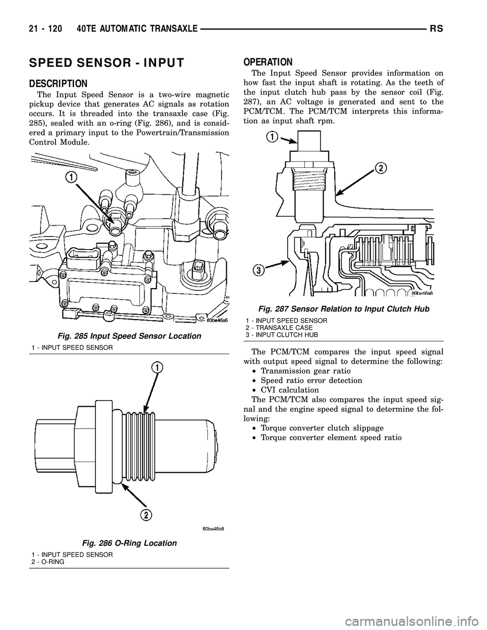
The Input Speed Sensor is a two-wire magnetic
pickup device that generates AC signals as rotation
occurs. It is threaded into the transaxle case (Fig.
285), sealed with an o-ring (Fig. 286), and is consid-
ered a primary input to the Powertrain/Transmission
Control Module.
OPERATION
The Input Speed Sensor provides information on
how fast the input shaft is rotating. As the teeth of
the input clutch hub pass by the sensor coil (Fig.
287), an AC voltage is generated and sent to the
PCM/TCM. The PCM/TCM interprets this informa-
tion as input shaft rpm.
The PCM/TCM compares the input speed signal
with output speed signal to determine the following:
²Transmission gear ratio
²Speed ratio error detection
²CVI calculation
The PCM/TCM also compares the input speed sig-
nal and the engine speed signal to determine the fol-
lowing:
²Torque converter clutch slippage
²Torque converter element speed ratio
Fig. 285 Input Speed Sensor Location
1 - INPUT SPEED SENSOR
Fig. 286 O-Ring Location
1 - INPUT SPEED SENSOR
2 - O-RING
Fig. 287 Sensor Relation to Input Clutch Hub
1 - INPUT SPEED SENSOR
2 - TRANSAXLE CASE
3 - INPUT CLUTCH HUB
21 - 120 40TE AUTOMATIC TRANSAXLERS
Page 1588 of 2339
STATOR
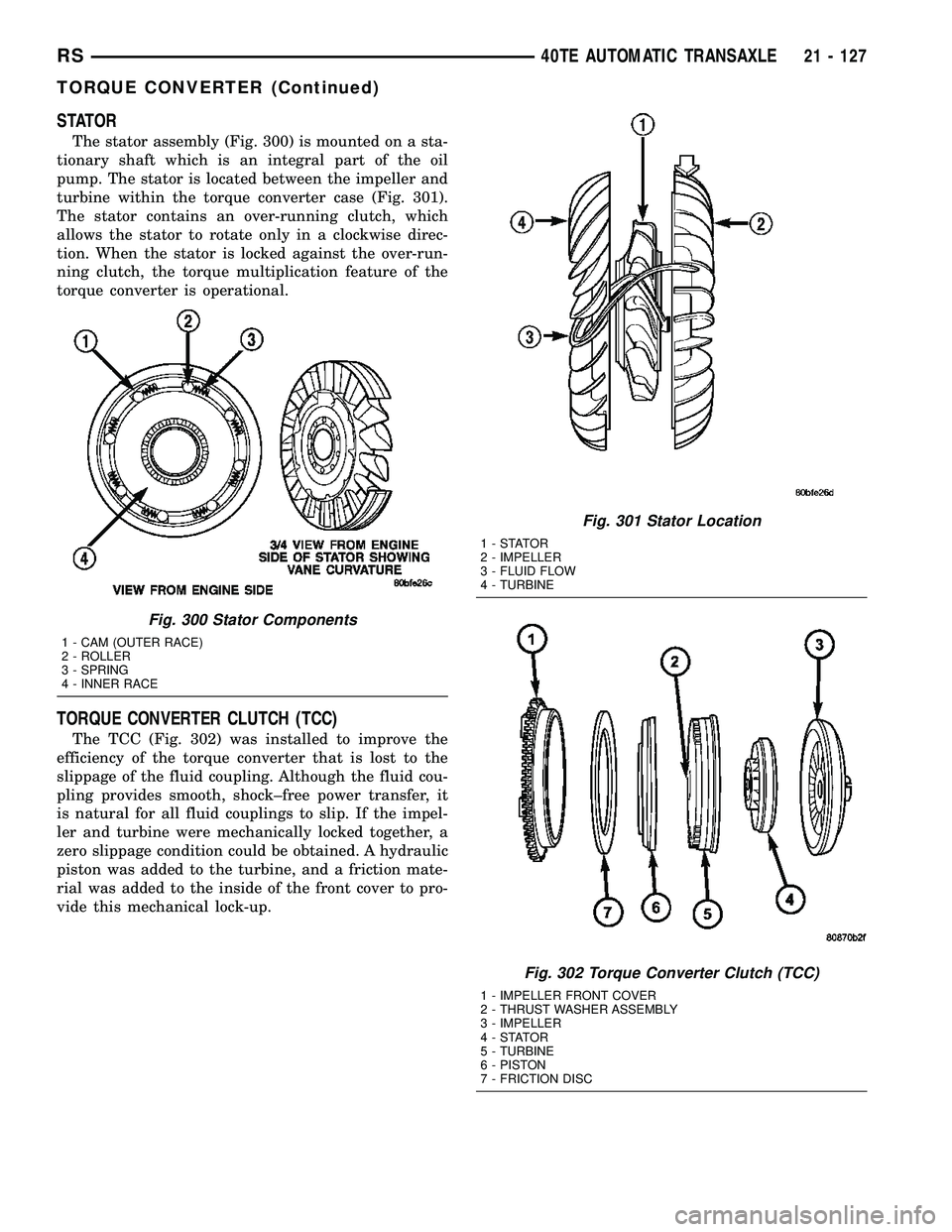
The stator assembly (Fig. 300) is mounted on a sta-
tionary shaft which is an integral part of the oil
pump. The stator is located between the impeller and
turbine within the torque converter case (Fig. 301).
The stator contains an over-running clutch, which
allows the stator to rotate only in a clockwise direc-
tion. When the stator is locked against the over-run-
ning clutch, the torque multiplication feature of the
torque converter is operational.
TORQUE CONVERTER CLUTCH (TCC)
The TCC (Fig. 302) was installed to improve the
efficiency of the torque converter that is lost to the
slippage of the fluid coupling. Although the fluid cou-
pling provides smooth, shock±free power transfer, it
is natural for all fluid couplings to slip. If the impel-
ler and turbine were mechanically locked together, a
zero slippage condition could be obtained. A hydraulic
piston was added to the turbine, and a friction mate-
rial was added to the inside of the front cover to pro-
vide this mechanical lock-up.
Fig. 300 Stator Components
1 - CAM (OUTER RACE)
2 - ROLLER
3 - SPRING
4 - INNER RACE
Fig. 301 Stator Location
1-STATOR
2 - IMPELLER
3 - FLUID FLOW
4 - TURBINE
Fig. 302 Torque Converter Clutch (TCC)
1 - IMPELLER FRONT COVER
2 - THRUST WASHER ASSEMBLY
3 - IMPELLER
4-STATOR
5 - TURBINE
6 - PISTON
7 - FRICTION DISC
RS40TE AUTOMATIC TRANSAXLE21 - 127
TORQUE CONVERTER (Continued)