2005 CHRYSLER VOYAGER Page 61
[x] Cancel search: Page 61Page 1607 of 2339
41TE AUTOMATIC TRANSAXLE
TABLE OF CONTENTS
page page
41TE AUTOMATIC TRANSAXLE
DESCRIPTION........................147
OPERATION..........................149
DIAGNOSIS AND TESTING
DIAGNOSIS AND TESTING - 4XTE
TRANSAXLE GENERAL DIAGNOSIS......149
DIAGNOSIS AND TESTING - ROAD TEST . . 150
DIAGNOSIS AND TESTING - HYDRAULIC
PRESSURE TESTS...................150
DIAGNOSIS AND TESTING - CLUTCH AIR
PRESSURE TESTS...................153
DIAGNOSIS AND TESTING - TORQUE
CONVERTER HOUSING FLUID LEAKAGE . . 154
REMOVAL............................154
DISASSEMBLY........................157
ASSEMBLY...........................174
INSTALLATION........................196
SCHEMATICS AND DIAGRAMS
4XTE TRANSAXLE HYDRAULIC
SCHEMATICS.......................199
SPECIFICATIONS - 41TE TRANSAXLE......211
SPECIAL TOOLS
41TE AUTOMATIC TRANSAXLE.........213
ACCUMULATOR
DESCRIPTION........................218
OPERATION..........................218
DRIVING CLUTCHES
DESCRIPTION........................219
OPERATION..........................219
FINAL DRIVE
DESCRIPTION........................219
OPERATION..........................220
DISASSEMBLY........................220
ASSEMBLY...........................224
ADJUSTMENTS
ADJUSTMENT - DIFFERENTIAL BEARING
PRELOAD..........................228
FLUID
STANDARD PROCEDURE
FLUID LEVEL AND CONDITION CHECK . . . 230
STANDARD PROCEDURE - FLUID AND
FILTER SERVICE.....................231
GEAR SHIFT CABLE
REMOVAL............................233
INSTALLATION........................234
ADJUSTMENTS
GEARSHIFT CABLE ADJUSTMENT.......235
HOLDING CLUTCHES
DESCRIPTION........................236
OPERATION..........................236INPUT CLUTCH ASSEMBLY
DISASSEMBLY........................237
ASSEMBLY...........................246
OIL PUMP
DESCRIPTION........................261
OPERATION..........................261
DISASSEMBLY........................261
ASSEMBLY...........................263
PLANETARY GEARTRAIN
DESCRIPTION........................263
OPERATION..........................263
SEAL - OIL PUMP
REMOVAL............................264
INSTALLATION........................264
SHIFT INTERLOCK SOLENOID
DESCRIPTION........................264
OPERATION..........................265
DIAGNOSIS AND TESTING - BRAKE/
TRANSMISSION SHIFT INTERLOCK
SOLENOID..........................266
REMOVAL............................266
INSTALLATION........................267
SOLENOID/PRESSURE SWITCH ASSY
DESCRIPTION........................268
OPERATION..........................268
REMOVAL............................269
INSTALLATION........................270
SPEED SENSOR - INPUT
DESCRIPTION........................271
OPERATION..........................271
REMOVAL............................272
INSTALLATION........................272
SPEED SENSOR - OUTPUT
DESCRIPTION........................273
OPERATION..........................273
REMOVAL............................274
INSTALLATION........................274
TORQUE CONVERTER
DESCRIPTION........................275
OPERATION..........................278
REMOVAL............................280
INSTALLATION........................280
TRANSMISSION CONTROL RELAY
DESCRIPTION........................281
OPERATION..........................281
TRANSMISSION RANGE SENSOR
DESCRIPTION........................281
OPERATION..........................282
REMOVAL............................282
INSTALLATION........................282
21 - 146 41TE AUTOMATIC TRANSAXLERS
Page 1732 of 2339
SPEED SENSOR - INPUT
DESCRIPTION
The Input Speed Sensor is a two-wire magnetic
pickup device that generates AC signals as rotation
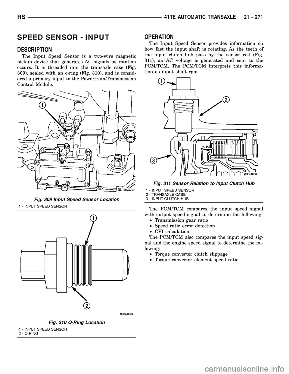
occurs. It is threaded into the transaxle case (Fig.
309), sealed with an o-ring (Fig. 310), and is consid-
ered a primary input to the Powertrain/Transmission
Control Module.
OPERATION
The Input Speed Sensor provides information on
how fast the input shaft is rotating. As the teeth of
the input clutch hub pass by the sensor coil (Fig.
311), an AC voltage is generated and sent to the
PCM/TCM. The PCM/TCM interprets this informa-
tion as input shaft rpm.
The PCM/TCM compares the input speed signal
with output speed signal to determine the following:
²Transmission gear ratio
²Speed ratio error detection
²CVI calculation
The PCM/TCM also compares the input speed sig-
nal and the engine speed signal to determine the fol-
lowing:
²Torque converter clutch slippage
²Torque converter element speed ratio
Fig. 309 Input Speed Sensor Location
1 - INPUT SPEED SENSOR
Fig. 310 O-Ring Location
1 - INPUT SPEED SENSOR
2 - O-RING
Fig. 311 Sensor Relation to Input Clutch Hub
1 - INPUT SPEED SENSOR
2 - TRANSAXLE CASE
3 - INPUT CLUTCH HUB
RS41TE AUTOMATIC TRANSAXLE21 - 271
Page 1739 of 2339
STATOR
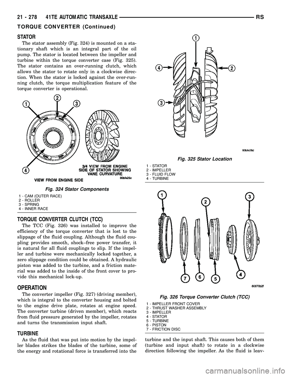
The stator assembly (Fig. 324) is mounted on a sta-
tionary shaft which is an integral part of the oil
pump. The stator is located between the impeller and
turbine within the torque converter case (Fig. 325).
The stator contains an over-running clutch, which
allows the stator to rotate only in a clockwise direc-
tion. When the stator is locked against the over-run-
ning clutch, the torque multiplication feature of the
torque converter is operational.
TORQUE CONVERTER CLUTCH (TCC)
The TCC (Fig. 326) was installed to improve the
efficiency of the torque converter that is lost to the
slippage of the fluid coupling. Although the fluid cou-
pling provides smooth, shock±free power transfer, it
is natural for all fluid couplings to slip. If the impel-
ler and turbine were mechanically locked together, a
zero slippage condition could be obtained. A hydraulic
piston was added to the turbine, and a friction mate-
rial was added to the inside of the front cover to pro-
vide this mechanical lock-up.
OPERATION
The converter impeller (Fig. 327) (driving member),
which is integral to the converter housing and bolted
to the engine drive plate, rotates at engine speed.
The converter turbine (driven member), which reacts
from fluid pressure generated by the impeller, rotates
and turns the transmission input shaft.
TURBINE
As the fluid that was put into motion by the impel-
ler blades strikes the blades of the turbine, some of
the energy and rotational force is transferred into theturbine and the input shaft. This causes both of them
(turbine and input shaft) to rotate in a clockwise
direction following the impeller. As the fluid is leav-
Fig. 324 Stator Components
1 - CAM (OUTER RACE)
2 - ROLLER
3 - SPRING
4 - INNER RACE
Fig. 325 Stator Location
1-STATOR
2 - IMPELLER
3 - FLUID FLOW
4 - TURBINE
Fig. 326 Torque Converter Clutch (TCC)
1 - IMPELLER FRONT COVER
2 - THRUST WASHER ASSEMBLY
3 - IMPELLER
4-STATOR
5 - TURBINE
6 - PISTON
7 - FRICTION DISC
21 - 278 41TE AUTOMATIC TRANSAXLERS
TORQUE CONVERTER (Continued)
Page 1758 of 2339
TIRES/WHEELS
TABLE OF CONTENTS
page page
TIRES/WHEELS
DIAGNOSIS AND TESTING - TIRE AND
WHEEL VIBRATION.....................1
STANDARD PROCEDURE
STANDARD PROCEDURE - TIRE AND
WHEEL BALANCE......................5
STANDARD PROCEDURE - TIRE AND
WHEEL MATCH MOUNTING..............7
STANDARD PROCEDURE - TIRE AND
WHEEL ROTATION.....................7
REMOVAL
REMOVAL - TIRE AND WHEEL ASSEMBLY
(ALUMINUM WHEEL)....................8
REMOVAL - TIRE AND WHEEL ASSEMBLY
(STEEL WHEEL).......................8
INSTALLATION
INSTALLATION - TIRE AND WHEEL
ASSEMBLY (ALUMINUM WHEEL)..........8
INSTALLATION - TIRE AND WHEEL
ASSEMBLY (STEEL WHEEL)..............8
TIRE PRESSURE MONITORING
DESCRIPTION..........................9
OPERATION...........................10
SENSOR - TPM
DESCRIPTION.........................10
OPERATION...........................10
CAUTION.............................11
DIAGNOSIS AND TESTING - TIRE PRESSURE
SENSOR............................11
REMOVAL.............................11
INSTALLATION.........................11
TIRES
DESCRIPTION
DESCRIPTION - TIRE..................13
DESCRIPTION - RADIAL-PLY TIRES.......13
DESCRIPTION - REPLACEMENT TIRES....14
DESCRIPTION - SPARE TIRE
(TEMPORARY).......................14DIAGNOSIS AND TESTING
DIAGNOSIS AND TESTING - TIRE NOISE . . . 14
DIAGNOSIS AND TESTING - TIRE/VEHICLE
LEAD...............................14
DIAGNOSIS AND TESTING - TIRE WEAR
PATTERNS..........................16
DIAGNOSIS AND TESTING - TREAD WEAR
INDICATORS.........................16
STANDARD PROCEDURE
STANDARD PROCEDURE - TIRE INFLATION
PRESSURES.........................16
STANDARD PROCEDURE - TIRE
PRESSURE FOR HIGH SPEED
OPERATION.........................17
STANDARD PROCEDURE - TIRE LEAK
REPAIRING..........................17
CLEANING - TIRES.....................18
WHEELS
DESCRIPTION - WHEEL..................18
DIAGNOSIS AND TESTING - WHEEL
INSPECTION.........................19
CLEANING
WHEEL AND WHEEL TRIM CARE.........19
SPECIFICATIONS
WHEEL.............................19
WHEEL COVER
DESCRIPTION.........................19
REMOVAL.............................19
INSTALLATION.........................20
WHEEL MOUNTING STUDS - FRONT
REMOVAL.............................21
INSTALLATION.........................21
WHEEL MOUNTING STUDS - REAR
REMOVAL.............................22
INSTALLATION.........................22
TIRES/WHEELS
DIAGNOSIS AND TESTING - TIRE AND WHEEL
VIBRATION
Tire and wheel imbalance, runout and force varia-
tion can cause vehicles to exhibit steering wheel
vibration.
VISUAL INSPECTION
Visual inspection of the vehicle is recommended
prior to road testing or performing any other proce-
dure. Raise vehicle on a suitable hoist. (Refer to
LUBRICATION & MAINTENANCE/HOISTING -
STANDARD PROCEDURE)
Inspect for the following:
²Verify correct (OEM) wheel and tire, as well as
correct wheel weights. Aluminum wheels require
RSTIRES/WHEELS22-1
Page 1780 of 2339
BODY
TABLE OF CONTENTS
page page
BODY
DESCRIPTION - VEHICLE IDENTIFICATION....1
WARNING
SAFETY PRECAUTIONS AND WARNINGS . . . 1
DIAGNOSIS AND TESTING
WATER LEAKS........................1
WIND NOISE..........................2
STANDARD PROCEDURE
STANDARD PROCEDURE - PLASTIC BODY
PANEL REPAIR........................3
STANDARD PROCEDURE - HEAT STAKING . . 9
SPECIFICATIONS
TORQUE............................10
BODY LUBRICATION...................12
SPECIAL TOOLS
BODY..............................13DOOR - FRONT.........................14
DOORS - SLIDING.......................24
DECKLID/HATCH/LIFTGATE/TAILGATE.......40
EXTERIOR.............................45
HOOD.................................62
INSTRUMENT PANEL.....................65
INTERIOR..............................78
PAINT................................100
SEATS...............................102
STATIONARY GLASS....................161
WEATHERSTRIP/SEALS..................166
SUNROOF.............................169
BODY STRUCTURE.....................177
BODY
DESCRIPTION - VEHICLE IDENTIFICATION
Throughout this group, references to the
DaimlerChrysler Corporation vehicle family identifi-
cation code are used when describing a procedure
that is unique to that vehicle. Refer to Introduction
Group of this manual for detailed information on
vehicle identification. If a procedure is common to all
vehicles covered in this manual, no reference will be
made to a vehicle family code.
WARNING
SAFETY PRECAUTIONS AND WARNINGS
WARNING: USE A OSHA APPROVED BREATHING
FILTER WHEN SPRAYING PAINT OR SOLVENTS IN
A CONFINED AREA. PERSONAL INJURY CAN
RESULT.
AVOID PROLONGED SKIN CONTACT WITH PETRO-
LEUM OR ALCOHOL ± BASED CLEANING SOL-
VENTS. PERSONAL INJURY CAN RESULT.
DO NOT STAND UNDER A HOISTED VEHICLE THAT
IS NOT PROPERLY SUPPORTED ON SAFETY
STANDS. PERSONAL INJURY CAN RESULT.
CAUTION: When holes must be drilled or punched
in an inner body panel, verify depth of space to the
outer body panel, electrical wiring, or other compo-nents. Damage to vehicle can result.
Do not weld exterior panels unless combustible
material on the interior of vehicle is removed from
the repair area. Fire or hazardous conditions, can
result.
Always have a fire extinguisher ready for use when
welding.
Disconnect the negative (-) cable clamp from the
battery when servicing electrical components that
are live when the ignition is OFF. Damage to electri-
cal system can result.
Do not use abrasive chemicals or compounds on
painted surfaces. Damage to finish can result.
Do not use harsh alkaline based cleaning solvents
on painted or upholstered surfaces. Damage to fin-
ish or color can result.
Do not hammer or pound on plastic trim panel
when servicing interior trim. Plastic panels can
break.
DIAGNOSIS AND TESTING
WATER LEAKS
Water leaks can be caused by poor sealing,
improper body component alignment, body seam
porosity, missing plugs, or blocked drain holes. Cen-
trifugal and gravitational force can cause water to
drip from a location away from the actual leak point,
making leak detection difficult. All body sealing
points should be water tight in normal wet-driving
conditions. Water flowing downward from the front of
RSBODY23-1
Page 1793 of 2339
DOOR - FRONT
TABLE OF CONTENTS
page page
APPLIQUE
REMOVAL.............................14
INSTALLATION.........................14
CHECK STRAP
REMOVAL.............................15
INSTALLATION.........................15
DOOR
REMOVAL.............................15
INSTALLATION.........................15
DOOR GLASS
REMOVAL.............................16
INSTALLATION.........................17
FRAME CLOSEOUT MOLDING
REMOVAL ± A-PILLAR-HEADER, OR B-PILLAR . 17
INSTALLATION ± A-PILLAR-HEADER, OR
B-PILLAR............................17
HINGE
REMOVAL.............................17
INSTALLATION.........................18
LATCH
REMOVAL.............................18
INSTALLATION.........................18
LATCH STRIKER
REMOVAL.............................19INSTALLATION.........................19
LOCK CYLINDER
REMOVAL.............................19
INSTALLATION.........................19
TRIM PANEL
REMOVAL.............................20
INSTALLATION.........................20
WATERSHIELD
REMOVAL.............................21
INSTALLATION.........................21
WINDOW CRANK
REMOVAL.............................21
INSTALLATION.........................21
EXTERIOR HANDLE
REMOVAL.............................21
INSTALLATION.........................22
WINDOW REGULATOR - POWER
REMOVAL.............................22
INSTALLATION.........................22
WINDOW REGULATOR - MANUAL
REMOVAL.............................22
INSTALLATION.........................23
APPLIQUE
REMOVAL
(1) Roll door glass down.
(2) Remove outer door belt molding.
(3) Disengage clips holding front edge of applique
to door frame.
(4) Remove applique from vehicle (Fig. 1).
INSTALLATION
(1) Position applique on vehicle.
(2) Hook rear edge of applique over rear edge of
door frame and seat applique bottom edge on sheet
metal.
(3) Engage clips to hold front edge of applique to
door frame.
(4) Install outer door belt molding.
23 - 14 DOOR - FRONTRS
Page 1803 of 2339

DOORS - SLIDING
TABLE OF CONTENTS
page page
CENTER HINGE
REMOVAL.............................24
INSTALLATION.........................24
SLIDING DOOR STOP BUMPER BEZEL
REMOVAL.............................25
INSTALLATION.........................25
STOP BUMPER
REMOVAL.............................25
INSTALLATION.........................25
HOLD OPEN LATCH
REMOVAL.............................25
INSTALLATION.........................25
HOLD OPEN LATCH STRIKER
REMOVAL.............................26
INSTALLATION.........................26
LATCH / LOCK ASSEMBLY
REMOVAL.............................26
INSTALLATION.........................27
INSIDE HANDLE ACTUATOR
REMOVAL.............................27
INSTALLATION.........................27
CENTER STRIKER
REMOVAL.............................28
INSTALLATION.........................28
LOWER HINGE
REMOVAL.............................28
INSTALLATION.........................28
REAR LATCH STRIKER
REMOVAL.............................29
INSTALLATION.........................29
SLIDING DOOR
REMOVAL.............................29
INSTALLATION.........................29ADJUSTMENTS
SLIDING DOOR ADJUSTMENTS..........30
STABILIZER
REMOVAL.............................33
INSTALLATION.........................33
STABILIZER SOCKET
REMOVAL.............................33
INSTALLATION.........................33
TRIM PANEL
REMOVAL.............................34
INSTALLATION.........................34
INSIDE LATCH HANDLE
REMOVAL.............................34
INSTALLATION.........................34
BELLCRANK
REMOVAL.............................35
INSTALLATION.........................35
OUTSIDE HANDLE
REMOVAL.............................35
INSTALLATION.........................36
UPPER HINGE
REMOVAL.............................36
INSTALLATION.........................36
OUTSIDE HANDLE CABLE
REMOVAL.............................37
INSTALLATION.........................37
INSIDE HANDLE CABLE
REMOVAL.............................37
INSTALLATION.........................38
HOLD OPEN LATCH CABLE
REMOVAL.............................38
INSTALLATION.........................38
CENTER HINGE
REMOVAL
NOTE: For power sliding door procedures refer to
POWER SLIDING DOOR SYSTEM in the ELECTRI-
CAL section.
(1) Open sliding door to the mid point of its travel.
(2) Support sliding door on a suitable lifting
device.
(3) Mark outline of center hinge of inner door
panel to aid installation.(4) Remove bolts attaching center hinge to sliding
door.
(5) Remove center hinge from sliding door.
(6) Roll center hinge to rear of roller channel.
(7) Remove center hinge from vehicle.
INSTALLATION
NOTE: For power sliding door procedures refer to
POWER SLIDING DOOR SYSTEM in the ELECTRI-
CAL section.
23 - 24 DOORS - SLIDINGRS
Page 1819 of 2339
DECKLID/HATCH/LIFTGATE/TAILGATE
TABLE OF CONTENTS
page page
EXTERIOR HANDLE
REMOVAL.............................40
INSTALLATION.........................40
HINGE
REMOVAL.............................40
INSTALLATION.........................40
LATCH
REMOVAL.............................41
INSTALLATION.........................41
LATCH STRIKER
REMOVAL.............................41
INSTALLATION.........................42
LIFTGATE
REMOVAL.............................42
INSTALLATION.........................42
LOCK CYLINDER
REMOVAL.............................42INSTALLATION.........................42
SUPPORT CYLINDER
REMOVAL.............................42
INSTALLATION.........................43
TRIM PANEL
REMOVAL.............................43
INSTALLATION.........................43
SLAM BUMPER
REMOVAL
REMOVAL - BODY SIDE................44
REMOVAL - LIFTGATE SIDE.............44
INSTALLATION
INSTALLATION - BODY SIDE............44
INSTALLATION - LIFTGATE SIDE.........44
EXTERIOR HANDLE
REMOVAL
(1) Remove liftgate trim panel. (Refer to 23 -
BODY/DECKLID/HATCH/LIFTGATE/TAILGATE/
TRIM PANEL - REMOVAL)
(2) Disconnect the exterior handle electrical con-
nectors.
(3) Remove the two outer screws and the two inner
screws.
(4) Remove the exterior handle/license plate light
assembly.
INSTALLATION
(1) Route the exterior handle electrical connector
through the door and position handle.
(2) Install the two out screws and tighten to 3 N´m
(22 in. lbs.).
(3) Install the two inner bolts and tighten to 5
N´m (40 in. lbs.).
(4) Connect the electrical connector.
(5) Install the trim panel. (Refer to 23 - BODY/
DECKLID/HATCH/LIFTGATE/TAILGATE/TRIM
PANEL - INSTALLATION)
HINGE
REMOVAL
(1) Release liftgate latch and open liftgate.
(2) Support liftgate on a suitable lifting device in
the full open position.
(3) Apply several layers of duct tape on the outside
of to roof across the gap to the lift gate to hold the
liftgate in position.
(4) Remove bolts attaching liftgate hinge to roof
header.
(5) Disconnect VTSS switch from the body har-
ness.
(6) Remove bolts attaching hinge to liftgate (Fig.
1).
(7) Remove hinge from vehicle.
INSTALLATION
(1) If necessary, paint replacement hinge before
installation.
(2) Place hinge in position on vehicle.
(3) Align hinge to marks on liftgate.
(4) Install bolts attaching hinge to liftgate (Fig. 1).
Tighten bolts to 33 N´m (24 ft. lbs.) torque.
(5) Align hinge to marks on roof header.
23 - 40 DECKLID/HATCH/LIFTGATE/TAILGATERS