2005 CHRYSLER VOYAGER Page 61
[x] Cancel search: Page 61Page 1824 of 2339
EXTERIOR
TABLE OF CONTENTS
page page
BODY SIDE MOLDINGS
REMOVAL.............................45
INSTALLATION.........................46
COWL GRILLE
REMOVAL.............................50
INSTALLATION.........................50
EXTERIOR NAME PLATES - TAPE ATTACHED
REMOVAL.............................51
INSTALLATION.........................51
EXTERIOR NAME PLATES - ADHESIVE
ATTACHED
REMOVAL.............................51
INSTALLATION.........................51
FRONT FENDER
REMOVAL.............................51
INSTALLATION.........................52
FUEL FILL DOOR
REMOVAL.............................52
INSTALLATION.........................52
FUEL FILL DOOR BLOCKER LATCH
REMOVAL.............................53
INSTALLATION.........................53
FUEL FILL DOOR BLOCKER LATCH STRIKER
REMOVAL.............................53
INSTALLATION.........................53
FUEL FILL DOOR BLOCKER LOCKOUT LINK
REMOVAL.............................54
INSTALLATION.........................54
GRILLE
DESCRIPTION.........................55REMOVAL.............................55
INSTALLATION.........................55
UPPER RADIATOR CROSSMEMBER
REMOVAL.............................56
INSTALLATION.........................56
FRONT WHEELHOUSE SPLASH SHIELD
REMOVAL.............................57
INSTALLATION.........................57
LUGGAGE RACK RISER
REMOVAL.............................57
INSTALLATION.........................58
LUGGAGE RACK CROSSBAR
REMOVAL.............................58
INSTALLATION.........................59
REAR QUARTER PANEL/FENDER AIR
EXHAUSTER
DESCRIPTION.........................59
REMOVAL.............................59
INSTALLATION.........................60
ROOF JOINT MOLDING
REMOVAL.............................60
INSTALLATION.........................60
SIDE VIEW MIRROR
REMOVAL.............................60
INSTALLATION.........................60
GLASS-OUTSIDE REARVIEW MIRROR
REMOVAL.............................61
INSTALLATION.........................61
BODY SIDE MOLDINGS
REMOVAL
Refer to (Fig. 1), (Fig. 2), (Fig. 3), (Fig. 4) or (Fig.
5)for proper location of fasteners holding the molding
to the wheelhouse lip and rocker panels.
(1) Warm the affected stick on molding and body
metal to approximately 38É C (100É F) using a suit-
able heat lamp or heat gun.(2) If equipped, remove pop rivets holding molding
edge to wheelhouse lip.
(3) Pull stick on molding from painted surface.
(4) Remove adhesive tape residue from painted
surface of vehicle. Use a 3M Scotch-BriteŸ Molding
Adhesive and Stripe Removal Disc, or equivalent, to
clean adhesive residue from painted surfaces. These
products are available from automotive paint suppli-
ers. Refer to instructions supplied with the specific
product for proper usage.
RSEXTERIOR23-45
Page 1841 of 2339
HOOD
TABLE OF CONTENTS
page page
HINGE
REMOVAL.............................62
INSTALLATION.........................62
HOOD
REMOVAL.............................62
INSTALLATION.........................63
LATCH
REMOVAL.............................63INSTALLATION.........................63
LATCH RELEASE CABLE
REMOVAL.............................63
INSTALLATION.........................64
LATCH STRIKER
REMOVAL.............................64
INSTALLATION.........................64
HINGE
REMOVAL
(1) Remove Front Wiper Unit (Refer to 8 - ELEC-
TRICAL/WIPERS/WASHERS/WIPER MODULE -
REMOVAL) for procedure.
(2) Raise hood.
(3) Mark all bolt and hinge attachment locations
with a grease pencil or other suitable device to pro-
vide reference marks for installation.
(4) Remove pivot bolt from the body half of hood
hinge and use suitable device to support the hood.
(5) Remove bolts attaching body half of hood hinge
to front fender flange and remove hinge from vehicle
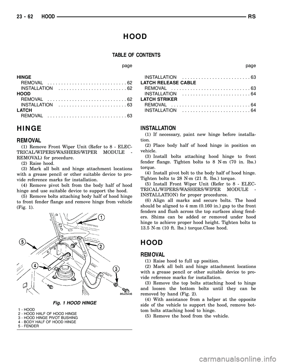
(Fig. 1).
INSTALLATION
(1) If necessary, paint new hinge before installa-
tion.
(2) Place body half of hood hinge in position on
vehicle.
(3) Install bolts attaching hood hinge to front
fender flange. Tighten bolts to 8 N´m (70 in. lbs.)
torque.
(4) Install pivot bolt to the body half of hood hinge.
Tighten bolts to 28 N´m (21 ft. lbs.) torque.
(5) Install Front Wiper Unit (Refer to 8 - ELEC-
TRICAL/WIPERS/WASHERS/WIPER MODULE -
INSTALLATION) for proper procedures.
(6) Align all marks and secure bolts. The hood
should be aligned to 4 mm (0.160 in.) gap to the front
fenders and flush across the top surfaces along fend-
ers. Shims can be added or removed under hood
hinge to achieve proper hood height. Tighten bolts to
13.5 N´m (10 ft. lbs.) torque.Close hood.
HOOD
REMOVAL
(1) Raise hood to full up position.
(2) Mark all bolt and hinge attachment locations
with a grease pencil or other suitable device to pro-
vide reference marks for installation.
(3) Remove the top bolts attaching hood to hinge
and loosen the bottom bolts until they can be
removed by hand (Fig. 2).
(4) With assistance from a helper at the opposite
side of the vehicle to support the hood, remove bot-
tom bolts attaching hood to hinge.
(5) Remove the hood from the vehicle.
Fig. 1 HOOD HINGE
1 - HOOD
2 - HOOD HALF OF HOOD HINGE
3 - HOOD HINGE PIVOT BUSHING
4 - BODY HALF OF HOOD HINGE
5 - FENDER
23 - 62 HOODRS
Page 1844 of 2339
INSTRUMENT PANEL
TABLE OF CONTENTS
page page
CLUSTER BEZEL
REMOVAL.............................65
INSTALLATION.........................65
CUP HOLDER
REMOVAL.............................65
INSTALLATION.........................65
GLOVE BOX
REMOVAL.............................66
INSTALLATION.........................66
GLOVE BOX LATCH
REMOVAL.............................66
INSTALLATION.........................66
GLOVE BOX LATCH STRIKER
REMOVAL.............................66
INSTALLATION.........................66
INSTRUMENT PANEL ASSEMBLY
REMOVAL.............................67
INSTALLATION.........................70
INSTRUMENT PANEL CENTER BEZEL
REMOVAL.............................71
INSTALLATION.........................72
INSTRUMENT PANEL RIGHT END CAP
REMOVAL.............................72INSTALLATION.........................72
INSTRUMENT PANEL TOP COVER
REMOVAL.............................72
INSTALLATION.........................72
LOWER CONSOLE
REMOVAL.............................73
INSTALLATION.........................73
LOWER INSTRUMENT PANEL
REMOVAL.............................73
INSTALLATION.........................73
LOWER STEERING COLUMN COVER
REMOVAL.............................74
INSTALLATION.........................74
BLOCKER- INFLATABLE KNEE
REMOVAL.............................75
INSTALLATION.........................75
OVER STEERING COLUMN COVER
REMOVAL.............................76
INSTALLATION.........................76
INSTRUMENT PANEL TOP PAD ASSEMBLY
REMOVAL.............................77
INSTALLATION.........................77
CLUSTER BEZEL
REMOVAL
(1) Disconnect and isolate the battery negative
cable.
(2) Remove Over Steering Column Bezel by lifting
it straight up with a firm pull.
(3) Remove the four bezel attaching screws (Fig.
1).
(4) Tilt the steering column in the full down posi-
tion.
(5) Pull rearward on the cluster bezel and remove.
INSTALLATION
(1) Maneuver cluster bezel over steering column
and into position (Fig. 1).
(2) Install the four bezel attaching screws.
(3) Install the Over Steering Column Bezel by
positioning it over the retaining slots and firmly
snapping it into place.
(4) Connect the battery negative cable.
CUP HOLDER
REMOVAL
(1) Remove the screw access cover from the bottom
of the center bezel.
(2) Remove the center bezel attaching screws.
(3) Using a trim stick (special tool # C-4755) or
equivalent, gently pry out on the edge of the instru-
ment panel center bezel. Hang off to the side leaving
the accessory switches connected.
(4) Pull the cup holder assembly rearward to dis-
engage the rear guide studs from instrument panel
(Fig. 2).
(5) Remove the cup holder assembly from lower
instrument panel.
INSTALLATION
(1) Ensure the cup holder assembly is in the closed
position. The cup holder assembly must be installed
as an assembly to ensure proper track position.
(2) Place the cup holder assembly into position in
the lower instrument panel and slide into opening
until the rear guide struts snap into place (Fig. 2).
(3) Install the center bezel.
RSINSTRUMENT PANEL23-65
Page 1857 of 2339
INTERIOR
TABLE OF CONTENTS
page page
A-PILLAR LOWER EXTENSION TRIM
REMOVAL.............................79
INSTALLATION.........................79
A-PILLAR TRIM
REMOVAL.............................79
INSTALLATION.........................79
ASSIST HANDLE
REMOVAL.............................79
INSTALLATION.........................79
B-PILLAR LOWER TRIM
REMOVAL.............................79
INSTALLATION.........................80
B-PILLAR UPPER TRIM
REMOVAL.............................80
INSTALLATION.........................80
CARPETS AND FLOOR MATS
REMOVAL.............................81
INSTALLATION.........................81
CARPETS - FOLD-IN-FLOOR
REMOVAL.............................82
INSTALLATION.........................83
CARPET TRIM RING AND COVER - FOLD-IN-
FLOOR
REMOVAL.............................84
INSTALLATION.........................84
COWL TRIM
REMOVAL.............................88
INSTALLATION.........................88
C-PILLAR TRIM
REMOVAL.............................88
INSTALLATION.........................88
DOOR SILL TRIM PLATE
REMOVAL.............................89
INSTALLATION.........................89
FLOOR CONSOLE BASE TRAY
REMOVAL.............................89
INSTALLATION.........................89
FLOOR CONSOLE - FOLD-IN-FLOOR
REMOVAL.............................89
INSTALLATION.........................89
FLOOR CONSOLE KEY LOCK TUMBLER -
FOLD-IN-FLOOR
REMOVAL.............................90
INSTALLATION.........................90
FLOOR CONSOLE LID LATCH - FOLD-IN-
FLOOR
REMOVAL.............................90
INSTALLATION.........................90HEADLINER
REMOVAL.............................91
INSTALLATION.........................92
LEFT D-PILLAR TRIM PANEL
REMOVAL.............................94
INSTALLATION.........................94
LEFT QUARTER TRIM PANEL
REMOVAL.............................94
INSTALLATION.........................94
LIFTGATE SILL PLATE
REMOVAL.............................94
INSTALLATION.........................95
QUARTER TRIM BOLSTER
REMOVAL.............................95
INSTALLATION.........................95
REAR FLOOR TUB CARPETS INSERT -
FOLD-IN-FLOOR
REMOVAL.............................95
INSTALLATION.........................96
REAR HEADER TRIM
REMOVAL.............................96
INSTALLATION.........................96
REAR HVAC LOUVER
REMOVAL.............................96
INSTALLATION.........................97
RIGHT QUARTER TRIM PANEL
REMOVAL.............................97
INSTALLATION.........................97
REAR VIEW MIRROR
REMOVAL.............................97
INSTALLATION.........................97
RIGHT D-PILLAR TRIM PANEL
REMOVAL.............................97
INSTALLATION.........................98
SECOND ROW FLOOR TUB CARPET INSERT -
FOLD-IN-FLOOR
REMOVAL.............................98
INSTALLATION.........................98
SLIDING DOOR SILL PLATE
REMOVAL.............................98
INSTALLATION.........................99
SUN VISOR
REMOVAL.............................99
INSTALLATION.........................99
SUN VISOR SUPPORT
REMOVAL.............................99
INSTALLATION.........................99
23 - 78 INTERIORRS
Page 1879 of 2339
PAINT
TABLE OF CONTENTS
page page
PAINT
SPECIFICATIONS - COLOR CODE CHARTS . . 100
BASE COAT/CLEARCOAT FINISH
DESCRIPTION........................101
PAINT CODE
DESCRIPTION........................101PAINTED TOUCH-UP
DESCRIPTION........................101
FINESSE SANDING/BUFFING & POLISHING
DESCRIPTION........................101
PAINT
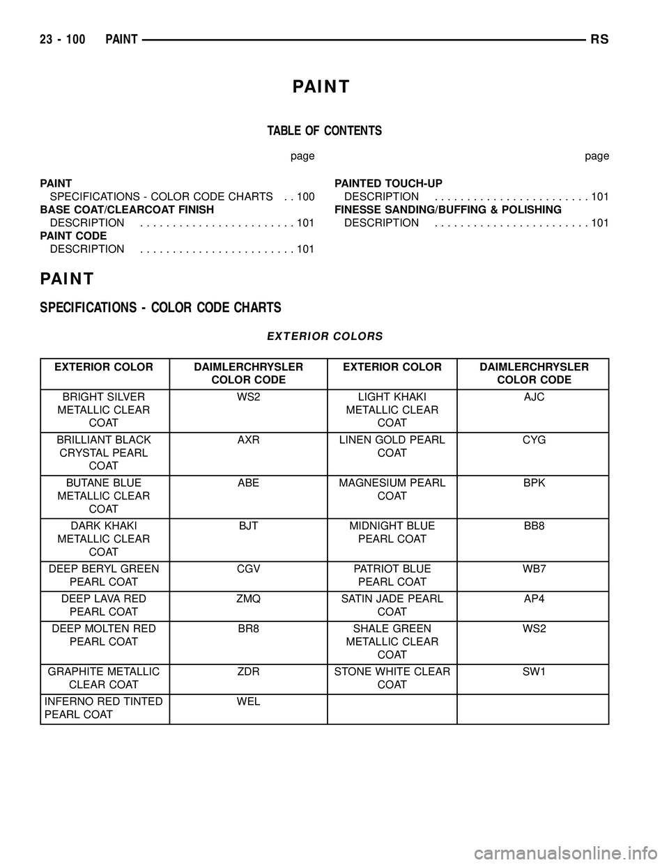
SPECIFICATIONS - COLOR CODE CHARTS
EXTERIOR COLORS
EXTERIOR COLOR DAIMLERCHRYSLER
COLOR CODEEXTERIOR COLOR DAIMLERCHRYSLER
COLOR CODE
BRIGHT SILVER
METALLIC CLEAR
COATWS2 LIGHT KHAKI
METALLIC CLEAR
COATAJC
BRILLIANT BLACK
CRYSTAL PEARL
COATAXR LINEN GOLD PEARL
COATCYG
BUTANE BLUE
METALLIC CLEAR
COATABE MAGNESIUM PEARL
COATBPK
DARK KHAKI
METALLIC CLEAR
COATBJT MIDNIGHT BLUE
PEARL COATBB8
DEEP BERYL GREEN
PEARL COATCGV PATRIOT BLUE
PEARL COATWB7
DEEP LAVA RED
PEARL COATZMQ SATIN JADE PEARL
COATAP4
DEEP MOLTEN RED
PEARL COATBR8 SHALE GREEN
METALLIC CLEAR
COATWS2
GRAPHITE METALLIC
CLEAR COATZDR STONE WHITE CLEAR
COATSW1
INFERNO RED TINTED
PEARL COATWEL
23 - 100 PAINTRS
Page 1881 of 2339
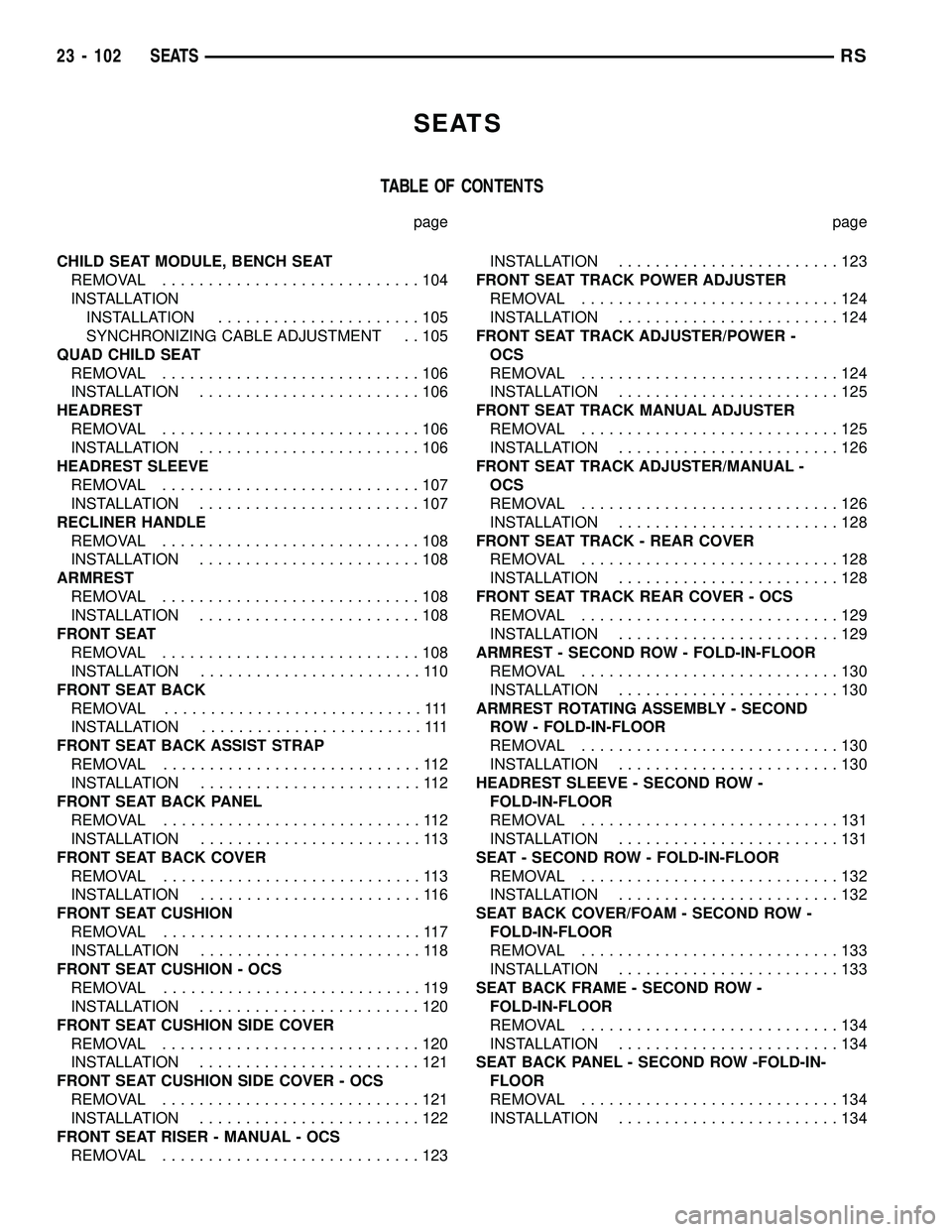
SEATS
TABLE OF CONTENTS
page page
CHILD SEAT MODULE, BENCH SEAT
REMOVAL............................104
INSTALLATION
INSTALLATION......................105
SYNCHRONIZING CABLE ADJUSTMENT . . 105
QUAD CHILD SEAT
REMOVAL............................106
INSTALLATION........................106
HEADREST
REMOVAL............................106
INSTALLATION........................106
HEADREST SLEEVE
REMOVAL............................107
INSTALLATION........................107
RECLINER HANDLE
REMOVAL............................108
INSTALLATION........................108
ARMREST
REMOVAL............................108
INSTALLATION........................108
FRONT SEAT
REMOVAL............................108
INSTALLATION........................110
FRONT SEAT BACK
REMOVAL............................111
INSTALLATION........................111
FRONT SEAT BACK ASSIST STRAP
REMOVAL............................112
INSTALLATION........................112
FRONT SEAT BACK PANEL
REMOVAL............................112
INSTALLATION........................113
FRONT SEAT BACK COVER
REMOVAL............................113
INSTALLATION........................116
FRONT SEAT CUSHION
REMOVAL............................117
INSTALLATION........................118
FRONT SEAT CUSHION - OCS
REMOVAL............................119
INSTALLATION........................120
FRONT SEAT CUSHION SIDE COVER
REMOVAL............................120
INSTALLATION........................121
FRONT SEAT CUSHION SIDE COVER - OCS
REMOVAL............................121
INSTALLATION........................122
FRONT SEAT RISER - MANUAL - OCS
REMOVAL............................123INSTALLATION........................123
FRONT SEAT TRACK POWER ADJUSTER
REMOVAL............................124
INSTALLATION........................124
FRONT SEAT TRACK ADJUSTER/POWER -
OCS
REMOVAL............................124
INSTALLATION........................125
FRONT SEAT TRACK MANUAL ADJUSTER
REMOVAL............................125
INSTALLATION........................126
FRONT SEAT TRACK ADJUSTER/MANUAL -
OCS
REMOVAL............................126
INSTALLATION........................128
FRONT SEAT TRACK - REAR COVER
REMOVAL............................128
INSTALLATION........................128
FRONT SEAT TRACK REAR COVER - OCS
REMOVAL............................129
INSTALLATION........................129
ARMREST - SECOND ROW - FOLD-IN-FLOOR
REMOVAL............................130
INSTALLATION........................130
ARMREST ROTATING ASSEMBLY - SECOND
ROW - FOLD-IN-FLOOR
REMOVAL............................130
INSTALLATION........................130
HEADREST SLEEVE - SECOND ROW -
FOLD-IN-FLOOR
REMOVAL............................131
INSTALLATION........................131
SEAT - SECOND ROW - FOLD-IN-FLOOR
REMOVAL............................132
INSTALLATION........................132
SEAT BACK COVER/FOAM - SECOND ROW -
FOLD-IN-FLOOR
REMOVAL............................133
INSTALLATION........................133
SEAT BACK FRAME - SECOND ROW -
FOLD-IN-FLOOR
REMOVAL............................134
INSTALLATION........................134
SEAT BACK PANEL - SECOND ROW -FOLD-IN-
FLOOR
REMOVAL............................134
INSTALLATION........................134
23 - 102 SEATSRS
Page 1940 of 2339
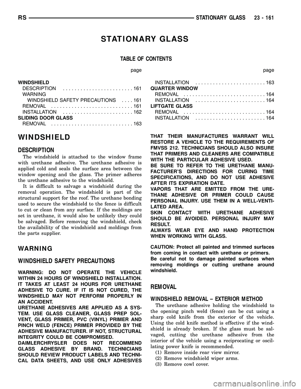
STATIONARY GLASS
TABLE OF CONTENTS
page page
WINDSHIELD
DESCRIPTION........................161
WARNING
WINDSHIELD SAFETY PRECAUTIONS....161
REMOVAL............................161
INSTALLATION........................162
SLIDING DOOR GLASS
REMOVAL............................163INSTALLATION........................163
QUARTER WINDOW
REMOVAL............................164
INSTALLATION........................164
LIFTGATE GLASS
REMOVAL............................164
INSTALLATION........................164
WINDSHIELD
DESCRIPTION
The windshield is attached to the window frame
with urethane adhesive. The urethane adhesive is
applied cold and seals the surface area between the
window opening and the glass. The primer adheres
the urethane adhesive to the windshield.
It is difficult to salvage a windshield during the
removal operation. The windshield is part of the
structural support for the roof. The urethane bonding
used to secure the windshield to the fence is difficult
to cut or clean from any surface. If the moldings are
set in urethane, it would also be unlikely they could
be salvaged. Before removing the windshield, check
the availability of the windshield and moldings from
the parts supplier.
WARNING
WINDSHIELD SAFETY PRECAUTIONS
WARNING: DO NOT OPERATE THE VEHICLE
WITHIN 24 HOURS OF WINDSHIELD INSTALLATION.
IT TAKES AT LEAST 24 HOURS FOR URETHANE
ADHESIVE TO CURE. IF IT IS NOT CURED, THE
WINDSHIELD MAY NOT PERFORM PROPERLY IN
AN ACCIDENT.
URETHANE ADHESIVES ARE APPLIED AS A SYS-
TEM. USE GLASS CLEANER, GLASS PREP SOL-
VENT, GLASS PRIMER, PVC (VINYL) PRIMER AND
PINCH WELD (FENCE) PRIMER PROVIDED BY THE
ADHESIVE MANUFACTURER. IF NOT, STRUCTURAL
INTEGRITY COULD BE COMPROMISED.
DAIMLERCHRYSLER DOES NOT RECOMMEND
GLASS ADHESIVE BY BRAND. TECHNICIANS
SHOULD REVIEW PRODUCT LABELS AND TECHNI-
CAL DATA SHEETS, AND USE ONLY ADHESIVESTHAT THEIR MANUFACTURES WARRANT WILL
RESTORE A VEHICLE TO THE REQUIREMENTS OF
FMVSS 212. TECHNICIANS SHOULD ALSO INSURE
THAT PRIMERS AND CLEANERS ARE COMPATIBLE
WITH THE PARTICULAR ADHESIVE USED.
BE SURE TO REFER TO THE URETHANE MANU-
FACTURER'S DIRECTIONS FOR CURING TIME
SPECIFICATIONS, AND DO NOT USE ADHESIVE
AFTER ITS EXPIRATION DATE.
VAPORS THAT ARE EMITTED FROM THE URE-
THANE ADHESIVE OR PRIMER COULD CAUSE
PERSONAL INJURY. USE THEM IN A WELL-VENTI-
LATED AREA.
SKIN CONTACT WITH URETHANE ADHESIVE
SHOULD BE AVOIDED. PERSONAL INJURY MAY
RESULT.
ALWAYS WEAR EYE AND HAND PROTECTION
WHEN WORKING WITH GLASS.
CAUTION: Protect all painted and trimmed surfaces
from coming in contact with urethane or primers.
Be careful not to damage painted surfaces when
removing moldings or cutting urethane around
windshield.
REMOVAL
WINDSHIELD REMOVAL ± EXTERIOR METHOD
The urethane adhesive holding the windshield to
the opening pinch weld (fence) can be cut using a
sharp cold knife from the exterior of the vehicle.
Using the cold knife method is effective if the wind-
shield is already broken. If the glass must be sal-
vaged, cutting the urethane adhesive from the
interior of the vehicle using a reciprocating or oscil-
lating power knife is recommended.
(1) Remove inside rear view mirror.
(2) Remove windshield wiper arms.
(3) Remove cowl cover.
RSSTATIONARY GLASS23 - 161
Page 1945 of 2339
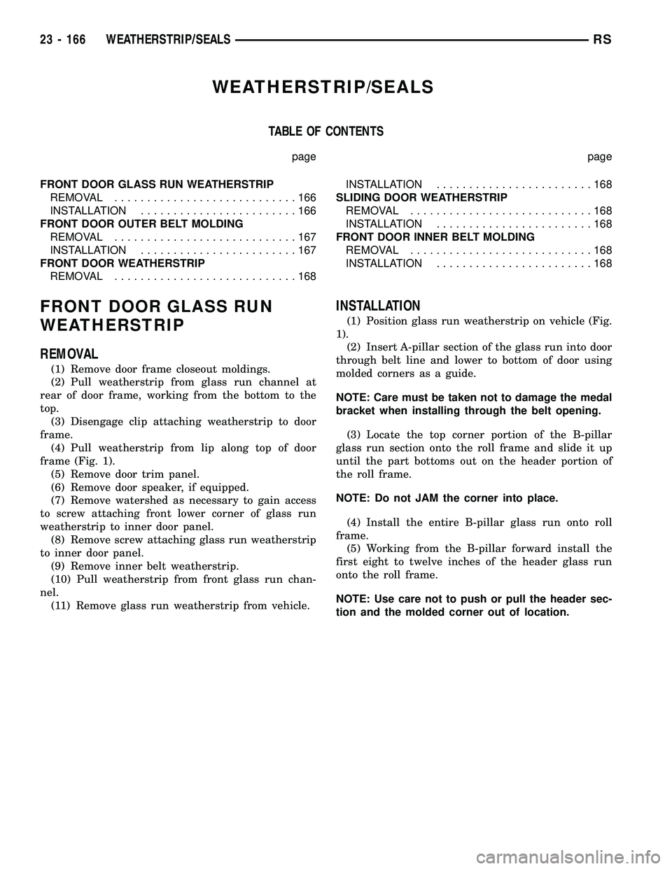
WEATHERSTRIP/SEALS
TABLE OF CONTENTS
page page
FRONT DOOR GLASS RUN WEATHERSTRIP
REMOVAL............................166
INSTALLATION........................166
FRONT DOOR OUTER BELT MOLDING
REMOVAL............................167
INSTALLATION........................167
FRONT DOOR WEATHERSTRIP
REMOVAL............................168INSTALLATION........................168
SLIDING DOOR WEATHERSTRIP
REMOVAL............................168
INSTALLATION........................168
FRONT DOOR INNER BELT MOLDING
REMOVAL............................168
INSTALLATION........................168
FRONT DOOR GLASS RUN
WEATHERSTRIP
REMOVAL
(1) Remove door frame closeout moldings.
(2) Pull weatherstrip from glass run channel at
rear of door frame, working from the bottom to the
top.
(3) Disengage clip attaching weatherstrip to door
frame.
(4) Pull weatherstrip from lip along top of door
frame (Fig. 1).
(5) Remove door trim panel.
(6) Remove door speaker, if equipped.
(7) Remove watershed as necessary to gain access
to screw attaching front lower corner of glass run
weatherstrip to inner door panel.
(8) Remove screw attaching glass run weatherstrip
to inner door panel.
(9) Remove inner belt weatherstrip.
(10) Pull weatherstrip from front glass run chan-
nel.
(11) Remove glass run weatherstrip from vehicle.
INSTALLATION
(1) Position glass run weatherstrip on vehicle (Fig.
1).
(2) Insert A-pillar section of the glass run into door
through belt line and lower to bottom of door using
molded corners as a guide.
NOTE: Care must be taken not to damage the medal
bracket when installing through the belt opening.
(3) Locate the top corner portion of the B-pillar
glass run section onto the roll frame and slide it up
until the part bottoms out on the header portion of
the roll frame.
NOTE: Do not JAM the corner into place.
(4) Install the entire B-pillar glass run onto roll
frame.
(5) Working from the B-pillar forward install the
first eight to twelve inches of the header glass run
onto the roll frame.
NOTE: Use care not to push or pull the header sec-
tion and the molded corner out of location.
23 - 166 WEATHERSTRIP/SEALSRS