2005 CHRYSLER VOYAGER check engine
[x] Cancel search: check enginePage 1235 of 2339
INSPECTION
(1) Inspect the mating surfaces of the oil pump
cover. Surface should be smooth. Replace pump cover
if scratched or grooved.
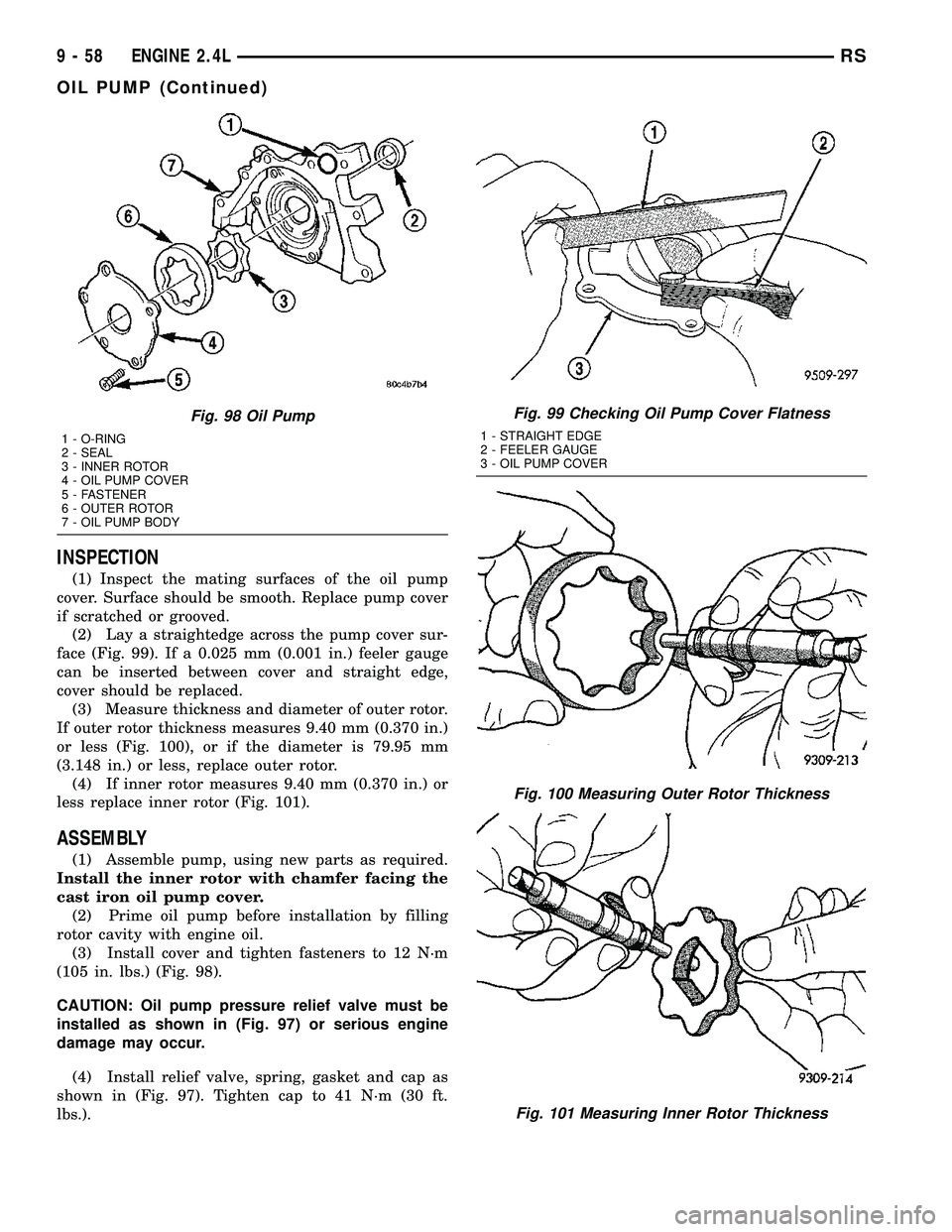
(2) Lay a straightedge across the pump cover sur-
face (Fig. 99). If a 0.025 mm (0.001 in.) feeler gauge
can be inserted between cover and straight edge,
cover should be replaced.
(3) Measure thickness and diameter of outer rotor.
If outer rotor thickness measures 9.40 mm (0.370 in.)
or less (Fig. 100), or if the diameter is 79.95 mm
(3.148 in.) or less, replace outer rotor.
(4) If inner rotor measures 9.40 mm (0.370 in.) or
less replace inner rotor (Fig. 101).
ASSEMBLY
(1) Assemble pump, using new parts as required.
Install the inner rotor with chamfer facing the
cast iron oil pump cover.
(2) Prime oil pump before installation by filling
rotor cavity with engine oil.
(3) Install cover and tighten fasteners to 12 N´m
(105 in. lbs.) (Fig. 98).
CAUTION: Oil pump pressure relief valve must be
installed as shown in (Fig. 97) or serious engine
damage may occur.
(4) Install relief valve, spring, gasket and cap as
shown in (Fig. 97). Tighten cap to 41 N´m (30 ft.
lbs.).
Fig. 98 Oil Pump
1 - O-RING
2 - SEAL
3 - INNER ROTOR
4 - OIL PUMP COVER
5 - FASTENER
6 - OUTER ROTOR
7 - OIL PUMP BODY
Fig. 99 Checking Oil Pump Cover Flatness
1 - STRAIGHT EDGE
2 - FEELER GAUGE
3 - OIL PUMP COVER
Fig. 100 Measuring Outer Rotor Thickness
Fig. 101 Measuring Inner Rotor Thickness
9 - 58 ENGINE 2.4LRS
OIL PUMP (Continued)
Page 1238 of 2339
(9) Disconnect throttle and speed control (if
equipped) cables from throttle lever and bracket.
(Refer to 14 - FUEL SYSTEM/FUEL INJECTION/
THROTTLE CONTROL CABLE - REMOVAL)
(10) Remove the EGR tube. (Refer to 25 - EMIS-
SIONS CONTROL/EXHAUST GAS RECIRCULA-
TION/TUBE - REMOVAL)
(11) Remove the upper manifold support bracket
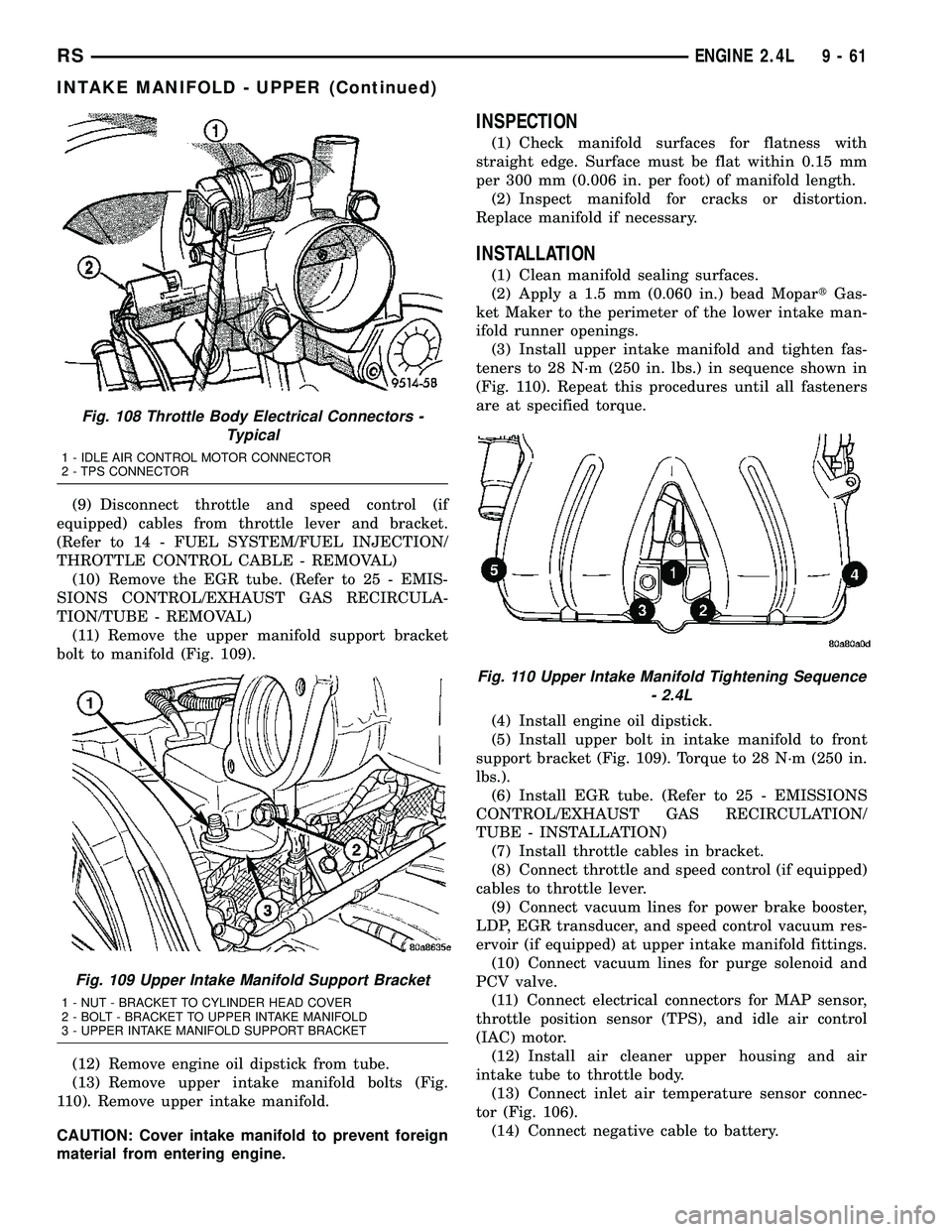
bolt to manifold (Fig. 109).
(12) Remove engine oil dipstick from tube.
(13) Remove upper intake manifold bolts (Fig.
110). Remove upper intake manifold.
CAUTION: Cover intake manifold to prevent foreign
material from entering engine.
INSPECTION
(1) Check manifold surfaces for flatness with
straight edge. Surface must be flat within 0.15 mm
per 300 mm (0.006 in. per foot) of manifold length.
(2) Inspect manifold for cracks or distortion.
Replace manifold if necessary.
INSTALLATION
(1) Clean manifold sealing surfaces.
(2) Apply a 1.5 mm (0.060 in.) bead MopartGas-
ket Maker to the perimeter of the lower intake man-
ifold runner openings.
(3) Install upper intake manifold and tighten fas-
teners to 28 N´m (250 in. lbs.) in sequence shown in
(Fig. 110). Repeat this procedures until all fasteners
are at specified torque.
(4) Install engine oil dipstick.
(5) Install upper bolt in intake manifold to front
support bracket (Fig. 109). Torque to 28 N´m (250 in.
lbs.).
(6) Install EGR tube. (Refer to 25 - EMISSIONS
CONTROL/EXHAUST GAS RECIRCULATION/
TUBE - INSTALLATION)
(7) Install throttle cables in bracket.
(8) Connect throttle and speed control (if equipped)
cables to throttle lever.
(9) Connect vacuum lines for power brake booster,
LDP, EGR transducer, and speed control vacuum res-
ervoir (if equipped) at upper intake manifold fittings.
(10) Connect vacuum lines for purge solenoid and
PCV valve.
(11) Connect electrical connectors for MAP sensor,
throttle position sensor (TPS), and idle air control
(IAC) motor.
(12) Install air cleaner upper housing and air
intake tube to throttle body.
(13) Connect inlet air temperature sensor connec-
tor (Fig. 106).
(14) Connect negative cable to battery.
Fig. 108 Throttle Body Electrical Connectors -
Typical
1 - IDLE AIR CONTROL MOTOR CONNECTOR
2 - TPS CONNECTOR
Fig. 109 Upper Intake Manifold Support Bracket
1 - NUT - BRACKET TO CYLINDER HEAD COVER
2 - BOLT - BRACKET TO UPPER INTAKE MANIFOLD
3 - UPPER INTAKE MANIFOLD SUPPORT BRACKET
Fig. 110 Upper Intake Manifold Tightening Sequence
- 2.4L
RSENGINE 2.4L9-61
INTAKE MANIFOLD - UPPER (Continued)
Page 1239 of 2339

INTAKE MANIFOLD - LOWER
REMOVAL
(1) Perform fuel system pressure release proce-
durebefore attempting any repairs.(Refer to 14 -
FUEL SYSTEM/FUEL DELIVERY - STANDARD
PROCEDURE)
(2) Remove upper intake manifold. (Refer to 9 -
ENGINE/MANIFOLDS/INTAKE MANIFOLD -
REMOVAL)
CAUTION: Cover intake manifold openings to pre-
vent foreign material from entering engine.
(3) Disconnect fuel line. (Refer to 14 - FUEL SYS-
TEM/FUEL DELIVERY/QUICK CONNECT FIT-
TING - STANDARD PROCEDURE)
(4) Drain the cooling system. (Refer to 7 - COOL-
ING - STANDARD PROCEDURE)
(5) Remove heater supply and radiator upper
hoses at intake manifold.
(6) Disconnect coolant temperature sensor/fuel
injector wire harness connector.
(7) Remove lower intake manifold support bracket
upper bolts (Fig. 111).
(8) Loosen the lower intake manfold support
bracket lower bolt (Fig. 111).
(9) Disconnect fuel injector harness.
(10) Remove the bolts attaching the power steering
reservoir to manifold. Set reservoir aside.Do not
disconnect line from reservoir.
(11) Remove lower intake manifold fasteners (Fig.
112). Remove the manifold from engine.(12) Inspect the manifold. (Refer to 9 - ENGINE/
MANIFOLDS/INTAKE MANIFOLD - INSPECTION)INSPECTION
(1) Check manifold surfaces for flatness with
straight edge. Surface must be flat within 0.15 mm
per 300 mm (0.006 in. per foot) of manifold length.
(2) Inspect manifold for cracks or distortion.
Replace manifold if necessary.
INSTALLATION
If the following items were removed, install and
torque to specifications:
²Fuel rail bolts - 22 N´m (200 in. lbs.)
²Coolant outlet connector bolts - 28 N´m (250 in.
lbs.)
²Coolant temperature sensor - 7 N´m (60 in. lbs.)
(1) Position a new gasket on cylinder head and
install lower manifold.
(2) Install and tighten intake manifold fasteners to
28 N´m (250 in. lbs.) in the sequence shown in (Fig.
112). Repeat procedure until all bolts are at specified
torque.
(3) Install lower intake manifold support bracket
bolts (Fig. 111) and tighten to:
²Bolts to intake 28 N´m (250 in. lbs.)
²Bolt to engine block 54 N´m (40 ft. lbs.)
(4) Position power steering reservoir on manifold
and install bolts.
(5) Connect the fuel line. (Refer to 14 - FUEL SYS-
TEM/FUEL DELIVERY/QUICK CONNECT FIT-
TING - STANDARD PROCEDURE)
(6) Connect coolant temperature sensor/fuel injec-
tor wiring harness electrical connector.
(7) Install the radiator upper and heater supply
hoses.
Fig. 111 Lower Intake Manifold Support Bracket
1 - SUPPORT BRACKET
2 - BOLTS - UPPER TO MANIFOLD
3 - BOLT - LOWER TO ENGINE BLOCK
Fig. 112 Lower Intake Manifold Tightening Sequence
9 - 62 ENGINE 2.4LRS
Page 1246 of 2339
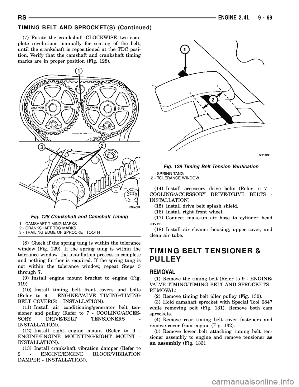
(7) Rotate the crankshaft CLOCKWISE two com-
plete revolutions manually for seating of the belt,
until the crankshaft is repositioned at the TDC posi-
tion. Verify that the camshaft and crankshaft timing
marks are in proper position (Fig. 128).
(8) Check if the spring tang is within the tolerance
window (Fig. 129). If the spring tang is within the
tolerance window, the installation process is complete
and nothing further is required. If the spring tang is
not within the tolerance window, repeat Steps 5
through 7.
(9) Install engine mount bracket to engine (Fig.
119).
(10) Install timing belt front covers and bolts
(Refer to 9 - ENGINE/VALVE TIMING/TIMING
BELT COVER(S) - INSTALLATION).
(11) Install air conditioning/generator belt ten-
sioner and pulley (Refer to 7 - COOLING/ACCES-
SORY DRIVE/BELT TENSIONERS -
INSTALLATION).
(12) Install right engine mount (Refer to 9 -
ENGINE/ENGINE MOUNTING/RIGHT MOUNT -
INSTALLATION).
(13) Install crankshaft vibration damper (Refer to
9 - ENGINE/ENGINE BLOCK/VIBRATION
DAMPER - INSTALLATION).(14) Install accessory drive belts (Refer to 7 -
COOLING/ACCESSORY DRIVE/DRIVE BELTS -
INSTALLATION).
(15) Install drive belt splash shield.
(16) Install right front wheel.
(17) Connect make-up air hose to cylinder head
cover.
(18) Install air cleaner housing, upper cover, and
clean air tube.
TIMING BELT TENSIONER &
PULLEY
REMOVAL
(1) Remove the timing belt (Refer to 9 - ENGINE/
VALVE TIMING/TIMING BELT AND SPROCKETS -
REMOVAL).
(2) Remove timing belt idler pulley (Fig. 130).
(3) Hold camshaft sprocket with Special Tool 6847
while removing bolt (Fig. 131). Remove both cam
sprockets.
(4) Remove rear timing belt cover fasteners and
remove cover from engine (Fig. 132).
(5) Remove lower bolt attaching timing belt ten-
sioner assembly to engine and remove tensioneras
an assembly(Fig. 133).
Fig. 128 Crankshaft and Camshaft Timing
1 - CAMSHAFT TIMING MARKS
2 - CRANKSHAFT TDC MARKS
3 - TRAILING EDGE OF SPROCKET TOOTH
Fig. 129 Timing Belt Tension Verification
1 - SPRING TANG
2 - TOLERANCE WINDOW
RSENGINE 2.4L9-69
TIMING BELT AND SPROCKET(S) (Continued)
Page 1254 of 2339
INSPECTION..........................115
HYDRAULIC LIFTERS (CAM IN BLOCK)
DESCRIPTION........................116
DIAGNOSIS AND TESTING - HYDRAULIC
LIFTERS...........................116
REMOVAL............................117
INSTALLATION........................117
CAMSHAFT & BEARINGS (IN BLOCK)
DESCRIPTION........................118
OPERATION..........................118
REMOVAL............................118
INSPECTION..........................118
INSTALLATION........................118
PISTON & CONNECTING ROD
DESCRIPTION........................119
STANDARD PROCEDURE
STANDARD PROCEDURE - FITTING
CONNECTING RODS..................119
STANDARD PROCEDURE - FITTING
PISTONS...........................120
REMOVAL............................120
INSTALLATION........................121
CONNECTING ROD BEARINGS
STANDARD PROCEDURE - MEASURING
CONNECTING ROD BEARING
CLEARANCE........................123
PISTON RINGS
STANDARD PROCEDURE - PISTON RING
FITTING............................124
REMOVAL............................124
INSTALLATION........................124
CRANKSHAFT MAIN BEARINGS
STANDARD PROCEDURE - MAIN BEARING
FITTING............................125
REMOVAL - CRANKSHAFT MAIN BEARINGS . 127
INSTALLATION - CRANKSHAFT MAIN
BEARINGS..........................127
CRANKSHAFT
DESCRIPTION
DESCRIPTION - 3.3L..................128
DESCRIPTION - 3.8L..................128
STANDARD PROCEDURE - MEASURING
CRANKSHAFT END PLAY..............128
REMOVAL............................128
INSTALLATION........................129
CRANKSHAFT OIL SEAL - FRONT
REMOVAL............................130
INSTALLATION........................130
CRANKSHAFT OIL SEAL - REAR
REMOVAL............................131
INSTALLATION........................131
CRANKSHAFT REAR OIL SEAL RETAINER
REMOVAL............................132
INSTALLATION........................132
VIBRATION DAMPER
REMOVAL............................132
INSTALLATION........................132FLEX PLATE
REMOVAL............................133
INSTALLATION........................133
ENGINE MOUNTING
DESCRIPTION........................134
FRONT MOUNT
REMOVAL............................134
INSTALLATION........................134
LEFT MOUNT
REMOVAL............................136
INSTALLATION........................136
REAR MOUNT
REMOVAL............................136
INSTALLATION........................137
RIGHT MOUNT
REMOVAL............................138
INSTALLATION........................138
LUBRICATION
DESCRIPTION........................138
OPERATION..........................138
DIAGNOSIS AND TESTING - ENGINE OIL
PRESSURE.........................138
OIL
STANDARD PROCEDURE
STANDARD PROCEDURE - ENGINE OIL
AND FILTER CHANGE.................139
STANDARD PROCEDURE - ENGINE OIL
LEVEL CHECK.......................140
OIL COOLER & LINES
DESCRIPTION........................141
OPERATION..........................141
REMOVAL............................141
INSTALLATION........................141
OIL FILTER
REMOVAL............................141
INSTALLATION........................141
OIL FILTER ADAPTER
REMOVAL............................142
INSTALLATION........................142
OIL PAN
REMOVAL............................142
CLEANING...........................142
INSPECTION.........................143
INSTALLATION........................143
OIL PRESSURE RELIEF VALVE
REMOVAL............................143
INSTALLATION........................144
OIL PRESSURE SWITCH
DESCRIPTION........................144
OPERATION..........................144
REMOVAL............................144
INSTALLATION........................144
OIL PUMP
DESCRIPTION........................144
REMOVAL............................144
DISASSEMBLY........................145
CLEANING...........................145
RSENGINE 3.3/3.8L9-77
Page 1257 of 2339
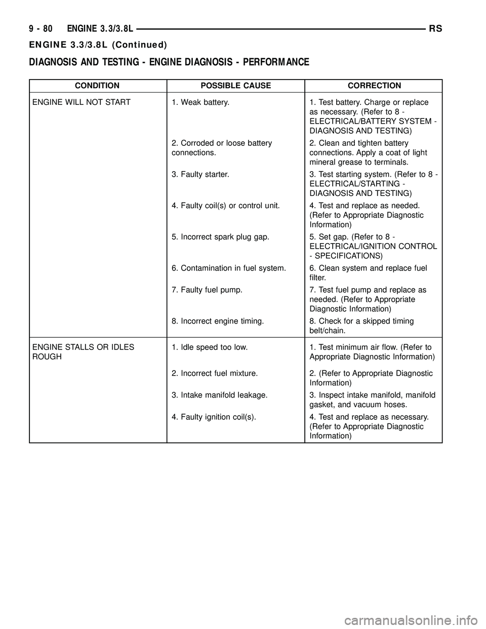
DIAGNOSIS AND TESTING - ENGINE DIAGNOSIS - PERFORMANCE
CONDITION POSSIBLE CAUSE CORRECTION
ENGINE WILL NOT START 1. Weak battery. 1. Test battery. Charge or replace
as necessary. (Refer to 8 -
ELECTRICAL/BATTERY SYSTEM -
DIAGNOSIS AND TESTING)
2. Corroded or loose battery
connections.2. Clean and tighten battery
connections. Apply a coat of light
mineral grease to terminals.
3. Faulty starter. 3. Test starting system. (Refer to 8 -
ELECTRICAL/STARTING -
DIAGNOSIS AND TESTING)
4. Faulty coil(s) or control unit. 4. Test and replace as needed.
(Refer to Appropriate Diagnostic
Information)
5. Incorrect spark plug gap. 5. Set gap. (Refer to 8 -
ELECTRICAL/IGNITION CONTROL
- SPECIFICATIONS)
6. Contamination in fuel system. 6. Clean system and replace fuel
filter.
7. Faulty fuel pump. 7. Test fuel pump and replace as
needed. (Refer to Appropriate
Diagnostic Information)
8. Incorrect engine timing. 8. Check for a skipped timing
belt/chain.
ENGINE STALLS OR IDLES
ROUGH1. Idle speed too low. 1. Test minimum air flow. (Refer to
Appropriate Diagnostic Information)
2. Incorrect fuel mixture. 2. (Refer to Appropriate Diagnostic
Information)
3. Intake manifold leakage. 3. Inspect intake manifold, manifold
gasket, and vacuum hoses.
4. Faulty ignition coil(s). 4. Test and replace as necessary.
(Refer to Appropriate Diagnostic
Information)
9 - 80 ENGINE 3.3/3.8LRS
ENGINE 3.3/3.8L (Continued)
Page 1259 of 2339
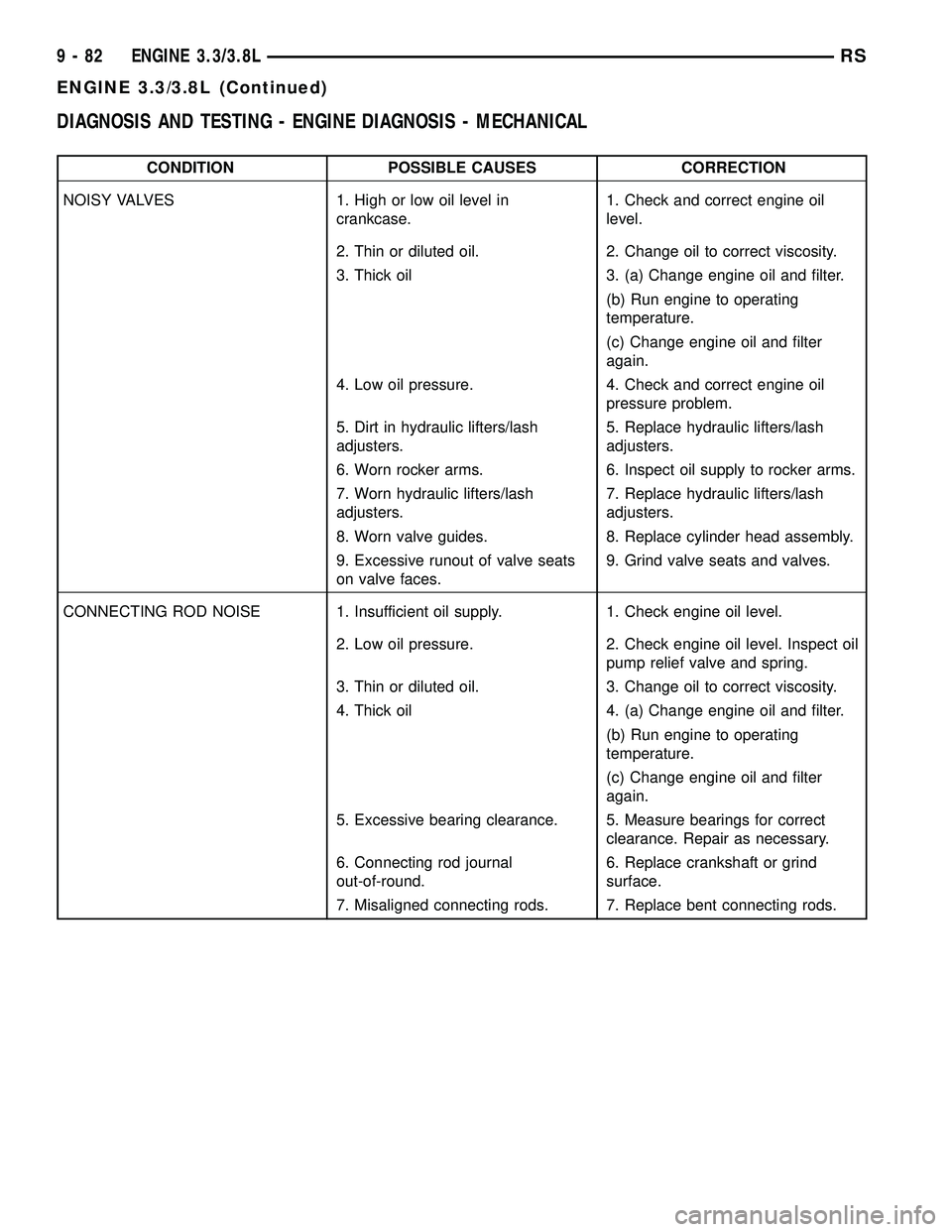
DIAGNOSIS AND TESTING - ENGINE DIAGNOSIS - MECHANICAL
CONDITION POSSIBLE CAUSES CORRECTION
NOISY VALVES 1. High or low oil level in
crankcase.1. Check and correct engine oil
level.
2. Thin or diluted oil. 2. Change oil to correct viscosity.
3. Thick oil 3. (a) Change engine oil and filter.
(b) Run engine to operating
temperature.
(c) Change engine oil and filter
again.
4. Low oil pressure. 4. Check and correct engine oil
pressure problem.
5. Dirt in hydraulic lifters/lash
adjusters.5. Replace hydraulic lifters/lash
adjusters.
6. Worn rocker arms. 6. Inspect oil supply to rocker arms.
7. Worn hydraulic lifters/lash
adjusters.7. Replace hydraulic lifters/lash
adjusters.
8. Worn valve guides. 8. Replace cylinder head assembly.
9. Excessive runout of valve seats
on valve faces.9. Grind valve seats and valves.
CONNECTING ROD NOISE 1. Insufficient oil supply. 1. Check engine oil level.
2. Low oil pressure. 2. Check engine oil level. Inspect oil
pump relief valve and spring.
3. Thin or diluted oil. 3. Change oil to correct viscosity.
4. Thick oil 4. (a) Change engine oil and filter.
(b) Run engine to operating
temperature.
(c) Change engine oil and filter
again.
5. Excessive bearing clearance. 5. Measure bearings for correct
clearance. Repair as necessary.
6. Connecting rod journal
out-of-round.6. Replace crankshaft or grind
surface.
7. Misaligned connecting rods. 7. Replace bent connecting rods.
9 - 82 ENGINE 3.3/3.8LRS
ENGINE 3.3/3.8L (Continued)
Page 1260 of 2339
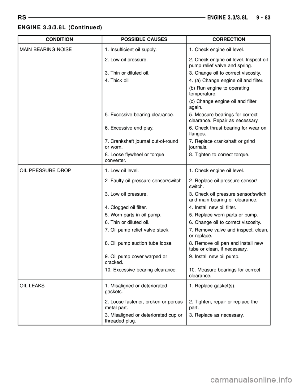
CONDITION POSSIBLE CAUSES CORRECTION
MAIN BEARING NOISE 1. Insufficient oil supply. 1. Check engine oil level.
2. Low oil pressure. 2. Check engine oil level. Inspect oil
pump relief valve and spring.
3. Thin or diluted oil. 3. Change oil to correct viscosity.
4. Thick oil 4. (a) Change engine oil and filter.
(b) Run engine to operating
temperature.
(c) Change engine oil and filter
again.
5. Excessive bearing clearance. 5. Measure bearings for correct
clearance. Repair as necessary.
6. Excessive end play. 6. Check thrust bearing for wear on
flanges.
7. Crankshaft journal out-of-round
or worn.7. Replace crankshaft or grind
journals.
8. Loose flywheel or torque
converter.8. Tighten to correct torque.
OIL PRESSURE DROP 1. Low oil level. 1. Check engine oil level.
2. Faulty oil pressure sensor/switch. 2. Replace oil pressure sensor/
switch.
3. Low oil pressure. 3. Check oil pressure sensor/switch
and main bearing oil clearance.
4. Clogged oil filter. 4. Install new oil filter.
5. Worn parts in oil pump. 5. Replace worn parts or pump.
6. Thin or diluted oil. 6. Change oil to correct viscosity.
7. Oil pump relief valve stuck. 7. Remove valve and inspect, clean,
or replace.
8. Oil pump suction tube loose. 8. Remove oil pan and install new
tube or clean, if necessary.
9. Oil pump cover warped or
cracked.9. Install new oil pump.
10. Excessive bearing clearance. 10. Measure bearings for correct
clearance.
OIL LEAKS 1. Misaligned or deteriorated
gaskets.1. Replace gasket(s).
2. Loose fastener, broken or porous
metal part.2. Tighten, repair or replace the
part.
3. Misaligned or deteriorated cup or
threaded plug.3. Replace as necessary.
RSENGINE 3.3/3.8L9-83
ENGINE 3.3/3.8L (Continued)