2005 CHRYSLER CARAVAN oil level
[x] Cancel search: oil levelPage 1765 of 2339
REMOVAL
REMOVAL - TIRE AND WHEEL ASSEMBLY
(ALUMINUM WHEEL)
(1) Raise the vehicle so the tire and wheel assem-
bly clears ground level.
(2) Remove the 5 wheel mounting nuts from the
studs.
(3) Remove the tire and wheel from the hub.
REMOVAL - TIRE AND WHEEL ASSEMBLY
(STEEL WHEEL)
(1) Raise the vehicle so the tire and wheel assem-
bly clears ground level.
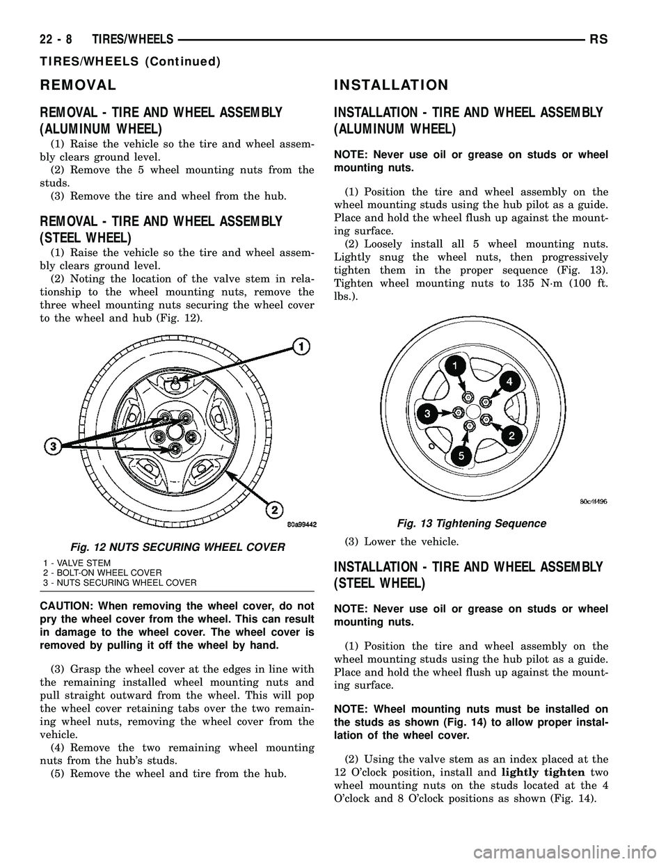
(2) Noting the location of the valve stem in rela-
tionship to the wheel mounting nuts, remove the
three wheel mounting nuts securing the wheel cover
to the wheel and hub (Fig. 12).
CAUTION: When removing the wheel cover, do not
pry the wheel cover from the wheel. This can result
in damage to the wheel cover. The wheel cover is
removed by pulling it off the wheel by hand.
(3) Grasp the wheel cover at the edges in line with
the remaining installed wheel mounting nuts and
pull straight outward from the wheel. This will pop
the wheel cover retaining tabs over the two remain-
ing wheel nuts, removing the wheel cover from the
vehicle.
(4) Remove the two remaining wheel mounting
nuts from the hub's studs.
(5) Remove the wheel and tire from the hub.
INSTALLATION
INSTALLATION - TIRE AND WHEEL ASSEMBLY
(ALUMINUM WHEEL)
NOTE: Never use oil or grease on studs or wheel
mounting nuts.
(1) Position the tire and wheel assembly on the
wheel mounting studs using the hub pilot as a guide.
Place and hold the wheel flush up against the mount-
ing surface.
(2) Loosely install all 5 wheel mounting nuts.
Lightly snug the wheel nuts, then progressively
tighten them in the proper sequence (Fig. 13).
Tighten wheel mounting nuts to 135 N´m (100 ft.
lbs.).
(3) Lower the vehicle.
INSTALLATION - TIRE AND WHEEL ASSEMBLY
(STEEL WHEEL)
NOTE: Never use oil or grease on studs or wheel
mounting nuts.
(1) Position the tire and wheel assembly on the
wheel mounting studs using the hub pilot as a guide.
Place and hold the wheel flush up against the mount-
ing surface.
NOTE: Wheel mounting nuts must be installed on
the studs as shown (Fig. 14) to allow proper instal-
lation of the wheel cover.
(2) Using the valve stem as an index placed at the
12 O'clock position, install andlightly tightentwo
wheel mounting nuts on the studs located at the 4
O'clock and 8 O'clock positions as shown (Fig. 14).
Fig. 12 NUTS SECURING WHEEL COVER
1 - VALVE STEM
2 - BOLT-ON WHEEL COVER
3 - NUTS SECURING WHEEL COVER
Fig. 13 Tightening Sequence
22 - 8 TIRES/WHEELSRS
TIRES/WHEELS (Continued)
Page 2152 of 2339
HEATING & AIR CONDITIONING
TABLE OF CONTENTS
page page
HEATING & AIR CONDITIONING
DESCRIPTION
ENGINE COOLING SYSTEM
REQUIREMENTS.......................1
HEATER AND AIR CONDITIONER..........1
MANUAL SINGLE ZONE.................2
MANUAL DUAL ZONE...................2
MANUAL THREE ZONE..................2
AUTOMATIC TEMPERATURE CONTROL....3
OPERATION
HEATER AND AIR CONDITIONER..........4
MANUAL SINGLE ZONE.................4
MANUAL DUAL ZONE...................5
MANUAL THREE ZONE..................5AUTOMATIC TEMPERATURE CONTROL....5
DIAGNOSIS AND TESTING
A/C COOL DOWN TEST.................6
A/C PERFORMANCE TEST...............7
HEATER PERFORMANCE TEST..........10
SPECIFICATIONS
A/C SYSTEM.........................11
CONTROLS - FRONT.....................13
CONTROLS - REAR......................33
DISTRIBUTION - FRONT...................42
DISTRIBUTION - REAR....................56
PLUMBING - FRONT.....................64
PLUMBING - REAR......................98
CABIN HEATER........................113
HEATING & AIR
CONDITIONING
DESCRIPTION
ENGINE COOLING SYSTEM REQUIREMENTS
To maintain the performance level of the heating,
ventilation and air conditioning (HVAC) system, the
engine cooling system must be properly maintained.
The use of a bug screen is not recommended. Any
obstructions in front of the radiator or condenser will
reduce the performance of the air conditioning and
engine cooling systems.
The engine cooling system includes the radiator,
thermostat, radiator hoses and the engine coolant
pump. Refer to Cooling for more information before
opening or attempting any service to the engine cool-
ing system.
HEATER AND AIR CONDITIONER
A manually controlled single zone type heating-air
conditioning system, manually controlled dual zone
type heating-air conditioning system, manually con-
trolled three zone type heating-air conditioning sys-
tem or an automatic controlled three zone type
heating-air conditioning system is available on this
model.
All vehicles are equipped with a common heater,
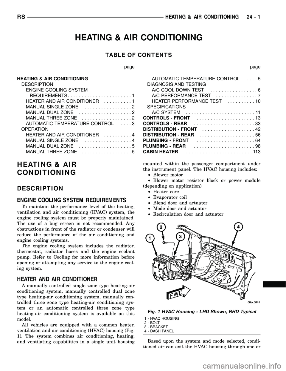
ventilation and air conditioning (HVAC) housing (Fig.
1). The system combines air conditioning, heating,
and ventilating capabilities in a single unit housingmounted within the passenger compartment under
the instrument panel. The HVAC housing includes:
²Blower motor
²Blower motor resistor block or power module
(depending on application)
²Heater core
²Evaporator coil
²Blend door and actuator
²Mode door and actuator
²Recirculation door and actuator
Based upon the system and mode selected, condi-
tioned air can exit the HVAC housing through one or
Fig. 1 HVAC Housing - LHD Shown, RHD Typical
1 - HVAC HOUSING
2 - BOLT
3 - BRACKET
4 - DASH PANEL
RSHEATING & AIR CONDITIONING24-1
Page 2158 of 2339
rator initial temperature, then the cool down test has
been failed and further A/C system diagnosis is
required. If the test is failed, the snowflake icon and
the DELAY text will continue to blink across ignition
cycles until the vehicle has been driven for greater
than 13 km (8 miles).
A/C PERFORMANCE TEST
The A/C system is designed to remove heat and
humidity from the air entering the passenger com-
partment. The evaporator, located in the HVAC hous-
ing, is cooled to temperatures near the freezing point.
As warm damp air passes over the fins in the A/C
evaporator, moisture in the air condenses to water,
dehumidifying the air. Condensation on the evapora-
tor fins reduces the evaporators ability to absorb
heat. During periods of high heat and humidity, an
A/C system will be less effective. With the instru-
ment control set to recirculation mode, only air from
the passenger compartment passes through the A/C
evaporator. As the passenger compartment air dehu-
midifies, A/C performance levels rise.
Humidity has an important bearing on the temper-
ature of the air delivered to the interior of the vehi-
cle. It is important to understand the effect that
humidity has on the performance of the A/C system.
When humidity is high, the A/C evaporator has to
perform a double duty. It must lower the air temper-
ature, and it must lower the temperature of the
moisture in the air that condenses on the evaporator
fins. Condensing the moisture in the air transfers
heat energy into the evaporator fins and tubing. This
reduces the amount of heat the A/C evaporator can
absorb from the air. High humidity greatly reduces
the ability of the A/C evaporator to lower the temper-
ature of the air.
However, evaporator capacity used to reduce the
amount of moisture in the air is not wasted. Wring-
ing some of the moisture out of the air entering the
vehicle adds to the comfort of the passengers.
Although, an owner may expect too much from their
A/C system on humid days. A performance test is the
best way to determine whether the system is per-
forming up to design standards. This test also pro-
vides valuable clues as to the possible cause of
trouble with the A/C system. The ambient air tem-perature in the location where the vehicle will be
tested must be a minimum of 21É C (70É F) for this
test.
PERFORMANCE TEST PROCEDURE
WARNING: REFER TO THE APPLICABLE WARN-
INGS AND CAUTIONS FOR THIS SYSTEM BEFORE
PERFORMING THE FOLLOWING OPERATION (Refer
to 24 - HEATING & AIR CONDITIONING/PLUMBING -
FRONT - WARNING - A/C PLUMBING) and (Refer to
24 - HEATING & AIR CONDITIONING/PLUMBING -
FRONT - CAUTION - A/C PLUMBING).
NOTE: When connecting the service equipment
coupling to the line fitting, verify that the valve of
the coupling is fully closed. This will reduce the
amount of effort required to make the connection.
(1) Connect a tachometer and a manifold gauge
set.
(2) Set the mode control to the Recirculation Mode
position, the temperature control to the full cool posi-
tion and the blower to the highest speed position.
(3) Start the engine and hold at 1,000 rpm with
the A/C compressor clutch engaged.
(4) The engine should be warmed up to operating
temperature with the doors closed and windows
open.
(5) Insert a thermometer in the driver's side center
panel A/C-heater outlet and operate the engine for
five minutes.
(6) If the compressor clutch does not engage, pro-
ceed with diagnosis of the compressor clutch coil.
(Refer to 24 - HEATING & AIR CONDITIONING/
CONTROLS - FRONT/COMPRESSOR CLUTCH
COIL - DIAGNOSIS AND TESTING).
(7) With the A/C compressor clutch engaged, com-
pare the air temperature at the center panel outlet
and the compressor discharge pressure to the A/C
Performance Temperature and Pressure chart. The
compressor clutch may cycle, depending upon the
ambient temperature and humidity. If the clutch
cycles, use the readings obtained before the clutch
disengaged.
RSHEATING & AIR CONDITIONING24-7
HEATING & AIR CONDITIONING (Continued)
Page 2160 of 2339
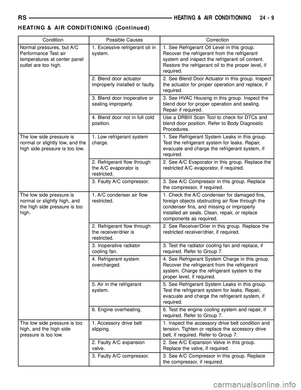
Condition Possible Causes Correction
Normal pressures, but A/C
Performance Test air
temperatures at center panel
outlet are too high.1. Excessive refrigerant oil in
system.1. See Refrigerant Oil Level in this group.
Recover the refrigerant from the refrigerant
system and inspect the refrigerant oil content.
Restore the refrigerant oil to the proper level, if
required.
2. Blend door actuator
improperly installed or faulty.2. See Blend Door Actuator in this group. Inspect
the actuator for proper operation and replace, if
required.
3. Blend door inoperative or
sealing improperly.3. See HVAC Housing in this group. Inspect the
blend door for proper operation and sealing.
Repair if required.
4. Blend door not in full cold
position.Use a DRBIII Scan Tool to check for DTCs and
blend door position. Refer to Body Diagnostic
Procedures.
The low side pressure is
normal or slightly low, and the
high side pressure is too low.1. Low refrigerant system
charge.1. See Refrigerant System Leaks in this group.
Test the refrigerant system for leaks. Repair,
evacuate and charge the refrigerant system, if
required.
2. Refrigerant flow through
the A/C evaporator is
restricted.2. See A/C Evaporator in this group. Replace the
restricted A/C evaporator, if required.
3. Faulty A/C compressor. 3. See A/C Compressor in this group. Replace
the compressor, if required.
The low side pressure is
normal or slightly high, and
the high side pressure is too
high.1. A/C condenser air flow
restricted.1. Check the A/C condenser for damaged fins,
foreign objects obstructing air flow through the
condenser fins, and missing or improperly
installed air seals. Clean, repair, or replace
components as required.
2. Refrigerant flow through
the receiver/drier is
restricted.2. See Receiver/Drier in this group. Replace the
restricted receiver/drier, if required.
3. Inoperative radiator
cooling fan.3. Test the radiator cooling fan and replace, if
required. Refer to Group 7.
4. Refrigerant system
overcharged.4. See Refrigerant System Charge in this group.
Recover the refrigerant from the refrigerant
system. Charge the refrigerant system to the
proper level, if required.
5. Air in the refrigerant
system.5. See Refrigerant System Leaks in this group.
Test the refrigerant system for leaks. Repair,
evacuate and charge the refrigerant system, if
required.
6. Engine overheating. 6. Test the engine cooling system and repair, if
required. Refer to Group 7.
The low side pressure is too
high, and the high side
pressure is too low.1. Accessory drive belt
slipping.1. Inspect the accessory drive belt condition and
tension. Tighten or replace the accessory drive
belt, if required. Refer to Group 7.
2. Faulty A/C expansion
valve.2. See A/C Expansion Valve in this group.
Replace the valve, if required.
3. Faulty A/C compressor. 3. See A/C Compressor in this group. Replace
the compressor, if required.
RSHEATING & AIR CONDITIONING24-9
HEATING & AIR CONDITIONING (Continued)
Page 2165 of 2339
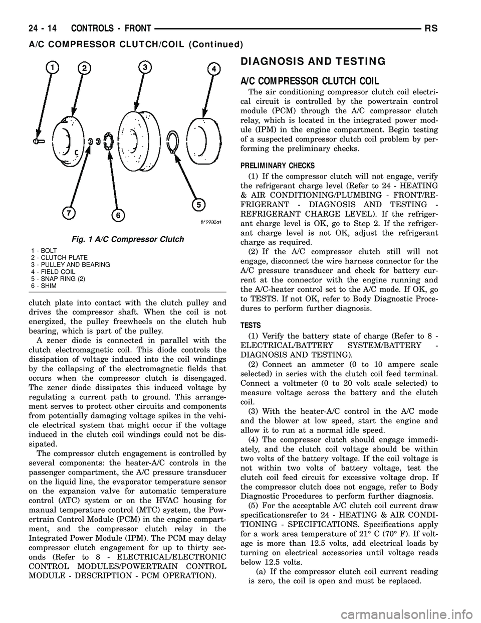
clutch plate into contact with the clutch pulley and
drives the compressor shaft. When the coil is not
energized, the pulley freewheels on the clutch hub
bearing, which is part of the pulley.
A zener diode is connected in parallel with the
clutch electromagnetic coil. This diode controls the
dissipation of voltage induced into the coil windings
by the collapsing of the electromagnetic fields that
occurs when the compressor clutch is disengaged.
The zener diode dissipates this induced voltage by
regulating a current path to ground. This arrange-
ment serves to protect other circuits and components
from potentially damaging voltage spikes in the vehi-
cle electrical system that might occur if the voltage
induced in the clutch coil windings could not be dis-
sipated.
The compressor clutch engagement is controlled by
several components: the heater-A/C controls in the
passenger compartment, the A/C pressure transducer
on the liquid line, the evaporator temperature sensor
on the expansion valve for automatic temperature
control (ATC) system or on the HVAC housing for
manual temperature control (MTC) system, the Pow-
ertrain Control Module (PCM) in the engine compart-
ment, and the compressor clutch relay in the
Integrated Power Module (IPM). The PCM may delay
compressor clutch engagement for up to thirty sec-
onds (Refer to 8 - ELECTRICAL/ELECTRONIC
CONTROL MODULES/POWERTRAIN CONTROL
MODULE - DESCRIPTION - PCM OPERATION).
DIAGNOSIS AND TESTING
A/C COMPRESSOR CLUTCH COIL
The air conditioning compressor clutch coil electri-
cal circuit is controlled by the powertrain control
module (PCM) through the A/C compressor clutch
relay, which is located in the integrated power mod-
ule (IPM) in the engine compartment. Begin testing
of a suspected compressor clutch coil problem by per-
forming the preliminary checks.
PRELIMINARY CHECKS
(1) If the compressor clutch will not engage, verify
the refrigerant charge level (Refer to 24 - HEATING
& AIR CONDITIONING/PLUMBING - FRONT/RE-
FRIGERANT - DIAGNOSIS AND TESTING -
REFRIGERANT CHARGE LEVEL). If the refriger-
ant charge level is OK, go to Step 2. If the refriger-
ant charge level is not OK, adjust the refrigerant
charge as required.
(2) If the A/C compressor clutch still will not
engage, disconnect the wire harness connector for the
A/C pressure transducer and check for battery cur-
rent at the connector with the engine running and
the A/C-heater control set to the A/C mode. If OK, go
to TESTS. If not OK, refer to Body Diagnostic Proce-
dures to perform further diagnosis.
TESTS
(1) Verify the battery state of charge (Refer to 8 -
ELECTRICAL/BATTERY SYSTEM/BATTERY -
DIAGNOSIS AND TESTING).
(2) Connect an ammeter (0 to 10 ampere scale
selected) in series with the clutch coil feed terminal.
Connect a voltmeter (0 to 20 volt scale selected) to
measure voltage across the battery and the clutch
coil.
(3) With the heater-A/C control in the A/C mode
and the blower at low speed, start the engine and
allow it to run at a normal idle speed.
(4) The compressor clutch should engage immedi-
ately, and the clutch coil voltage should be within
two volts of the battery voltage. If the coil voltage is
not within two volts of battery voltage, test the
clutch coil feed circuit for excessive voltage drop. If
the compressor clutch does not engage, refer to Body
Diagnostic Procedures to perform further diagnosis.
(5) For the acceptable A/C clutch coil current draw
specificationsrefer to 24 - HEATING & AIR CONDI-
TIONING - SPECIFICATIONS. Specifications apply
for a work area temperature of 21É C (70É F). If volt-
age is more than 12.5 volts, add electrical loads by
turning on electrical accessories until voltage reads
below 12.5 volts.
(a) If the compressor clutch coil current reading
is zero, the coil is open and must be replaced.
Fig. 1 A/C Compressor Clutch
1 - BOLT
2 - CLUTCH PLATE
3 - PULLEY AND BEARING
4 - FIELD COIL
5 - SNAP RING (2)
6 - SHIM
24 - 14 CONTROLS - FRONTRS
A/C COMPRESSOR CLUTCH/COIL (Continued)
Page 2215 of 2339
PLUMBING - FRONT
TABLE OF CONTENTS
page page
PLUMBING - FRONT
DESCRIPTION.........................65
OPERATION...........................65
WARNING
ENGINE COOLING SYSTEM.............65
A/C SYSTEM.........................66
CAUTION - A/C SYSTEM.................66
DIAGNOSIS AND TESTING
REFRIGERANT SYSTEM LEAKS..........67
SYSTEM CHARGE LEVEL TEST..........67
STANDARD PROCEDURE
HANDLING TUBING AND FITTINGS.......69
REFRIGERANT SYSTEM SERVICE
EQUIPMENT.........................69
REFRIGERANT SYSTEM RECOVERY......70
REFRIGERANT SYSTEM EVACUATE......70
REFRIGERANT SYSTEM CHARGE........71
A/C COMPRESSOR
DESCRIPTION
A/C COMPRESSOR....................72
HIGH PRESSURE RELIEF VALVE.........72
OPERATION
A/C COMPRESSOR....................72
HIGH PRESSURE RELIEF VALVE.........72
DIAGNOSIS AND TESTING
A/C COMPRESSOR NOISE DIAGNOSIS....72
REMOVAL
A/C COMPRESSOR....................73
A/C COMPRESSOR MOUNTING BRACKET -
2.4L ENGINE.........................74
INSTALLATION
A/C COMPRESSOR....................74
A/C COMPRESSOR MOUNTING BRACKET -
2.4L ENGINE.........................75
A/C CONDENSER
DESCRIPTION.........................75
OPERATION...........................75
REMOVAL
2.4L/3.3L/3.8L ENGINES................76
2.5L/2.8L DIESEL ENGINES..............77
INSTALLATION
2.4L/3.3L/3.8L ENGINES................77
2.5L/2.8L DIESEL ENGINES..............78
A/C DISCHARGE LINE
REMOVAL.............................79
INSTALLATION.........................80
A/C EVAPORATOR
DESCRIPTION.........................80OPERATION...........................80
REMOVAL.............................81
INSTALLATION.........................81
EXPANSION VALVE
DESCRIPTION.........................81
OPERATION...........................81
DIAGNOSIS AND TESTING
FRONT A/C EXPANSION VALVE..........82
REMOVAL.............................82
INSTALLATION.........................83
HEATER CORE
DESCRIPTION.........................83
OPERATION...........................84
REMOVAL
FRONT HEATER CORE TUBES...........84
FRONT HEATER CORE.................85
INSTALLATION
FRONT HEATER CORE TUBES...........85
FRONT HEATER CORE.................86
HEATER INLET HOSE
REMOVAL.............................86
INSTALLATION.........................87
HEATER RETURN HOSE
REMOVAL.............................88
INSTALLATION.........................89
LIQUID LINE
REMOVAL.............................89
INSTALLATION.........................91
RECEIVER / DRIER
DESCRIPTION.........................92
OPERATION...........................92
REMOVAL.............................92
INSTALLATION.........................93
REFRIGERANT
DESCRIPTION.........................93
OPERATION...........................94
REFRIGERANT OIL
DESCRIPTION.........................94
OPERATION...........................94
STANDARD PROCEDURE
REFRIGERANT OIL LEVEL..............94
SERVICE PORT VALVE CORE
DESCRIPTION.........................95
REMOVAL.............................95
INSTALLATION.........................95
SUCTION LINE
REMOVAL.............................96
INSTALLATION.........................97
24 - 64 PLUMBING - FRONTRS
Page 2218 of 2339
DIAGNOSIS AND TESTING
REFRIGERANT SYSTEM LEAKS
WARNING: R-134a SERVICE EQUIPMENT OR VEHI-
CLE A/C SYSTEM SHOULD NOT BE PRESSURE
TESTED OR LEAK TESTED WITH COMPRESSED
AIR. MIXTURE OF AIR and R-134a CAN BE COMBUS-
TIBLE AT ELEVATED PRESSURES. THESE MIX-
TURES ARE POTENTIALLY DANGEROUS AND MAY
RESULT IN FIRE OR EXPLOSION CAUSING INJURY
OR PROPERTY DAMAGE.
AVOID BREATHING A/C REFRIGERANT AND LUBRI-
CANT VAPOR OR MIST. EXPOSURE MAY IRRITATE
EYES, NOSE AND THROAT. USE ONLY APPROVED
SERVICE EQUIPMENT MEETING SAE REQUIRE-
MENTS TO DISCHARGE R-134a SYSTEM. IF ACCI-
DENTAL SYSTEM DISCHARGE OCCURS, VENTILATE
WORK AREA BEFORE RESUMING SERVICE.
If the A/C system is not cooling properly, determine
if the refrigerant system is fully charged with R-134a
(Refer to 24 - HEATING & AIR CONDITIONING/
PLUMBING - FRONT/REFRIGERANT - DIAGNO-
SIS AND TESTING - REFRIGERANT SYSTEM
CHARGE LEVEL). If while performing this test A/C
liquid line pressure is less than 345 kPa (50 psi) pro-
ceed to System Empty procedure. If liquid line pres-
sure is greater than 345 kPa (50 psi) proceed to
System Low procedure. If the refrigerant system is
empty or low in refrigerant charge, a leak at any line
fitting or component seal is likely. A review of the fit-
tings, lines and components for oily residue is an
indication of the leak location.
To detect a leak in the refrigerant system, perform
one of the following procedures as indicated by the
results of the refrigerant system charge level test.
SYSTEM EMPTY
(1) Evacuate the refrigerant system to the lowest
degree of vacuum possible (approx. 28 in Hg.) (Refer
to 24 - HEATING & AIR CONDITIONING/PLUMB-
ING - FRONT/REFRIGERANT - STANDARD PRO-
CEDURE - REFRIGERANT SYSTEM EVACUATE).
Determine if the system holds a vacuum for 15 min-
utes. If vacuum is held, a leak is probably not
present. If system will not maintain vacuum level,
proceed with this procedure.
(2) Prepare a 0.284 Kg. (10 oz.) refrigerant charge
to be injected into the system.
(3) Connect and dispense 0.284 Kg. (10 oz.) of
refrigerant into the evacuated refrigerant system
(Refer to 24 - HEATING & AIR CONDITIONING/
PLUMBING - FRONT/REFRIGERANT - STANDARD
PROCEDURE - REFRIGERANT SYSTEM CHARGE).
(4) Proceed to the SYSTEM LOW procedures.SYSTEM LOW
(1) Position the vehicle in a wind-free work area.
This will aid in detecting small leaks.
(2) Bring the refrigerant system up to operating
temperature and pressure. This is done by allowing
the engine to run for five minutes with the system
set to the following:
²Transaxle in Park
²Engine idling
²Rear A/C Off (if equipped)
²A/C controls set to 100 percent outside air
²Blower switch in the highest speed position
²A/C in the ON position
²Front windows open
CAUTION: A leak detector designed for R-12 refrig-
erant (only) will not detect leaks in a R-134a refrig-
erant system.
(3) Shut off the vehicle and wait 2 to 7 minutes.
Then use an Electronic Leak Detector that is
designed to detect R-134a type refrigerant and search
for leaks. Fittings, lines, or components that appear
to be oily usually indicates a refrigerant leak. To
inspect the evaporator core for leaks, insert the leak
detector probe into the drain tube opening or a heat
duct. A R-134a dye is available to aid in leak detec-
tion, use only DaimlerChrysler approved refrigerant
dye.
SYSTEM CHARGE LEVEL TEST
WARNING: REFER TO THE APPLICABLE WARN-
INGS AND CAUTIONS FOR THIS SYSTEM BEFORE
PERFORMING THE FOLLOWING OPERATION (Refer
to 24 - HEATING & AIR CONDITIONING/PLUMBING -
FRONT - WARNING - A/C PLUMBING) and (Refer to
24 - HEATING & AIR CONDITIONING/PLUMBING -
FRONT - CAUTION - A/C PLUMBING).
NOTE: Always refer to the underhood HVAC Speci-
fication Label for the refrigerant fill specification of
the vehicle being serviced.
The procedure that follows should be used to deter-
mine whether the refrigerant system contains the
proper refrigerant charge. Symptoms of an improper
refrigerant charge (low) include: poor air conditioner
performance, fog emitted from the air conditioner
outlets, a hissing sound from the expansion valve/
evaporator area. There are two different methods
with which the refrigerant charge level may be
tested:
1. Using a DRBIIItscan tool, a thermocouple and
the Charge Determination Chart (Fig. 1). Refer to
the appropriate diagnostic information.
RSPLUMBING - FRONT24-67
PLUMBING - FRONT (Continued)
Page 2220 of 2339
(4) Raise the liquid line (discharge) pressure to
about 1793 kPa (260 psi) by placing a piece of card-
board over part of the front side of the condenser. To
place the cardboard properly, remove the upper radi-
ator sight shield from the front fascia. Cover only
enough of the condenser to raise and maintain the
liquid line pressure at the specified level.
(5) Observe the liquid line (discharge) pressure
and liquid line temperature. Using the Charge Deter-
mination Chart (Fig. 1), determine whether the
refrigerant system is operating within the Proper
Charge Range.
(a) If the refrigerant system is operating in the
Undercharged area of the chart, add 0.057 kilo-
gram (0.125 pound or 2 ounces) of refrigerant to
the system.
(b) If the refrigerant system is operating in the
Overcharged area of the chart, reclaim 0.057 kilo-
gram (0.125 pound or 2 ounces) of refrigerant from
the system.
(6) Recheck the system charge level following each
refrigerant adjustment. Continue this process until
the system readings are in the Proper Charge Range
area on the Charge Determination Chart.
STANDARD PROCEDURE
HANDLING TUBING AND FITTINGS
CAUTION: The system must be completely empty
before opening any fitting or connection in the
refrigeration system. Open fittings with caution
even after the system has been emptied. If any
pressure is noticed as a fitting is loosened,
retighten fitting and evacuate the system again.
A good rule for the flexible hose lines is to keep the
radius of all bends at least 10 times the diameter of
the hose. Sharper bends will reduce the flow of
refrigerant. The flexible hose lines should be routed
so they are at least 3 inches (80 mm) from the
exhaust manifold. Inspect all flexible hose lines to
make sure they are in good condition and properly
routed.
The use of correct wrenches when making connec-
tions is very important. Improper wrenches or
improper use of wrenches can damage the fittings.
The internal parts of the A/C system will remain sta-
ble as long as moisture-free refrigerant and refrig-
erant oil is used. Abnormal amounts of dirt,
moisture or air can upset the chemical stability.
This may cause operational troubles or even seri-
ous damage if present in more than very small
quantities. Before disconnecting a component,
clean the outside of the fittings thoroughly to pre-
vent contamination from entering the refrigerant
system.When opening a refrigeration system, have every-
thing you will need to repair the system ready. This
will minimize the amount of time the system must
be opened. Cap or plug all lines and fittings as
soon as they are opened. This will help prevent the
entrance of dirt and moisture. All new lines and
components should be capped or sealed until they
are ready to be used. Before connecting a compo-
nent, clean the outside of the fittings thoroughly to
prevent contamination from entering the refrigerant
system.
All tools, including the refrigerant dispensing mani-
fold, the manifold gauge set, and test hoses should
be kept clean and dry.
Kinks in the refrigerant tubing or sharp bends in
the refrigerant hose lines will greatly reduce the
capacity of the entire system. High pressures are pro-
duced in the system when it is operating. Extreme
care must be exercised to make sure that all connec-
tions are pressure tight. Dirt and moisture can enter
the system when it is opened for repair or replace-
ment of lines or components. The refrigerant oil will
absorb moisture readily out of the air. This moisture
will convert into acids within a closed system.
REFRIGERANT SYSTEM SERVICE EQUIPMENT
WARNING: EYE PROTECTION MUST BE WORN
WHEN SERVICING AN AIR CONDITIONING REFRIG-
ERANT SYSTEM. TURN OFF (ROTATE CLOCKWISE)
ALL VALVES ON THE EQUIPMENT BEING USED
BEFORE CONNECTING TO, OR DISCONNECTING
FROM THE REFRIGERANT SYSTEM. FAILURE TO
OBSERVE THESE WARNINGS MAY RESULT IN PER-
SONAL INJURY.
WARNING: REVIEW THE WARNINGS AND CAU-
TIONS IN THE FRONT OF THIS SECTION BEFORE
PERFORMING THE FOLLOWING OPERATION (Refer
to 24 - HEATING & AIR CONDITIONING/PLUMBING -
WARNING) and (Refer to 24 - HEATING & AIR CON-
DITIONING/PLUMBING - CAUTION).
RECOVERY/RECYCLING STATION
When servicing the air conditioning system, a
R-134a refrigerant recovery/recycling/charging sta-
tion that meets SEA Standard J2210 must be used
(Fig. 2). Contact an automotive service equipment
supplier for refrigerant recovery/recycling/charging
equipment. See the operating instructions supplied
by the equipment manufacturer for proper care and
use of this equipment.
RSPLUMBING - FRONT24-69
PLUMBING - FRONT (Continued)