2005 CHRYSLER CARAVAN oil level
[x] Cancel search: oil levelPage 2222 of 2339
If a compressor designed to use R-134a refrigerant
is left open to the atmosphere for an extended period
of time. It is recommended that the refrigerant oil be
drained and replaced with new oil or a new compres-
sor be used. This will eliminate the possibility of con-
taminating the refrigerant system.
If the refrigerant system has been open to the
atmosphere, it must be evacuated before the system
can be filled. Moisture and air mixed with the refrig-
erant will raise the compressor head pressure above
acceptable operating levels. This will reduce the per-
formance of the air conditioner and damage the com-
pressor. Moisture will boil at near room temperature
when exposed to vacuum. A R-134a refrigerant recov-
ery/recycling/charging station that meets SAE Stan-
dard J2210 must be used to evacuate the refrigerant
system. See the operating instructions supplied by
the equipment manufacturer for proper care and use
of this equipment. To evacuate the refrigerant sys-
tem, use the following procedure:
NOTE: When connecting the service equipment
couplings to the refrigerant system service ports,
be certain that the valve of each coupling is fully
closed. This will reduce the amount of effort
required to make the connection.
(1) Recover the refrigerant system (Refer to 24 -
HEATING & AIR CONDITIONING/PLUMBING -
STANDARD PROCEDURE).
(2) Connect a suitable charging station, refrigerant
recovery machine or a manifold gauge set with vac-
uum pump and refrigerant recovery equipment.
(3) Open the suction and discharge valves and
start the vacuum pump. The vacuum pump should
run a minimum of 45 minutes prior to charge to
eliminate all moisture in system. When the suction
gauge reads -88 kPa (-26 in. Hg) vacuum or greater
for 30 minutes, close all valves and turn off vacuum
pump. If the system fails to reach specified vacuum,
the refrigerant system likely has a leak that must be
corrected. If the refrigerant system maintains speci-
fied vacuum for at least 30 minutes, start the vac-
uum pump, open the suction and discharge valves.
Then allow the system to evacuate an additional 10
minutes.
(4) Close all valves. Turn off and disconnect the
vacuum pump.
(5) Charge the refrigerant system (Refer to 24 -
HEATING & AIR CONDITIONING/PLUMBING -
STANDARD PROCEDURE).REFRIGERANT SYSTEM CHARGE
WARNING: REFER TO THE APPLICABLE WARN-
INGS AND CAUTIONS FOR THIS SYSTEM BEFORE
PERFORMING THE FOLLOWING OPERATION (Refer
to 24 - HEATING & AIR CONDITIONING/PLUMBING -
FRONT - WARNING - A/C PLUMBING) and (Refer to
24 - HEATING & AIR CONDITIONING/PLUMBING -
FRONT - CAUTION - A/C PLUMBING).
After all refrigerant system leaks have been
repaired and the refrigerant system has been evacu-
ated, a refrigerant charge can be injected into the
system. For the proper amount of the refrigerant
charge, refer to REFRIGERANT CHARGE CAPAC-
ITY. A R-134a refrigerant recovery/recycling/charging
station that meets SAE Standard J2210 must be
used to charge the refrigerant system with R-134a
refrigerant. See the operating instructions supplied
by the equipment manufacturer for proper care and
use of this equipment.
REFRIGERANT CHARGE CAPACITY
NOTE: Always refer to the underhood HVAC Speci-
fication Label for the refrigerant fill specification of
the vehicle being serviced.
CHARGING PROCEDURE
CAUTION: A small amount of refrigerant oil is
removed from the A/C system each time the refrig-
erant system is recovered and evacuated. Before
charging the A/C system, you MUST replenish any
oil lost during the recovery process. Refer the
equipment manufacturer instructions for more infor-
mation.
(1) Evacuate the refrigerant system. (Refer to 24 -
HEATING & AIR CONDITIONING/PLUMBING -
FRONT/REFRIGERANT - STANDARD PROCE-
DURE - REFRIGERANT SYSTEM EVACUATE).
(2) A manifold gauge set and a R-134a refrigerant
recovery/recycling/charging station that meets SAE
Standard J2210 should still be connected to the
refrigerant system.
(3) Measure the proper amount of refrigerant and
heat it to 52É C (125É F) with the charging station.
See the operating instructions supplied by the equip-
ment manufacturer for proper use of this equipment.
RSPLUMBING - FRONT24-71
PLUMBING - FRONT (Continued)
Page 2223 of 2339
(4) Open both the suction and discharge valves,
then open the charge valve to allow the heated
refrigerant to flow into the system.
(5) When the transfer of refrigerant has stopped,
close both the suction and discharge valves.
(6) If all of the refrigerant charge did not transfer
from the dispensing device, open all of the windows
in the vehicle and set the heater-air conditioner con-
trols so that the compressor is engaged and the
blower motor is operating at its lowest speed setting.
Run the engine at a steady high idle (about 1400
rpm). If the compressor will not engage, test the com-
pressor clutch control circuit and repair as required.
(7) Open the suction valve to allow the remaining
refrigerant to transfer to the refrigerant system.
WARNING: TAKE CARE NOT TO OPEN THE DIS-
CHARGE (HIGH PRESSURE) VALVE AT THIS TIME.
(8) Close the suction valve and test the system
performance. (Refer to 24 - HEATING & AIR CON-
DITIONING - STANDARD PROCEDURE - A/C PER-
FORMANCE TEST).
(9) Disconnect the charging station and manifold
gauge set from the refrigerant system service ports.
(10) Reinstall the caps onto the refrigerant system
service ports.
(11) Run the HVAC Control Cooldown test to ver-
ify proper operation(Refer to 24 - HEATING & AIR
CONDITIONING - DIAGNOSIS AND TESTING).
A/C COMPRESSOR
DESCRIPTION
A/C COMPRESSOR
Vehicles equipped with the 2.4L gasoline, 2.5L die-
sel, 2.8L diesel and 3.3L gasoline engines with the
front heating-A/C system only, use the Denso 10S17
A/C compressor. Vehicles equipped with the 3.3L and
the 3.8L gasoline engines with the optional rear heat-
ing-A/C system use the Denso 10S20 A/C compressor.
Both A/C compressors include an integral high pres-
sure relief valve. The A/C compressor is secured to a
mounting bracket on the 2.4L gasoline engine and
directly to the cylinder block on the 2.5L diesel, 2.8L
diesel, 3.3L gasoline and 3.8L gasoline engines.
HIGH PRESSURE RELIEF VALVE
A high pressure relief valve is located on the rear
of the A/C compressor. This mechanical valve is
designed to vent refrigerant from the A/C system to
protect against damage to the compressor and other
system components, caused by condenser air flow
restriction or an overcharge of refrigerant.
OPERATION
A/C COMPRESSOR
The A/C compressor is driven by the engine
through an electric clutch, drive pulley and belt
arrangement. The compressor is lubricated by refrig-
erant oil that is circulated throughout the refrigerant
system with the refrigerant.
The compressor draws in low-pressure refrigerant
vapor from the evaporator through its suction port. It
then compresses the refrigerant into a high-pressure,
high-temperature refrigerant vapor. The compressor
pumps the high-pressure refrigerant vapor to the
condenser through the compressor discharge port.
The compressor cannot be repaired. If faulty or
damaged, the entire compressor assembly must be
replaced. The compressor clutch, pulley and clutch
coil are available for service.
HIGH PRESSURE RELIEF VALVE
The high pressure relief valve vents the system
when a discharge pressure of 3445 to 4135 kPa (500
to 600 psi) or above is reached. The valve closes
when a minimum discharge pressure of 2756 kPa
(400 psi) is reached.
The high pressure relief valve vents only enough
refrigerant to reduce the system pressure, and then
re-seats itself. The majority of the refrigerant is con-
served in the system. If the valve vents refrigerant, it
does not mean that the valve is faulty.
The high pressure relief valve is a factory-cali-
brated unit. The valve cannot be adjusted or
repaired, and must not be removed or otherwise dis-
turbed. The valve is only serviced as a part of the
compressor assembly.
DIAGNOSIS AND TESTING
A/C COMPRESSOR NOISE DIAGNOSIS
Excessive noise while the air conditioning compres-
sor is operating can be caused by loose compressor
mounts, a loose compressor clutch, or high operating
pressures in the refrigerant system. Verify compres-
sor drive belt condition, proper compressor mounting,
correct refrigerant charge level, and compressor head
pressure before compressor repair is performed.
With the close tolerances within the compressor, it
is possible to experience a temporary lockup. The
longer the compressor is inactive, the more likely the
condition is to occur. This condition is the result of
normal refrigerant migration within the refrigerant
system caused by ambient temperature changes. The
refrigerant migration may wash the refrigerant oil
out of the compressor.
24 - 72 PLUMBING - FRONTRS
PLUMBING - FRONT (Continued)
Page 2224 of 2339
NOTE: Prior to a vehicle being removed from ser-
vice or stored for more than two weeks, the com-
pressor should be operated to ensure adequate
refrigerant oil distribution throughout the system
components. Turn on the air conditioner for a min-
imum of five minutes with outside air and the high-
est blower speed selected.
BELT NOISE
If the compressor drive belt slips at initial start-up,
it does not necessarily mean the compressor has
failed. The following procedure can be used to iden-
tify a compressor drive belt noise problem.
A. Start the vehicle and run at idle.
B. Turn the air conditioner On and listen for belt
squeal.
C. If belt squeal is heard, turn the air conditioner
Off immediately.
If the belt squeal stops when the air conditioner is
turned Off, perform the following repair procedures.
(1) Using an appropriate sized oil filter wrench or
a strap wrench, grasp the outer diameter of the com-
pressor clutch hub. While facing the compressor,
rotate the hub clockwise, then counterclockwise. If
the hub rotates, proceed to the next step. If the hub
will not rotate, the compressor is internally damaged,
and must be replaced.
(2) Turn the hub clockwise five complete revolu-
tions and remove the tool.
(3) Start the vehicle and run at idle.
(4) Turn the air conditioner On. Observe the com-
pressor and the system for normal operation, noting
cooling performance and noise levels. Operate for five
minutes before turning the air conditioner Off. If
acceptable cooling performance is observed during
compressor operation, the compressor does not need
to be replaced.
(5) Inspect the drive belt for wear, damage, and
proper tension. (Refer to 7 - COOLING/ACCESSORY
DRIVE/DRIVE BELTS - DIAGNOSIS AND TEST-
ING).
REMOVAL
A/C COMPRESSOR
WARNING: REFER TO THE APPLICABLE WARN-
INGS AND CAUTIONS FOR THIS SYSTEM BEFORE
PERFORMING THE FOLLOWING OPERATION (Refer
to 24 - HEATING & AIR CONDITIONING/PLUMBING -
FRONT - WARNING - A/C PLUMBING) and (Refer to
24 - HEATING & AIR CONDITIONING/PLUMBING -
FRONT - CAUTION - A/C PLUMBING).(1) Recover the refrigerant from the refrigerant
system (Refer to 24 - HEATING & AIR CONDITION-
ING/PLUMBING - FRONT/REFRIGERANT - STAN-
DARD PROCEDURE - REFRIGERANT SYSTEM
RECOVERY).
(2) Disconnect and isolate the negative battery
cable.
(3) Remove the nuts that secure the A/C suction
line and the A/C discharge line to the A/C compres-
sor.
(4) Disconnect the A/C suction line and the A/C
discharge line from the A/C compressor.
(5) Remove the O-ring seal and gasket from the
suction and discharge line fittings and discard.
(6) Install plugs in, or tape over the opened suc-
tion and discharge fittings and the compressor ports.
(7) Raise and support the vehicle.
(8) Remove the accessory drive belt (Refer to 7 -
COOLING/ACCESSORY DRIVE/DRIVE BELTS -
REMOVAL).
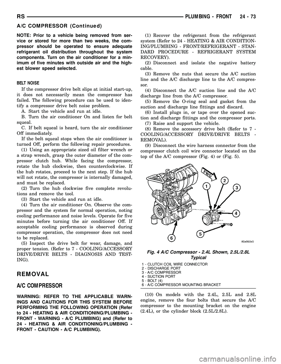
(9) Disconnect the wire harness connector from the
compressor clutch coil wire connector located on the
top of the A/C compressor (Fig. 4) or (Fig. 5).
(10) On models with the 2.4L, 2.5L and 2.8L
engine, remove the four bolts that secure the A/C
compressor to the mounting bracket on the engine
(2.4L), or the cylinder block (2.5L/2.8L).
Fig. 4 A/C Compressor - 2.4L Shown, 2.5L/2.8L
Typical
1 - CLUTCH COIL WIRE CONNECTOR
2 - DISCHARGE PORT
3 - A/C COMPRESSOR
4 - SUCTION PORT
5 - BOLT (4)
6 - A/C COMPRESSOR MOUNTING BRACKET
RSPLUMBING - FRONT24-73
A/C COMPRESSOR (Continued)
Page 2225 of 2339
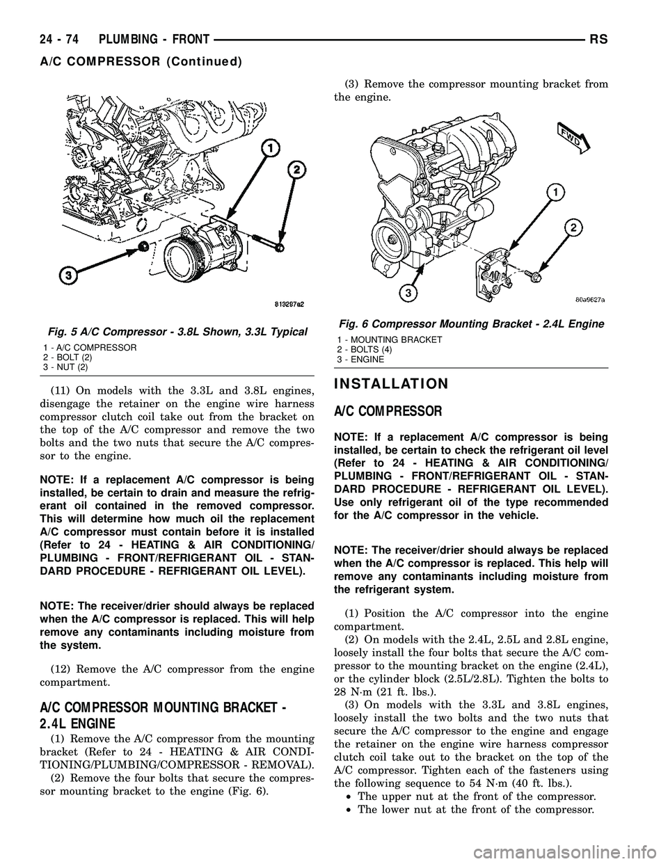
(11) On models with the 3.3L and 3.8L engines,
disengage the retainer on the engine wire harness
compressor clutch coil take out from the bracket on
the top of the A/C compressor and remove the two
bolts and the two nuts that secure the A/C compres-
sor to the engine.
NOTE: If a replacement A/C compressor is being
installed, be certain to drain and measure the refrig-
erant oil contained in the removed compressor.
This will determine how much oil the replacement
A/C compressor must contain before it is installed
(Refer to 24 - HEATING & AIR CONDITIONING/
PLUMBING - FRONT/REFRIGERANT OIL - STAN-
DARD PROCEDURE - REFRIGERANT OIL LEVEL).
NOTE: The receiver/drier should always be replaced
when the A/C compressor is replaced. This will help
remove any contaminants including moisture from
the system.
(12) Remove the A/C compressor from the engine
compartment.
A/C COMPRESSOR MOUNTING BRACKET -
2.4L ENGINE
(1) Remove the A/C compressor from the mounting
bracket (Refer to 24 - HEATING & AIR CONDI-
TIONING/PLUMBING/COMPRESSOR - REMOVAL).
(2) Remove the four bolts that secure the compres-
sor mounting bracket to the engine (Fig. 6).(3) Remove the compressor mounting bracket from
the engine.
INSTALLATION
A/C COMPRESSOR
NOTE: If a replacement A/C compressor is being
installed, be certain to check the refrigerant oil level
(Refer to 24 - HEATING & AIR CONDITIONING/
PLUMBING - FRONT/REFRIGERANT OIL - STAN-
DARD PROCEDURE - REFRIGERANT OIL LEVEL).
Use only refrigerant oil of the type recommended
for the A/C compressor in the vehicle.
NOTE: The receiver/drier should always be replaced
when the A/C compressor is replaced. This help will
remove any contaminants including moisture from
the refrigerant system.
(1) Position the A/C compressor into the engine
compartment.
(2) On models with the 2.4L, 2.5L and 2.8L engine,
loosely install the four bolts that secure the A/C com-
pressor to the mounting bracket on the engine (2.4L),
or the cylinder block (2.5L/2.8L). Tighten the bolts to
28 N´m (21 ft. lbs.).
(3) On models with the 3.3L and 3.8L engines,
loosely install the two bolts and the two nuts that
secure the A/C compressor to the engine and engage
the retainer on the engine wire harness compressor
clutch coil take out to the bracket on the top of the
A/C compressor. Tighten each of the fasteners using
the following sequence to 54 N´m (40 ft. lbs.).
²The upper nut at the front of the compressor.
²The lower nut at the front of the compressor.
Fig. 5 A/C Compressor - 3.8L Shown, 3.3L Typical
1 - A/C COMPRESSOR
2 - BOLT (2)
3 - NUT (2)
Fig. 6 Compressor Mounting Bracket - 2.4L Engine
1 - MOUNTING BRACKET
2 - BOLTS (4)
3 - ENGINE
24 - 74 PLUMBING - FRONTRS
A/C COMPRESSOR (Continued)
Page 2245 of 2339
OPERATION
R-134a refrigerant is not compatible with R-12
refrigerant in an air conditioning system. Even a
small amount of R-12 added to an R-134a refrigerant
system will cause compressor failure, refrigerant oil
sludge or poor air conditioning system performance.
In addition, the PolyAlkylene Glycol (PAG) synthetic
refrigerant oils used in an R-134a refrigerant system
are not compatible with the mineral-based refriger-
ant oils used in an R-12 refrigerant system. R-134a
refrigerant system service ports, service tool couplers
and refrigerant dispensing bottles have all been
designed with unique fittings to ensure that an
R-134a system is not accidentally contaminated with
the wrong refrigerant (R-12). There are also labels
posted in the engine compartment of the vehicle and
on the compressor identifying to service technicians
that the air conditioning system is equipped with
R-134a.
REFRIGERANT OIL
DESCRIPTION
The refrigerant oil used in R-134a refrigerant sys-
tems is a synthetic-based, PolyAlkylene Glycol (PAG),
wax-free lubricant. Mineral-based R-12 refrigerant
oils are not compatible with PAG oils, and should
never be introduced to an R-134a refrigerant system.
There are different PAG oils available, and each con-
tains a different additive package. The compressor
used in this vehicle is designed to use an ND-8 PAG
refrigerant oil. Use only refrigerant oil of this same
type to service the refrigerant system.
OPERATION
After performing any refrigerant recovery or recy-
cling operation, always replenish the refrigerant sys-
tem with the same amount of the recommended
refrigerant oil as was removed. Too little refrigerant
oil can cause compressor damage, and too much can
reduce air conditioning system performance. PAG
refrigerant oil is much more hygroscopic than min-
eral oil, and will absorb any moisture it comes into
contact with, even moisture in the air. The PAG oil
container should always be kept tightly capped until
it is ready to be used. After use, recap the oil con-
tainer immediately to prevent moisture contamina-
tion.
STANDARD PROCEDURE
REFRIGERANT OIL LEVEL
WARNING: REFER TO THE APPLICABLE WARN-
INGS AND CAUTIONS FOR THIS SYSTEM BEFORE
PERFORMING THE FOLLOWING OPERATION (Refer
to 24 - HEATING & AIR CONDITIONING/PLUMBING -
FRONT - WARNING - A/C PLUMBING) and (Refer to
24 - HEATING & AIR CONDITIONING/PLUMBING -
FRONT - CAUTION - A/C PLUMBING).
CAUTION: Use only PAG oils that are designed to
work with R-134a refrigerant and the A/C compres-
sor in the vehicle. Refer to the underhood A/C Sys-
tem Specification Label.
It is important to have the correct amount of lubri-
cant in the A/C refrigerant system to ensure proper
lubrication of the A/C compressor. Too little lubricant
will result in damage to the compressor. Too much
lubricant will reduce the cooling capacity of the A/C
system and consequently result in higher discharge
air temperatures.
The lubricant used in the compressor is polyalka-
lene glycol PAG lubricant. Only the refrigerant lubri-
cant approved for use with this vehicle should be
used to service the system. Do not use any other
lubricant. The lubricant container should be kept
tightly capped until it is ready for use. Refrigerant
lubricant will quickly absorb any moisture it comes
in contact with.
It will not be necessary to check the oil level in the
A/C compressor or to add oil, unless there has been
an oil loss. An oil loss may occur due to a rupture or
leak from a refrigerant line, connector fitting, compo-
nent or component seal. If a leak occurs, add 30 mil-
liliters (1 fluid ounce) of the recommended
refrigerant oil to the refrigerant system after the
repair has been made. Refrigerant oil loss will be evi-
dent at the leak point by the presence of a wet, shiny
surface around the leak.
REFRIGERANT OIL LEVEL CHECK
When an air conditioning system is first assembled
at the factory, all components (except the A/C com-
pressor) are refrigerant oil free. After the refrigerant
system has been charged with (R-134a) refrigerant
and operated, the oil in the A/C compressor is dis-
persed through the lines and components. The A/C
evaporator, A/C condenser, and receiver/drier will
retain a significant amount of oil. Refer to the A/C
Component Refrigerant Oil Capacities table. When a
component is replaced, the specified amount of refrig-
erant oil must be added. When the compressor is
replaced, the amount of oil that is retained in the
24 - 94 PLUMBING - FRONTRS
REFRIGERANT (Continued)
Page 2246 of 2339
rest of the system must be drained from the replace-
ment A/C compressor. The oil capacity of the system,
minus the amount of oil still in the remaining com-
ponents (refer to the oil capacity chart below) can be
measured and poured into the suction port of the A/C
compressor. When a line or component has ruptured
and oil has escaped, the receiver/drier must be
replaced along with the ruptured component.
Example: On this A/C system the front A/C evapo-
rator retains 50 ml. (1.7 oz.). The A/C condenser
retains 50 ml. (1.7 oz.) of oil, and front A/C system oil
capacity is 180 ml. (6.1 oz.).
180 ml. ± 100 ml. = 80 ml. (2.7 oz.).
A/C COMPONENT REFRIGERANT OIL
CAPACITIES
Front A/C Front & Rear
A/C
COMPONENT ml fl oz ml fl oz
Total System Fill 180 6.1 230 7.8
Receiver/Drier 25 0.8 25 0.8
A/C Condenser 50 1.7 50 1.7
Front Evaporator 50 1.7 50 1.7
Rear Evap. (including
underbody lines)N/A N/A 50 1.7
A/C Compressor Drain and measure the oil
from the old A/C compressor
- See text above.
VERIFY REFRIGERANT LUBRICANT LEVEL
(1) Recover the refrigerant from the system.
(2) Disconnect the refrigerant lines from the A/C
compressor. Cap open lines to prevent moisture from
entering the system.
(3) Remove A/C compressor from the vehicle.
(4) From the suction and discharge ports on the
A/C compressor, drain the lubricant from the com-
pressor.
(5) Add the system capacity minus the capacity of
the components that have not been replaced. Refer to
the A/C Component Refrigerant Oil Capacities chart.
Add lubricant through the suction and discharge
ports on the A/C compressor.
(6) Install the A/C compressor and connect the
refrigerant lines. Then evacuate and charge refriger-
ant system.
(7) Most reclaim/recycling equipment will measure
the lubricant being removed. This amount of lubri-
cant should be added back to the system. If a new
A/C compressor is being installed, drain the lubricant
from the used compressor, measure the amount
drained and discard the used lubricant. Drain the
lubricant from the new A/C compressor into a cleancontainer. Return the amount of lubricant measured
from the used compressor, plus the amount reclaimed
from the system back into the new A/C compressor.
Refer to the reclaim/recycling equipment manufactur-
ers instructions.
SERVICE PORT VALVE CORE
DESCRIPTION
A/C SERVICE PORT VALVE CORES
The low side valve is located on the suction line
near the A/C compressor. The low side A/C service
port valve core is a serviceable item. The high side
A/C service port valve core is located on the liquid
line fitting attached to the top of the receiver/drier.
The high side A/C service port valve core is not a sep-
arate serviceable item. If the high side service port
valve core is faulty or damaged, the front section of
the liquid line will require replacement.
REMOVAL
WARNING: REFER TO THE APPLICABLE WARN-
INGS AND CAUTIONS FOR THIS SYSTEM BEFORE
PERFORMING THE FOLLOWING OPERATION (Refer
to 24 - HEATING & AIR CONDITIONING/PLUMBING -
FRONT - WARNING - A/C PLUMBING) and (Refer to
24 - HEATING & AIR CONDITIONING/PLUMBING -
FRONT - CAUTION - A/C PLUMBING).
(1) Recover the refrigerant from the refrigerant
system (Refer to 24 - HEATING & AIR CONDITION-
ING/PLUMBING - FRONT/REFRIGERANT - STAN-
DARD PROCEDURE - REFRIGERANT
RECOVERY).
(2) Using a standard Schrader-type valve core tool,
remove the valve core from the low side A/C service
port located on the suction line.
(3) Install a plug in or tape over the opened low
side A/C service port.
INSTALLATION
(1) Lubricate the low side A/C service port valve
core with clean refrigerant oil prior to installation.
Use only refrigerant oil of the type recommended for
the compressor in the vehicle.
(2) Remove the tape or plug from the A/C service
port located on the suction line near the A/C com-
pressor.
(3) Using a standard Schrader-type valve core tool,
install and tighten the replacement valve core into
the low side A/C service port.
RSPLUMBING - FRONT24-95
REFRIGERANT OIL (Continued)
Page 2252 of 2339

DIAGNOSIS AND TESTING
REAR A/C EXPANSION VALVE
WARNING: REFER TO THE APPLICABLE WARN-
INGS AND CAUTIONS FOR THIS SYSTEM BEFORE
PERFORMING THE FOLLOWING OPERATION.
(Refer to 24 - HEATING & AIR CONDITIONING/
PLUMBING - FRONT - WARNING - A/C PLUMBING)
and (Refer to 24 - HEATING & AIR CONDITIONING/
PLUMBING - FRONT - CAUTION - A/C PLUMBING).
NOTE: The expansion valve should only be tested
following testing of the compressor.
NOTE: Liquid CO
2is required to test the expansion
valve. This material is available from most welding
supply facilities. Liquid CO
2is also available from
companies which service and sell fire extinguish-
ers.
When testing the expansion valve, the work area
and the vehicle temperature must be 21É to 27É C
(70É to 85É F). To test the expansion valve:
(1) Connect a charging station or manifold gauge
set to the refrigerant system service ports. Verify the
refrigerant charge level.
(2) Close all doors, windows and vents to the pas-
senger compartment.
(3) Set the heater-air conditioner controls so that
the compressor is operating, the temperature control
is in the highest temperature position, the mode door
is directing the output to the floor outlets, and the
blower is operating at the highest speed setting.
(4) Start the engine and allow it to idle at 1000
rpm. After the engine has reached normal operating
temperature, allow the passenger compartment to
heat up. This will create the need for maximum
refrigerant flow into the evaporator.
(5) If the refrigerant charge is sufficient, the dis-
charge (high pressure) gauge should read 965 to 1655
kPa (140 to 240 psi). The suction (low pressure)
gauge should read 140 kPa to 207 kPa (20 psi to 30
psi). If OK, go to Step 6. If not OK, replace the faulty
expansion valve.
WARNING: PROTECT THE SKIN AND EYES FROM
EXPOSURE TO LIQUID CO
2. PERSONAL INJURY
CAN RESULT.
(6)
If the suction (low pressure) gauge reads within
the specified range, freeze the expansion valve control
head for 30 seconds using liquid CO
2or another suit-
able super-cold material.Do not spray R-134a or
R-12 refrigerant on the expansion valve controlhead for this test.
The suction (low pressure) gauge
reading should drop by 10 psi. If OK, go to Step 7 If
not OK, replace the faulty expansion valve.
(7) Allow the expansion valve control head to thaw.
The suction (low pressure) gauge reading should sta-
bilize at 140 kPa to 240 kPa (20 psi to 30 psi). If not
OK, replace the faulty expansion valve.
(8) When expansion valve testing is complete, test
the overall air conditioner performance (Refer to 24 -
HEATING & AIR CONDITIONING - DIAGNOSIS
AND TESTING - A/C PERFORMANCE TEST).
Remove all test equipment before returning the vehi-
cle to service.
REMOVAL
WARNING: REFER TO THE APPLICABLE WARN-
INGS AND CAUTIONS FOR THIS SYSTEM BEFORE
PERFORMING THE FOLLOWING OPERATION (Refer
to 24 - HEATING & AIR CONDITIONING/PLUMBING -
FRONT - WARNING - A/C PLUMBING), (Refer to 24 -
HEATING & AIR CONDITIONING/PLUMBING -
FRONT - CAUTION - A/C PLUMBING), and (Refer to
24 - HEATING & AIR CONDITIONING/PLUMBING -
FRONT - WARNING - HEATER PLUMBING).
(1) Remove the rear HVAC housing from the vehi-
cle (Refer to 24 - HEATING & AIR CONDITIONING/
DISTRIBUTION/HVAC HOUSING - REMOVAL).
(2) Carefully remove the foam insulator wrap from
the rear expansion valve.
(3) Remove the rear evaporator line extension from
the expansion valve (Refer to 24 - HEATING & AIR
CONDITIONING/PLUMBING - REAR/EVAPORA-
TOR - REMOVAL - EVAPORATOR LINE EXTEN-
SION).
(4) Remove the two screws that secure the expan-
sion valve to the evaporator tube sealing plate.
(5) Remove the expansion valve from the evapora-
tor tubes.
(6) Remove the seals from the evaporator tube fit-
tings and discard.
(7) Install plugs in, or tape over the opened evap-
orator tube fittings and both expansion valve ports.
INSTALLATION
(1) Remove the tape or plugs from the rear A/C
evaporator tube fittings and both expansion valve
ports.
(2) Lubricate new rubber O-ring seals with clean
refrigerant oil and install them on the rear evapora-
tor tube fittings.
(3) Position the expansion valve onto the evapora-
tor tubes.
(4) Install the two screws that secure the rear A/C
expansion valve to the evaporator tube sealing plate.
Tighten the screws to 11 N´m (97 in. lbs.).
RSPLUMBING - REAR24 - 101
A/C EXPANSION VALVE (Continued)
Page 2275 of 2339
The following is a list of the monitored compo-
nents:
²Catalyst Monitor
²Comprehensive Components
²EGR (if equipped)
²Fuel Control (rich/lean)
²Oxygen Sensor Monitor
²Oxygen Sensor Heater Monitor
²Purge
²Misfire
²Natural Vacuum Leak Detection (NVLD)
COMPREHENSIVE COMPONENTS
Along with the major monitors, OBD II requires
that the diagnostic system monitor any component
that could affect emissions levels. In many cases,
these components were being tested under OBD I.
The OBD I requirements focused mainly on testing
emissions-related components for electrical opens and
shorts.
However, OBD II also requires that inputs from
powertrain components to the PCM be tested for
rationality, and that outputs to powertrain compo-
nents from the PCM be tested forfunctionality.
Methods for monitoring the various Comprehensive
Component monitoring include:
(1) Circuit Continuity
²Open
²Shorted high
²Shorted to ground
(2) Rationality or Proper Functioning
²Inputs tested for rationality
²Outputs tested for functionality
NOTE: Comprehensive component monitors are
continuous. Therefore, enabling conditions do not
apply. All will set a DTC and illuminate the MIL in 1-
trip.
Input RationalityÐWhile input signals to the
PCM are constantly being monitored for electrical
opens and shorts, they are also tested for rationality.
This means that the input signal is compared against
other inputs and information to see if it makes sense
under the current conditions.
PCM sensor inputs that are checked for rationality
include:
²Manifold Absolute Pressure (MAP) Sensor
²Oxygen Sensor (O2S) (slow response)
²Engine Coolant Temperature (ECT) Sensor
²Camshaft Position (CMP) Sensor
²Vehicle Speed Sensor
²Crankshaft Position (CKP) Sensor
²Intake Air Temperature (IAT) Sensor
²Throttle Position (TPS) Sensor
²Ambient/Battery Temperature Sensors
²Power Steering Switch²Oxygen Sensor Heater
²Engine Controller
²Brake Switch
²Natural Vacuum Leak Detection (NVLD)
²P/N Switch
²Trans Controls
Output FunctionalityÐPCM outputs are tested
for functionality in addition to testing for opens and
shorts. When the PCM provides a voltage to an out-
put component, it can verify that the command was
carried out by monitoring specific input signals for
expected changes. For example, when the PCM com-
mands the Idle Air Control (IAC) Motor to a specific
position under certain operating conditions, it expects
to see a specific (target) idle speed (RPM). If it does
not, it stores a DTC.
PCM outputs monitored for functionality include:
²Fuel Injectors
²Ignition Coils
²Torque Converter Clutch Solenoid
²Idle Air Control
²Purge Solenoid
²EGR Solenoid
²Radiator Fan Control
²Trans Controls
OXYGEN SENSOR (O2S) MONITOR
DESCRIPTIONÐEffective control of exhaust
emissions is achieved by an oxygen feedback system.
The most important element of the feedback system
is the O2S. The O2S is located in the exhaust path.
Once it reaches operating temperature 300É to 350ÉC
(572É to 662ÉF), the sensor generates a voltage that
is inversely proportional to the amount of oxygen in
the exhaust. When there is a large amount of oxygen
in the exhaust caused by a lean condition, misfire or
exhaust leak, the sensor produces a low voltage,
below 450 mV. When the oxygen content is lower,
caused by a rich condition, the sensor produces a
higher voltage, above 450mV.
The information obtained by the sensor is used to
calculate the fuel injector pulse width. The PCM is
programmed to maintain the optimum air/fuel ratio.
At this mixture ratio, the catalyst works best to
remove hydrocarbons (HC), carbon monoxide (CO)
and nitrous oxide (NOx) from the exhaust.
The O2S is also the main sensing element for the
EGR, Catalyst and Fuel Monitors, and purge.
The O2S may fail in any or all of the following
manners:
²Slow response rate (Big Slope)
²Reduced output voltage (Half Cycle)
²Heater Performance
Slow Response Rate (Big Slope)ÐResponse rate
is the time required for the sensor to switch from
lean to rich signal output once it is exposed to a
25 - 2 EMISSIONS CONTROLRS
EMISSIONS CONTROL (Continued)