2005 CHRYSLER CARAVAN oil level
[x] Cancel search: oil levelPage 1316 of 2339

OIL
STANDARD PROCEDURE
STANDARD PROCEDURE - ENGINE OIL AND
FILTER CHANGE
Change engine oil at mileage and time intervals
described in the Maintenance Schedule. (Refer to
LUBRICATION & MAINTENANCE/MAINTE-
NANCE SCHEDULES - DESCRIPTION)
WARNING: NEW OR USED ENGINE OIL CAN BE
IRRITATING TO THE SKIN. AVOID PROLONGED OR
REPEATED SKIN CONTACT WITH ENGINE OIL.
CONTAMINANTS IN USED ENGINE OIL, CAUSED BY
INTERNAL COMBUSTION, CAN BE HAZARDOUS TO
YOUR HEALTH. THOROUGHLY WASH EXPOSED
SKIN WITH SOAP AND WATER. DO NOT WASH
SKIN WITH GASOLINE, DIESEL FUEL, THINNER, OR
SOLVENTS, HEALTH PROBLEMS CAN RESULT. DO
NOT POLLUTE, DISPOSE OF USED ENGINE OIL
PROPERLY. CONTACT YOUR DEALER OR GOVERN-
MENT AGENCY FOR LOCATION OF COLLECTION
CENTER IN YOUR AREA.Run engine until achieving normal operating tem-
perature.
(1) Position the vehicle on a level surface and turn
engine off.
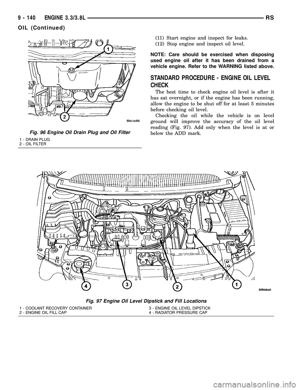
(2) Open hood, remove oil fill cap (Fig. 97).
(3) Hoist and support vehicle on safety stands.
Refer to Hoisting and Jacking Recommendations.
(Refer to LUBRICATION & MAINTENANCE/HOIST-
ING - STANDARD PROCEDURE)
(4) Place a suitable drain pan under crankcase
drain (Fig. 96).
(5) Remove drain plug from crankcase (Fig. 96)
and allow oil to drain into pan. Inspect drain plug
threads for stretching or other damage. Replace
drain plug and gasket if damaged.
(6) Remove oil filter. (Refer to 9 - ENGINE/LUBRI-
CATION/OIL FILTER - REMOVAL)
(7) Install and tighten drain plug in crankcase.
(8) Install new oil filter. (Refer to 9 - ENGINE/LU-
BRICATION/OIL FILTER - INSTALLATION)
(9) Lower vehicle and fill crankcase with specified
type and amount of engine oil. (Refer to LUBRICA-
TION & MAINTENANCE/FLUID TYPES -
DESCRIPTION)
(10) Install oil fill cap.
Fig. 95 Engine Oiling System
1 - OIL SUPPLY FOR BALL SOCKET THROUGH PUSH ROD 7 - OUTER ROTOR
2 - OIL SUPPLY PASSAGE FROM SHAFT TO ROCKER ARM 8 - INNER ROTOR
3 - ROCKER SHAFT 9 - RELIEF VALVE
4 - OIL FLOWS TO ONLY ONE PEDASTAL ON EACH HEAD; THIRD
FROM REAR ON RIGHT HEAD, THIRD FROM FRONT ON LEFT
HEAD10 - OIL PAN
5 - ROCKER SHAFT TOWER 11 - OIL SCREEN
6 - CRANKSHAFT 12 - OIL PUMP CASE
RSENGINE 3.3/3.8L9 - 139
LUBRICATION (Continued)
Page 1317 of 2339
(11) Start engine and inspect for leaks.
(12) Stop engine and inspect oil level.
NOTE: Care should be exercised when disposing
used engine oil after it has been drained from a
vehicle engine. Refer to the WARNING listed above.
STANDARD PROCEDURE - ENGINE OIL LEVEL
CHECK
The best time to check engine oil level is after it
has sat overnight, or if the engine has been running,
allow the engine to be shut off for at least 5 minutes
before checking oil level.
Checking the oil while the vehicle is on level
ground will improve the accuracy of the oil level
reading (Fig. 97). Add only when the level is at or
below the ADD mark.
Fig. 97 Engine Oil Level Dipstick and Fill Locations
1 - COOLANT RECOVERY CONTAINER 3 - ENGINE OIL LEVEL DIPSTICK
2 - ENGINE OIL FILL CAP 4 - RADIATOR PRESSURE CAP
Fig. 96 Engine Oil Drain Plug and Oil Filter
1 - DRAIN PLUG
2 - OIL FILTER
9 - 140 ENGINE 3.3/3.8LRS
OIL (Continued)
Page 1319 of 2339
OIL FILTER ADAPTER
REMOVAL
(1) Raise vehicle on hoist.
(2) Remove the oil filter.
(3) Disconnect oil pressure switch electrical con-
nector.
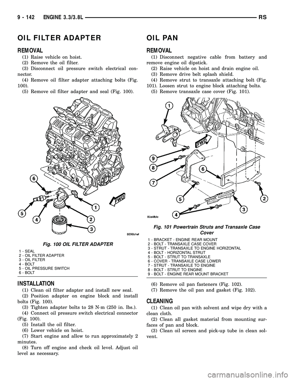
(4) Remove oil filter adapter attaching bolts (Fig.
100).
(5) Remove oil filter adapter and seal (Fig. 100).
INSTALLATION
(1) Clean oil filter adapter and install new seal.
(2) Position adapter on engine block and install
bolts (Fig. 100).
(3) Tighten adapter bolts to 28 N´m (250 in. lbs.).
(4) Connect oil pressure switch electrical connector
(Fig. 100).
(5) Install the oil filter.
(6) Lower vehicle on hoist.
(7) Start engine and allow to run approximately 2
minutes.
(8) Turn off engine and check oil level. Adjust oil
level as necessary.
OIL PAN
REMOVAL
(1) Disconnect negative cable from battery and
remove engine oil dipstick.
(2) Raise vehicle on hoist and drain engine oil.
(3) Remove drive belt splash shield.
(4) Remove strut to transaxle attaching bolt (Fig.
101). Loosen strut to engine block attaching bolts.
(5) Remove transaxle case cover (Fig. 101).
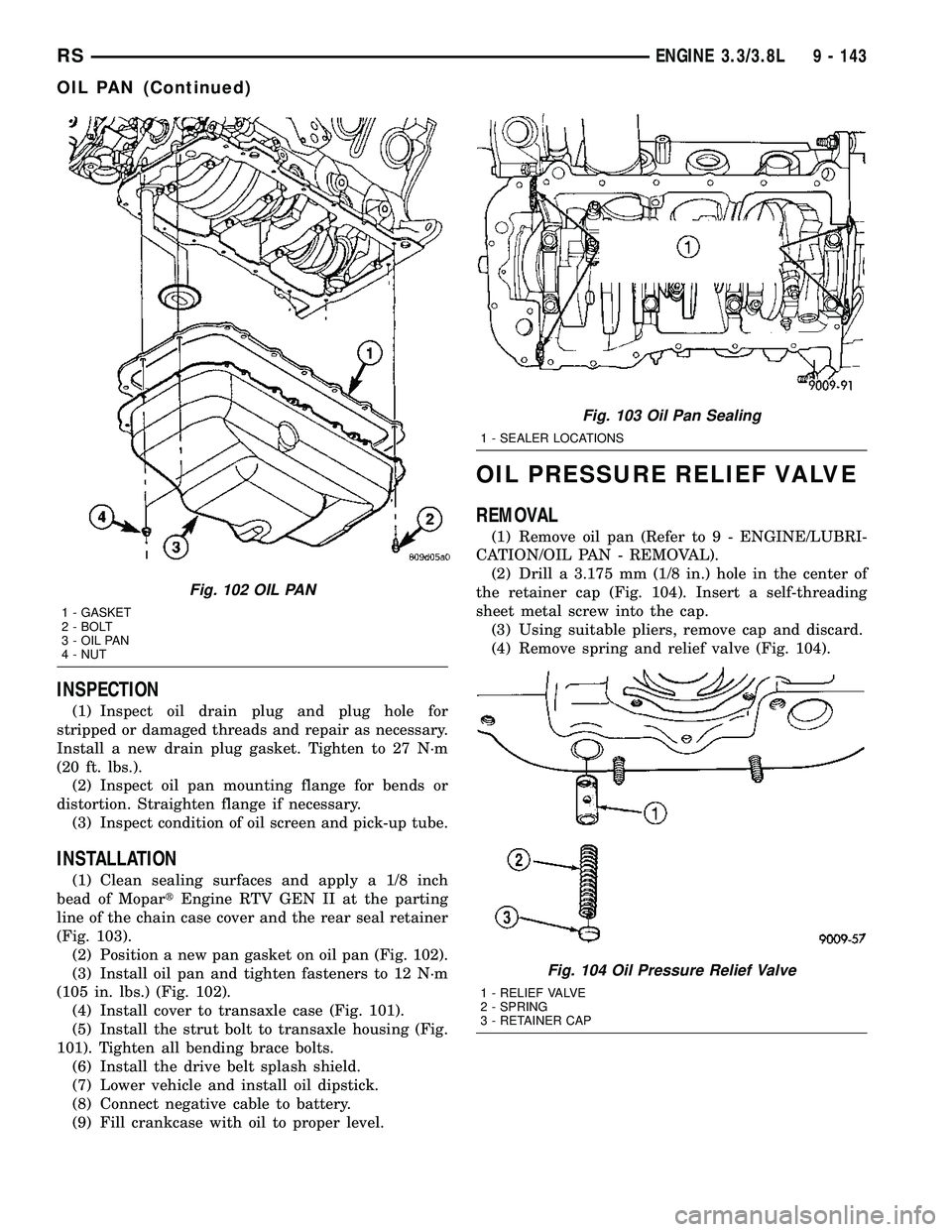
(6) Remove oil pan fasteners (Fig. 102).
(7) Remove the oil pan and gasket (Fig. 102).
CLEANING
(1) Clean oil pan with solvent and wipe dry with a
clean cloth.
(2) Clean all gasket material from mounting sur-
faces of pan and block.
(3) Clean oil screen and pick-up tube in clean sol-
vent.
Fig. 100 OIL FILTER ADAPTER
1 - SEAL
2 - OIL FILTER ADAPTER
3 - OIL FILTER
4 - BOLT
5 - OIL PRESSURE SWITCH
6 - BOLT
Fig. 101 Powertrain Struts and Transaxle Case
Cover
1 - BRACKET - ENGINE REAR MOUNT
2 - BOLT - TRANSAXLE CASE COVER
3 - STRUT - TRANSAXLE TO ENGINE HORIZONTAL
4 - BOLT - HORIZONTAL STRUT
5 - BOLT - STRUT TO TRANSAXLE
6 - COVER - TRANSAXLE CASE LOWER
7 - STRUT - TRANSAXLE TO ENGINE
8 - BOLT - STRUT TO ENGINE
9 - BOLT - ENGINE REAR MOUNT BRACKET
9 - 142 ENGINE 3.3/3.8LRS
Page 1320 of 2339
INSPECTION
(1) Inspect oil drain plug and plug hole for
stripped or damaged threads and repair as necessary.
Install a new drain plug gasket. Tighten to 27 N´m
(20 ft. lbs.).
(2) Inspect oil pan mounting flange for bends or
distortion. Straighten flange if necessary.
(3) Inspect condition of oil screen and pick-up tube.
INSTALLATION
(1) Clean sealing surfaces and apply a 1/8 inch
bead of MopartEngine RTV GEN II at the parting
line of the chain case cover and the rear seal retainer
(Fig. 103).
(2) Position a new pan gasket on oil pan (Fig. 102).
(3) Install oil pan and tighten fasteners to 12 N´m
(105 in. lbs.) (Fig. 102).
(4) Install cover to transaxle case (Fig. 101).
(5) Install the strut bolt to transaxle housing (Fig.
101). Tighten all bending brace bolts.
(6) Install the drive belt splash shield.
(7) Lower vehicle and install oil dipstick.
(8) Connect negative cable to battery.
(9) Fill crankcase with oil to proper level.
OIL PRESSURE RELIEF VALVE
REMOVAL
(1) Remove oil pan (Refer to 9 - ENGINE/LUBRI-
CATION/OIL PAN - REMOVAL).
(2) Drill a 3.175 mm (1/8 in.) hole in the center of
the retainer cap (Fig. 104). Insert a self-threading
sheet metal screw into the cap.
(3) Using suitable pliers, remove cap and discard.
(4) Remove spring and relief valve (Fig. 104).
Fig. 102 OIL PAN
1 - GASKET
2 - BOLT
3 - OIL PAN
4 - NUT
Fig. 103 Oil Pan Sealing
1 - SEALER LOCATIONS
Fig. 104 Oil Pressure Relief Valve
1 - RELIEF VALVE
2 - SPRING
3 - RETAINER CAP
RSENGINE 3.3/3.8L9 - 143
OIL PAN (Continued)
Page 1321 of 2339
INSTALLATION
(1) Clean relief valve, spring and bore.
NOTE: Lubricate relief valve with clean engine oil
before installing.
(2) Install relief valve and spring into housing.
(3) Install new retainer cap until flush with seal-
ing surface.
(4) Install oil pan (Refer to 9 - ENGINE/LUBRI-
CATION/OIL PAN - INSTALLATION).
(5) Fill crankcase with proper oil to correct level.
OIL PRESSURE SWITCH
DESCRIPTION
The engine oil pressure switch is located on the
lower left front side of the engine. It screws into the
oil filter adapter. The normally closed switch provides
an input through a single wire to the low pressure
indicator light on the instrument cluster.
OPERATION
The oil pressure switch provides a ground for the
instrument cluster low oil pressure indicator light.
The switch receives oil pressure input from the
engine main oil gallery. When engine oil pressure is
greater than 27.5 Kpa (4 psi), the switch contacts
open, providing a open circuit to the low pressure
indicator light. For wiring circuits and diagnostic
information, (Refer to Appropriate Wiring/Diagnostic
Information).
REMOVAL
(1) Raise vehicle on hoist.
(2) Disconnect electrical connector from switch.
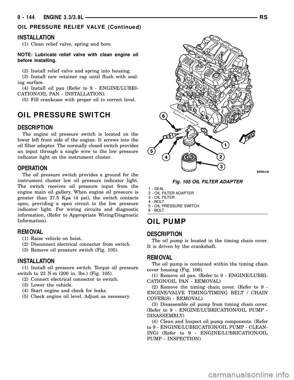
(3) Remove oil pressure switch (Fig. 105).
INSTALLATION
(1) Install oil pressure switch. Torque oil pressure
switch to 23 N´m (200 in. lbs.) (Fig. 105).
(2) Connect electrical connector to switch.
(3) Lower the vehicle.
(4) Start engine and check for leaks.
(5) Check engine oil level. Adjust as necessary.
OIL PUMP
DESCRIPTION
The oil pump is located in the timing chain cover.
It is driven by the crankshaft.
REMOVAL
The oil pump is contained within the timing chain
cover housing (Fig. 106).
(1) Remove oil pan. (Refer to 9 - ENGINE/LUBRI-
CATION/OIL PAN - REMOVAL)
(2) Remove the timing chain cover. (Refer to 9 -
ENGINE/VALVE TIMING/TIMING BELT / CHAIN
COVER(S) - REMOVAL)
(3) Disassemble oil pump from timing chain cover.
(Refer to 9 - ENGINE/LUBRICATION/OIL PUMP -
DISASSEMBLY)
(4) Clean and Inspect oil pump components. (Refer
to 9 - ENGINE/LUBRICATION/OIL PUMP - CLEAN-
ING) (Refer to 9 - ENGINE/LUBRICATION/OIL
PUMP - INSPECTION)
Fig. 105 OIL FILTER ADAPTER
1 - SEAL
2 - OIL FILTER ADAPTER
3 - OIL FILTER
4 - BOLT
5 - OIL PRESSURE SWITCH
6 - BOLT
9 - 144 ENGINE 3.3/3.8LRS
OIL PRESSURE RELIEF VALVE (Continued)
Page 1336 of 2339
(17) Install accessory drive belt. (Refer to 7 -
COOLING/ACCESSORY DRIVE/DRIVE BELTS -
INSTALLATION)
(18) Install oil pump pick-up tube with new
O-ring. Tighten attaching bolt to 28 N´m (250 in.
lbs.).
(19) Install oil pan. (Refer to 9 - ENGINE/LUBRI-
CATION/OIL PAN - INSTALLATION)
(20) Install inner splash shield and right front
wheel.
(21) Fill crankcase with engine oil to proper level.
(22) Fill cooling system. (Refer to 7 - COOLING -
STANDARD PROCEDURE)
(23) Connect negative cable to battery.
TIMING CHAIN AND
SPROCKETS
REMOVAL
REMOVAL - TIMING CHAIN AND CAMSHAFT
SPROCKET
(1) Disconnect negative cable from battery.
(2) Remove the timing chain cover. (Refer to 9 -
ENGINE/VALVE TIMING/TIMING BELT / CHAIN
COVER(S) - REMOVAL)
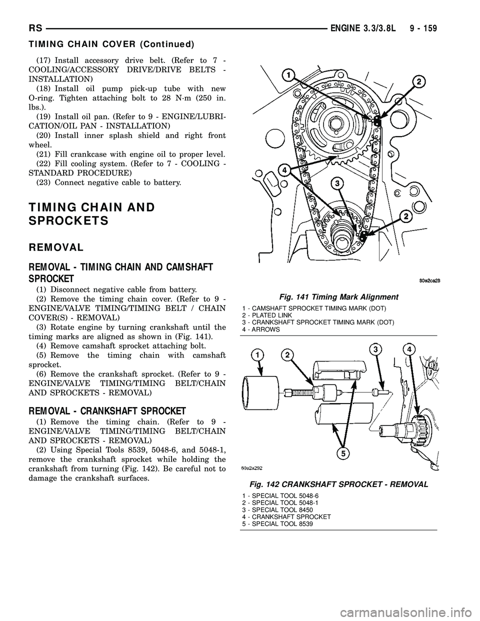
(3) Rotate engine by turning crankshaft until the
timing marks are aligned as shown in (Fig. 141).
(4) Remove camshaft sprocket attaching bolt.
(5) Remove the timing chain with camshaft
sprocket.
(6) Remove the crankshaft sprocket. (Refer to 9 -
ENGINE/VALVE TIMING/TIMING BELT/CHAIN
AND SPROCKETS - REMOVAL)
REMOVAL - CRANKSHAFT SPROCKET
(1) Remove the timing chain. (Refer to 9 -
ENGINE/VALVE TIMING/TIMING BELT/CHAIN
AND SPROCKETS - REMOVAL)
(2) Using Special Tools 8539, 5048-6, and 5048-1,
remove the crankshaft sprocket while holding the
crankshaft from turning (Fig. 142). Be careful not to
damage the crankshaft surfaces.
Fig. 141 Timing Mark Alignment
1 - CAMSHAFT SPROCKET TIMING MARK (DOT)
2 - PLATED LINK
3 - CRANKSHAFT SPROCKET TIMING MARK (DOT)
4 - ARROWS
Fig. 142 CRANKSHAFT SPROCKET - REMOVAL
1 - SPECIAL TOOL 5048-6
2 - SPECIAL TOOL 5048-1
3 - SPECIAL TOOL 8450
4 - CRANKSHAFT SPROCKET
5 - SPECIAL TOOL 8539
RSENGINE 3.3/3.8L9 - 159
TIMING CHAIN COVER (Continued)
Page 1373 of 2339
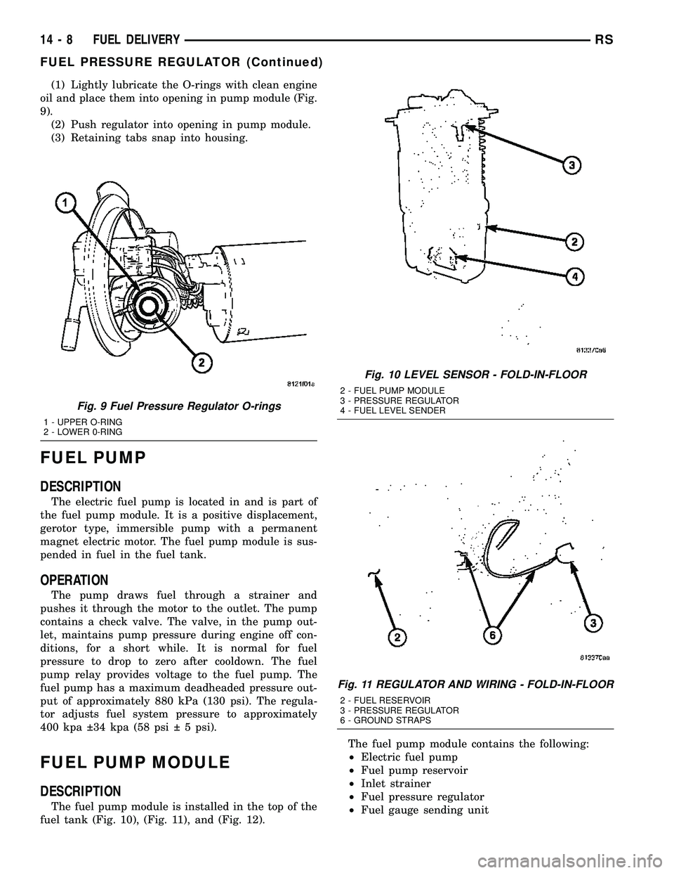
(1) Lightly lubricate the O-rings with clean engine
oil and place them into opening in pump module (Fig.
9).
(2) Push regulator into opening in pump module.
(3) Retaining tabs snap into housing.
FUEL PUMP
DESCRIPTION
The electric fuel pump is located in and is part of
the fuel pump module. It is a positive displacement,
gerotor type, immersible pump with a permanent
magnet electric motor. The fuel pump module is sus-
pended in fuel in the fuel tank.
OPERATION
The pump draws fuel through a strainer and
pushes it through the motor to the outlet. The pump
contains a check valve. The valve, in the pump out-
let, maintains pump pressure during engine off con-
ditions, for a short while. It is normal for fuel
pressure to drop to zero after cooldown. The fuel
pump relay provides voltage to the fuel pump. The
fuel pump has a maximum deadheaded pressure out-
put of approximately 880 kPa (130 psi). The regula-
tor adjusts fuel system pressure to approximately
400 kpa 34 kpa (58 psi 5 psi).
FUEL PUMP MODULE
DESCRIPTION
The fuel pump module is installed in the top of the
fuel tank (Fig. 10), (Fig. 11), and (Fig. 12).The fuel pump module contains the following:
²Electric fuel pump
²Fuel pump reservoir
²Inlet strainer
²Fuel pressure regulator
²Fuel gauge sending unit
Fig. 9 Fuel Pressure Regulator O-rings
1 - UPPER O-RING
2 - LOWER 0-RING
Fig. 10 LEVEL SENSOR - FOLD-IN-FLOOR
2 - FUEL PUMP MODULE
3 - PRESSURE REGULATOR
4 - FUEL LEVEL SENDER
Fig. 11 REGULATOR AND WIRING - FOLD-IN-FLOOR
2 - FUEL RESERVOIR
3 - PRESSURE REGULATOR
6 - GROUND STRAPS
14 - 8 FUEL DELIVERYRS
FUEL PRESSURE REGULATOR (Continued)
Page 1433 of 2339
GEAR
TABLE OF CONTENTS
page page
GEAR
DESCRIPTION.........................26
OPERATION...........................26
WARNING
WARNINGS AND CAUTIONS.............26
REMOVAL
REMOVAL - LHD GEAR.................26
REMOVAL - RHD GEAR................29INSTALLATION
INSTALLATION - LHD GEAR.............31
INSTALLATION - RHD GEAR.............33
SPECIAL TOOLS
POWER STEERING GEAR..............34
OUTER TIE ROD
REMOVAL.............................34
INSTALLATION.........................35
GEAR
DESCRIPTION
This vehicle is equipped with a rack and pinion
power steering gear (Fig. 1). It is mounted to the
underside of the front suspension cradle/crossmem-
ber.
The steering column is attached to the gear
through the use of an intermediate shaft and cou-
plers. The outer ends of the power steering gear's
outer tie rods connect to the steering knuckles.
NOTE: The power steering gear should NOT be ser-
viced or adjusted unless DaimlerChrysler Corpora-
tion authorizes. If a malfunction or oil leak occurs,
the complete steering gear should be replaced.
Only the outer tie rods may be replaced separately
from the rest of the gear.
OPERATION
Turning of the steering wheel is converted into lin-
ear (side-to-side) travel through the meshing of the
helical pinion teeth with the rack teeth in the steer-
ing gear. This travel pushes and pulls the tie rods to
change the direction of the vehicle's front wheels.
Power assist steering provided by the power steer-
ing pump is controlled by an open center, rotary type
control valve which directs oil from the pump to
either side of the integral rack piston upon demand.
Road feel is controlled by the diameter of a torsion
bar which initially steers the vehicle. As required
steering effort increases, as in a turn, the torsion bar
twists, causing relative rotary motion between the
rotary valve body and the valve spool. This move-
ment directs oil behind the integral rack piston
which, in turn, builds hydraulic pressure and assists
in the turning effort.Manual steering control of the vehicle can be main-
tained if power steering assist is lost. However,
under this condition, steering effort is significantly
increased.
WARNING
WARNINGS AND CAUTIONS
WARNING: POWER STEERING FLUID, ENGINE
PARTS AND EXHAUST SYSTEM MAY BE
EXTREMELY HOT IF ENGINE HAS BEEN RUNNING.
DO NOT START ENGINE WITH ANY LOOSE OR DIS-
CONNECTED HOSES. DO NOT ALLOW HOSES TO
TOUCH HOT EXHAUST MANIFOLD OR CATALYST.
WARNING: FLUID LEVEL SHOULD BE CHECKED
WITH THE ENGINE OFF TO PREVENT PERSONAL
INJURY FROM MOVING PARTS.
CAUTION: When the system is open, cap all open
ends of the hoses, power steering pump fittings or
power steering gear ports to prevent entry of for-
eign material into the components.
REMOVAL
REMOVAL - LHD GEAR
(1) Remove cap from power steering fluid reser-
voir.
(2) Using a siphon pump, remove as much fluid as
possible from the power steering fluid reservoir.Use
care not to damage the filter mesh below the
fluid surface.
19 - 26 GEARRS