2005 CHRYSLER CARAVAN oil level
[x] Cancel search: oil levelPage 1254 of 2339
INSPECTION..........................115
HYDRAULIC LIFTERS (CAM IN BLOCK)
DESCRIPTION........................116
DIAGNOSIS AND TESTING - HYDRAULIC
LIFTERS...........................116
REMOVAL............................117
INSTALLATION........................117
CAMSHAFT & BEARINGS (IN BLOCK)
DESCRIPTION........................118
OPERATION..........................118
REMOVAL............................118
INSPECTION..........................118
INSTALLATION........................118
PISTON & CONNECTING ROD
DESCRIPTION........................119
STANDARD PROCEDURE
STANDARD PROCEDURE - FITTING
CONNECTING RODS..................119
STANDARD PROCEDURE - FITTING
PISTONS...........................120
REMOVAL............................120
INSTALLATION........................121
CONNECTING ROD BEARINGS
STANDARD PROCEDURE - MEASURING
CONNECTING ROD BEARING
CLEARANCE........................123
PISTON RINGS
STANDARD PROCEDURE - PISTON RING
FITTING............................124
REMOVAL............................124
INSTALLATION........................124
CRANKSHAFT MAIN BEARINGS
STANDARD PROCEDURE - MAIN BEARING
FITTING............................125
REMOVAL - CRANKSHAFT MAIN BEARINGS . 127
INSTALLATION - CRANKSHAFT MAIN
BEARINGS..........................127
CRANKSHAFT
DESCRIPTION
DESCRIPTION - 3.3L..................128
DESCRIPTION - 3.8L..................128
STANDARD PROCEDURE - MEASURING
CRANKSHAFT END PLAY..............128
REMOVAL............................128
INSTALLATION........................129
CRANKSHAFT OIL SEAL - FRONT
REMOVAL............................130
INSTALLATION........................130
CRANKSHAFT OIL SEAL - REAR
REMOVAL............................131
INSTALLATION........................131
CRANKSHAFT REAR OIL SEAL RETAINER
REMOVAL............................132
INSTALLATION........................132
VIBRATION DAMPER
REMOVAL............................132
INSTALLATION........................132FLEX PLATE
REMOVAL............................133
INSTALLATION........................133
ENGINE MOUNTING
DESCRIPTION........................134
FRONT MOUNT
REMOVAL............................134
INSTALLATION........................134
LEFT MOUNT
REMOVAL............................136
INSTALLATION........................136
REAR MOUNT
REMOVAL............................136
INSTALLATION........................137
RIGHT MOUNT
REMOVAL............................138
INSTALLATION........................138
LUBRICATION
DESCRIPTION........................138
OPERATION..........................138
DIAGNOSIS AND TESTING - ENGINE OIL
PRESSURE.........................138
OIL
STANDARD PROCEDURE
STANDARD PROCEDURE - ENGINE OIL
AND FILTER CHANGE.................139
STANDARD PROCEDURE - ENGINE OIL
LEVEL CHECK.......................140
OIL COOLER & LINES
DESCRIPTION........................141
OPERATION..........................141
REMOVAL............................141
INSTALLATION........................141
OIL FILTER
REMOVAL............................141
INSTALLATION........................141
OIL FILTER ADAPTER
REMOVAL............................142
INSTALLATION........................142
OIL PAN
REMOVAL............................142
CLEANING...........................142
INSPECTION.........................143
INSTALLATION........................143
OIL PRESSURE RELIEF VALVE
REMOVAL............................143
INSTALLATION........................144
OIL PRESSURE SWITCH
DESCRIPTION........................144
OPERATION..........................144
REMOVAL............................144
INSTALLATION........................144
OIL PUMP
DESCRIPTION........................144
REMOVAL............................144
DISASSEMBLY........................145
CLEANING...........................145
RSENGINE 3.3/3.8L9-77
Page 1259 of 2339
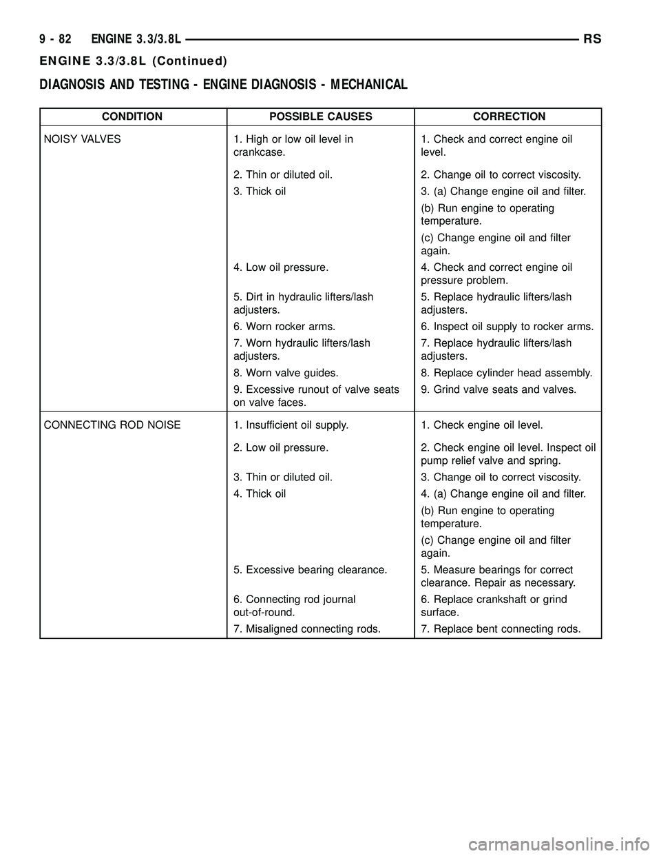
DIAGNOSIS AND TESTING - ENGINE DIAGNOSIS - MECHANICAL
CONDITION POSSIBLE CAUSES CORRECTION
NOISY VALVES 1. High or low oil level in
crankcase.1. Check and correct engine oil
level.
2. Thin or diluted oil. 2. Change oil to correct viscosity.
3. Thick oil 3. (a) Change engine oil and filter.
(b) Run engine to operating
temperature.
(c) Change engine oil and filter
again.
4. Low oil pressure. 4. Check and correct engine oil
pressure problem.
5. Dirt in hydraulic lifters/lash
adjusters.5. Replace hydraulic lifters/lash
adjusters.
6. Worn rocker arms. 6. Inspect oil supply to rocker arms.
7. Worn hydraulic lifters/lash
adjusters.7. Replace hydraulic lifters/lash
adjusters.
8. Worn valve guides. 8. Replace cylinder head assembly.
9. Excessive runout of valve seats
on valve faces.9. Grind valve seats and valves.
CONNECTING ROD NOISE 1. Insufficient oil supply. 1. Check engine oil level.
2. Low oil pressure. 2. Check engine oil level. Inspect oil
pump relief valve and spring.
3. Thin or diluted oil. 3. Change oil to correct viscosity.
4. Thick oil 4. (a) Change engine oil and filter.
(b) Run engine to operating
temperature.
(c) Change engine oil and filter
again.
5. Excessive bearing clearance. 5. Measure bearings for correct
clearance. Repair as necessary.
6. Connecting rod journal
out-of-round.6. Replace crankshaft or grind
surface.
7. Misaligned connecting rods. 7. Replace bent connecting rods.
9 - 82 ENGINE 3.3/3.8LRS
ENGINE 3.3/3.8L (Continued)
Page 1260 of 2339
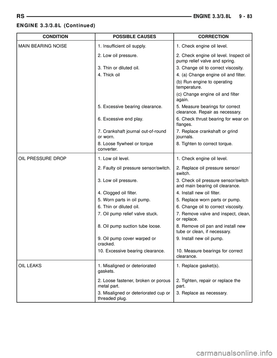
CONDITION POSSIBLE CAUSES CORRECTION
MAIN BEARING NOISE 1. Insufficient oil supply. 1. Check engine oil level.
2. Low oil pressure. 2. Check engine oil level. Inspect oil
pump relief valve and spring.
3. Thin or diluted oil. 3. Change oil to correct viscosity.
4. Thick oil 4. (a) Change engine oil and filter.
(b) Run engine to operating
temperature.
(c) Change engine oil and filter
again.
5. Excessive bearing clearance. 5. Measure bearings for correct
clearance. Repair as necessary.
6. Excessive end play. 6. Check thrust bearing for wear on
flanges.
7. Crankshaft journal out-of-round
or worn.7. Replace crankshaft or grind
journals.
8. Loose flywheel or torque
converter.8. Tighten to correct torque.
OIL PRESSURE DROP 1. Low oil level. 1. Check engine oil level.
2. Faulty oil pressure sensor/switch. 2. Replace oil pressure sensor/
switch.
3. Low oil pressure. 3. Check oil pressure sensor/switch
and main bearing oil clearance.
4. Clogged oil filter. 4. Install new oil filter.
5. Worn parts in oil pump. 5. Replace worn parts or pump.
6. Thin or diluted oil. 6. Change oil to correct viscosity.
7. Oil pump relief valve stuck. 7. Remove valve and inspect, clean,
or replace.
8. Oil pump suction tube loose. 8. Remove oil pan and install new
tube or clean, if necessary.
9. Oil pump cover warped or
cracked.9. Install new oil pump.
10. Excessive bearing clearance. 10. Measure bearings for correct
clearance.
OIL LEAKS 1. Misaligned or deteriorated
gaskets.1. Replace gasket(s).
2. Loose fastener, broken or porous
metal part.2. Tighten, repair or replace the
part.
3. Misaligned or deteriorated cup or
threaded plug.3. Replace as necessary.
RSENGINE 3.3/3.8L9-83
ENGINE 3.3/3.8L (Continued)
Page 1262 of 2339
(3) Remove torque converter or clutch housing
cover and inspect rear of block for evidence of oil.
Use a black light to check for the oil leak. If a leak is
present in this area, remove transmission for further
inspection.
(a) Circular spray pattern generally indicates
seal leakage or crankshaft damage.
(b) Where leakage tends to run straight down,
possible causes are a porous block, oil gallery cup
plug, bedplate to cylinder block mating surfaces
and seal bore. See proper repair procedures for
these items.
(4) If no leaks are detected, pressurize the crank-
case as previously described.
CAUTION: Do not exceed 20.6 kPa (3 psi).
(5) If the leak is not detected, very slowly turn the
crankshaft and watch for leakage. If a leak is
detected between the crankshaft and seal while
slowly turning the crankshaft, it is possible the
crankshaft seal surface is damaged. The seal area on
the crankshaft could have minor nicks or scratches
that can be polished out with emery cloth.
CAUTION: Use extreme caution when crankshaft
polishing is necessary to remove minor nicks and
scratches. The crankshaft seal flange is especially
machined to complement the function of the rear oil
seal.
(6) For bubbles that remain steady with shaft
rotation, no further inspection can be done until dis-
assembled.
(7) After the oil leak root cause and appropriate
corrective action have been identified, replace compo-
nent(s) as necessary.
DIAGNOSIS AND TESTING - CYLINDER
COMPRESSION PRESSURE TEST
The results of a cylinder compression pressure test
can be utilized to diagnose several engine malfunc-
tions.
Ensure the battery is completely charged and the
engine starter motor is in good operating condition.
Otherwise the indicated compression pressures may
not be valid for diagnosis purposes.
(1) Check engine oil level and add oil if necessary.
(2) Drive the vehicle until engine reaches normal
operating temperature. Select a route free from traf-
fic and other forms of congestion, observe all traffic
laws, and accelerate through the gears several times
briskly.
(3) Remove all spark plugs from engine. As spark
plugs are being removed, check electrodes for abnor-
mal firing indicators fouled, hot, oily, etc. Record cyl-
inder number of spark plug for future reference.(4) Remove the Auto Shutdown (ASD) relay from
the PDC.
(5) Be sure throttle blade is fully open during the
compression check.
(6) Insert compression gauge adaptor Special Tool
8116 or the equivalent, into the #1 spark plug hole in
cylinder head. Connect the 0±500 psi (Blue) pressure
transducer (Special Tool CH7059) with cable adap-
tors to the DRBIIIt. For Special Tool identification,
(Refer to 9 - ENGINE - SPECIAL TOOLS).
(7) Crank engine until maximum pressure is
reached on gauge. Record this pressure as #1 cylin-
der pressure.
(8) Repeat the previous step for all remaining cyl-
inders.
(9) Compression should not be less than 689 kPa
(100 psi) and not vary more than 25 percent from cyl-
inder to cylinder.
(10) If one or more cylinders have abnormally low
compression pressures, repeat the compression test.
(11) If the same cylinder or cylinders repeat an
abnormally low reading on the second compression
test, it could indicate the existence of a problem in
the cylinder in question.The recommended com-
pression pressures are to be used only as a
guide to diagnosing engine problems. An engine
should not be disassembled to determine the
cause of low compression unless some malfunc-
tion is present.
DIAGNOSIS AND TESTING - CYLINDER
COMBUSTION PRESSURE LEAKAGE TEST
The combustion pressure leakage test provides an
accurate means for determining engine condition.
Combustion pressure leakage testing will detect:
²Exhaust and intake valve leaks (improper seat-
ing).
²Leaks between adjacent cylinders or into water
jacket.
²Any causes for combustion/compression pressure
loss.
WARNING: DO NOT REMOVE THE PRESSURE CAP
WITH THE SYSTEM HOT AND UNDER PRESSURE
BECAUSE SERIOUS BURNS FROM COOLANT CAN
OCCUR.
Check the coolant level and fill as required. DO
NOT install the pressure cap.
Start and operate the engine until it attains nor-
mal operating temperature, then turn the engine
OFF.
Clean spark plug recesses with compressed air.
Remove the spark plugs.
Remove the oil filler cap.
Remove the air cleaner.
RSENGINE 3.3/3.8L9-85
ENGINE 3.3/3.8L (Continued)
Page 1270 of 2339
(49) Install the radiator upper support crossmem-
ber (Refer to 23 - BODY/EXTERIOR/GRILLE OPEN-
ING REINFORCEMENT - INSTALLATION).
(50) Install the wiper module (Refer to 8 - ELEC-
TRICAL/WIPERS/WASHERS/WIPER MODULE -
INSTALLATION).
(51) Connect the fuel line to fuel rail (Refer to 14 -
FUEL SYSTEM/FUEL DELIVERY/FUEL LINES -
STANDARD PROCEDURE).
(52) Install the air cleaner and hoses.
(53) Install new oil filter. Fill engine crankcase
with proper oil to correct level.
(54) Connect negative cable to battery.
(55) Fill the cooling system (Refer to 7 - COOLING
- STANDARD PROCEDURE).
(56) Start engine and run until operating temper-
ature is reached.
(57) Adjust transmission linkage, if necessary.
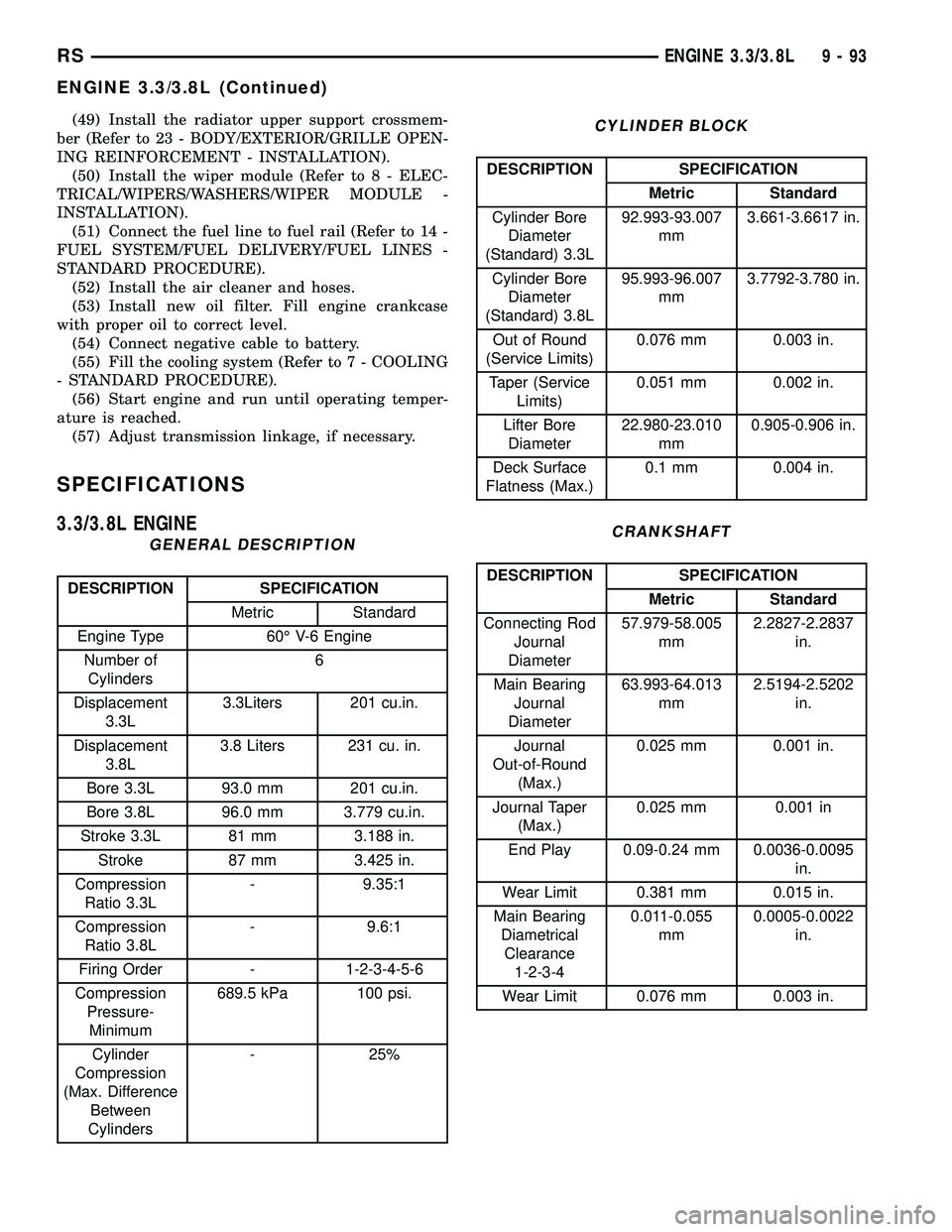
SPECIFICATIONS
3.3/3.8L ENGINE
GENERAL DESCRIPTION
DESCRIPTION SPECIFICATION
Metric Standard
Engine Type 60É V-6 Engine
Number of
Cylinders6
Displacement
3.3L3.3Liters 201 cu.in.
Displacement
3.8L3.8 Liters 231 cu. in.
Bore 3.3L 93.0 mm 201 cu.in.
Bore 3.8L 96.0 mm 3.779 cu.in.
Stroke 3.3L 81 mm 3.188 in.
Stroke 87 mm 3.425 in.
Compression
Ratio 3.3L- 9.35:1
Compression
Ratio 3.8L- 9.6:1
Firing Order - 1-2-3-4-5-6
Compression
Pressure-
Minimum689.5 kPa 100 psi.
Cylinder
Compression
(Max. Difference
Between
Cylinders- 25%
CYLINDER BLOCK
DESCRIPTION SPECIFICATION
Metric Standard
Cylinder Bore
Diameter
(Standard) 3.3L92.993-93.007
mm3.661-3.6617 in.
Cylinder Bore
Diameter
(Standard) 3.8L95.993-96.007
mm3.7792-3.780 in.
Out of Round
(Service Limits)0.076 mm 0.003 in.
Taper (Service
Limits)0.051 mm 0.002 in.
Lifter Bore
Diameter22.980-23.010
mm0.905-0.906 in.
Deck Surface
Flatness (Max.)0.1 mm 0.004 in.
CRANKSHAFT
DESCRIPTION SPECIFICATION
Metric Standard
Connecting Rod
Journal
Diameter57.979-58.005
mm2.2827-2.2837
in.
Main Bearing
Journal
Diameter63.993-64.013
mm2.5194-2.5202
in.
Journal
Out-of-Round
(Max.)0.025 mm 0.001 in.
Journal Taper
(Max.)0.025 mm 0.001 in
End Play 0.09-0.24 mm 0.0036-0.0095
in.
Wear Limit 0.381 mm 0.015 in.
Main Bearing
Diametrical
Clearance
1-2-3-40.011-0.055
mm0.0005-0.0022
in.
Wear Limit 0.076 mm 0.003 in.
RSENGINE 3.3/3.8L9-93
ENGINE 3.3/3.8L (Continued)
Page 1293 of 2339
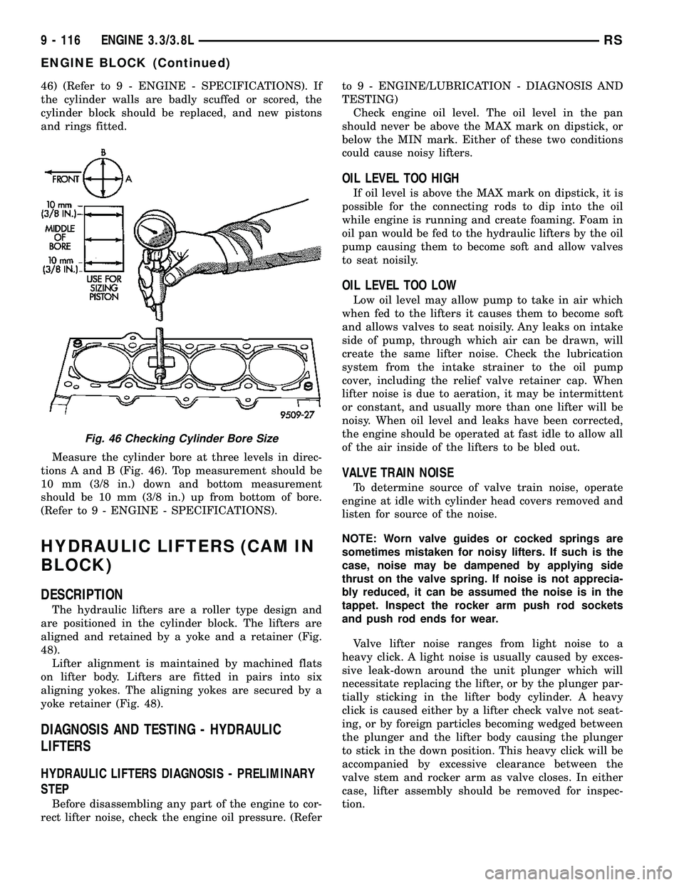
46) (Refer to 9 - ENGINE - SPECIFICATIONS). If
the cylinder walls are badly scuffed or scored, the
cylinder block should be replaced, and new pistons
and rings fitted.
Measure the cylinder bore at three levels in direc-
tions A and B (Fig. 46). Top measurement should be
10 mm (3/8 in.) down and bottom measurement
should be 10 mm (3/8 in.) up from bottom of bore.
(Refer to 9 - ENGINE - SPECIFICATIONS).
HYDRAULIC LIFTERS (CAM IN
BLOCK)
DESCRIPTION
The hydraulic lifters are a roller type design and
are positioned in the cylinder block. The lifters are
aligned and retained by a yoke and a retainer (Fig.
48).
Lifter alignment is maintained by machined flats
on lifter body. Lifters are fitted in pairs into six
aligning yokes. The aligning yokes are secured by a
yoke retainer (Fig. 48).
DIAGNOSIS AND TESTING - HYDRAULIC
LIFTERS
HYDRAULIC LIFTERS DIAGNOSIS - PRELIMINARY
STEP
Before disassembling any part of the engine to cor-
rect lifter noise, check the engine oil pressure. (Referto 9 - ENGINE/LUBRICATION - DIAGNOSIS AND
TESTING)
Check engine oil level. The oil level in the pan
should never be above the MAX mark on dipstick, or
below the MIN mark. Either of these two conditions
could cause noisy lifters.
OIL LEVEL TOO HIGH
If oil level is above the MAX mark on dipstick, it is
possible for the connecting rods to dip into the oil
while engine is running and create foaming. Foam in
oil pan would be fed to the hydraulic lifters by the oil
pump causing them to become soft and allow valves
to seat noisily.
OIL LEVEL TOO LOW
Low oil level may allow pump to take in air which
when fed to the lifters it causes them to become soft
and allows valves to seat noisily. Any leaks on intake
side of pump, through which air can be drawn, will
create the same lifter noise. Check the lubrication
system from the intake strainer to the oil pump
cover, including the relief valve retainer cap. When
lifter noise is due to aeration, it may be intermittent
or constant, and usually more than one lifter will be
noisy. When oil level and leaks have been corrected,
the engine should be operated at fast idle to allow all
of the air inside of the lifters to be bled out.
VALVE TRAIN NOISE
To determine source of valve train noise, operate
engine at idle with cylinder head covers removed and
listen for source of the noise.
NOTE: Worn valve guides or cocked springs are
sometimes mistaken for noisy lifters. If such is the
case, noise may be dampened by applying side
thrust on the valve spring. If noise is not apprecia-
bly reduced, it can be assumed the noise is in the
tappet. Inspect the rocker arm push rod sockets
and push rod ends for wear.
Valve lifter noise ranges from light noise to a
heavy click. A light noise is usually caused by exces-
sive leak-down around the unit plunger which will
necessitate replacing the lifter, or by the plunger par-
tially sticking in the lifter body cylinder. A heavy
click is caused either by a lifter check valve not seat-
ing, or by foreign particles becoming wedged between
the plunger and the lifter body causing the plunger
to stick in the down position. This heavy click will be
accompanied by excessive clearance between the
valve stem and rocker arm as valve closes. In either
case, lifter assembly should be removed for inspec-
tion.
Fig. 46 Checking Cylinder Bore Size
9 - 116 ENGINE 3.3/3.8LRS
ENGINE BLOCK (Continued)
Page 1298 of 2339
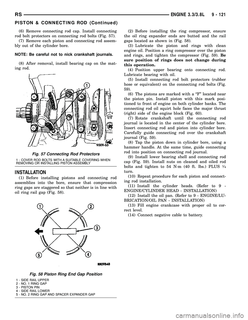
(6) Remove connecting rod cap. Install connecting
rod bolt protectors on connecting rod bolts (Fig. 57).
(7) Remove each piston and connecting rod assem-
bly out of the cylinder bore.
NOTE: Be careful not to nick crankshaft journals.
(8) After removal, install bearing cap on the mat-
ing rod.
INSTALLATION
(1) Before installing pistons and connecting rod
assemblies into the bore, ensure that compression
ring gaps are staggered so that neither is in line with
oil ring rail gap (Fig. 58).(2) Before installing the ring compressor, ensure
the oil ring expander ends are butted and the rail
gaps located as shown in (Fig. 58).
(3) Lubricate the piston and rings with clean
engine oil. Position a ring compressor over the piston
and rings, and tighten the compressor (Fig. 59).Be
sure position of rings does not change during
this operation.
(4) Position upper bearing onto connecting rod.
Lubricate bearing with oil.
(5) Install connecting rod bolt protectors (rubber
hose or equivalent) on the connecting rod bolts (Fig.
59).
(6) The pistons are marked with a ªFº located near
the piston pin. Install piston with this mark posi-
tioned to front of engine on both cylinder banks. The
connecting rod oil squirt hole faces the major thrust
(right) side of the engine block (Fig. 60).
(7) Rotate crankshaft until the connecting rod
journal is located in the center of the cylinder bore.
Insert connecting rod and piston into cylinder bore.
Carefully guide connecting rod over the crankshaft
journal (Fig. 59).
(8) Tap the piston down in cylinder bore, using a
hammer handle. At the same time, guide connecting
rod into position on connecting rod journal.
(9) Install lower bearing shell and connecting rod
cap (Fig. 59). Install nuts on cleaned and oiled rod
bolts and tighten to 54 N´m (40 ft. lbs.) PLUS
1¤4
turn.
(10) Repeat procedure for each piston and connect-
ing rod installation.
(11) Install the cylinder heads. (Refer to 9 -
ENGINE/CYLINDER HEAD - INSTALLATION)
(12) Install the oil pan. (Refer to 9 - ENGINE/LU-
BRICATION/OIL PAN - INSTALLATION)
(13) Fill engine crankcase with proper oil to cor-
rect level.
(14) Connect negative cable to battery.
Fig. 57 Connecting Rod Protectors
1 - COVER ROD BOLTS WITH A SUITABLE COVERING WHEN
REMOVING OR INSTALLING PISTON ASSEMBLY
Fig. 58 Piston Ring End Gap Position
1 - SIDE RAIL UPPER
2 - NO. 1 RING GAP
3 - PISTON PIN
4 - SIDE RAIL LOWER
5 - NO. 2 RING GAP AND SPACER EXPANDER GAP
RSENGINE 3.3/3.8L9 - 121
PISTON & CONNECTING ROD (Continued)
Page 1305 of 2339
(6) Tighten number 1, 3 and 4 main cap bolts to 41
N´m + 1/4 Turn (30 ft. lbs.+ 1/4 Turn).
(7) Rotate the crankshaft until the number 6 pis-
ton is at TDC.
(8) To ensure correct thrust bearing alignment the
following procedure must be done:
a. Move crankshaft all the way to the rear of its
travel.
b. Then, move crankshaft all the way to the front
of its travel.
c. Wedge an appropriate tool between the rear of
the cylinder block and rear crankshaft counter-
weight. This will hold the crankshaft in it's most for-
ward position.
d. Tighten the #2 Thrust Bearing cap bolts to 41
N´m + 1/4 Turn (30 ft. lbs.+ 1/4 Turn). Remove the
holding tool.
(9) Install oil pan. (Refer to 9 - ENGINE/LUBRI-
CATION/OIL PAN - INSTALLATION)
(10) Fill engine crankcase with proper oil to cor-
rect level.
CRANKSHAFT
DESCRIPTION
DESCRIPTION - 3.3L
The nodular iron crankshaft is supported by four
main bearings, with number two position the thrust
bearing (Fig. 76). Crankshaft end sealing is provided
by front and rear rubber seals.
DESCRIPTION - 3.8L
The nodular iron crankshaft is supported by four
main bearings, with number two position providing
thrust bearing location (Fig. 77). Each main bearing
cap has two vertical retaining bolts. The two center
main caps have horizontal bolts to add increasedrigidity to the lower engine block (Fig. 77). Crank-
shaft end sealing is provided by front and rear rub-
ber seals.
STANDARD PROCEDURE - MEASURING
CRANKSHAFT END PLAY
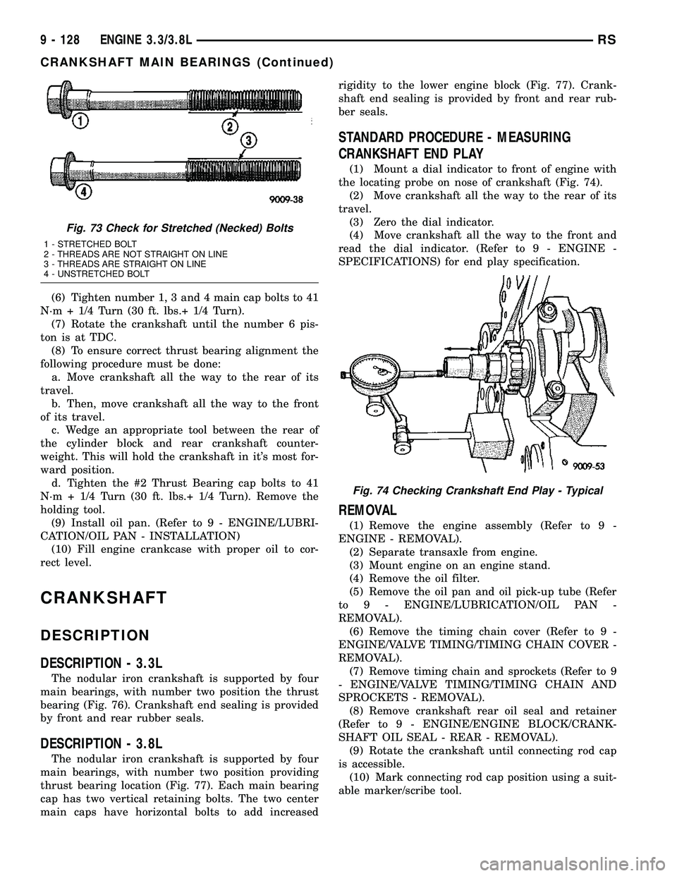
(1) Mount a dial indicator to front of engine with
the locating probe on nose of crankshaft (Fig. 74).
(2) Move crankshaft all the way to the rear of its
travel.
(3) Zero the dial indicator.
(4) Move crankshaft all the way to the front and
read the dial indicator. (Refer to 9 - ENGINE -
SPECIFICATIONS) for end play specification.
REMOVAL
(1) Remove the engine assembly (Refer to 9 -
ENGINE - REMOVAL).
(2) Separate transaxle from engine.
(3) Mount engine on an engine stand.
(4) Remove the oil filter.
(5) Remove the oil pan and oil pick-up tube (Refer
to 9 - ENGINE/LUBRICATION/OIL PAN -
REMOVAL).
(6) Remove the timing chain cover (Refer to 9 -
ENGINE/VALVE TIMING/TIMING CHAIN COVER -
REMOVAL).
(7) Remove timing chain and sprockets (Refer to 9
- ENGINE/VALVE TIMING/TIMING CHAIN AND
SPROCKETS - REMOVAL).
(8) Remove crankshaft rear oil seal and retainer
(Refer to 9 - ENGINE/ENGINE BLOCK/CRANK-
SHAFT OIL SEAL - REAR - REMOVAL).
(9) Rotate the crankshaft until connecting rod cap
is accessible.
(10) Mark connecting rod cap position using a suit-
able marker/scribe tool.
Fig. 73 Check for Stretched (Necked) Bolts
1 - STRETCHED BOLT
2 - THREADS ARE NOT STRAIGHT ON LINE
3 - THREADS ARE STRAIGHT ON LINE
4 - UNSTRETCHED BOLT
Fig. 74 Checking Crankshaft End Play - Typical
9 - 128 ENGINE 3.3/3.8LRS
CRANKSHAFT MAIN BEARINGS (Continued)