2005 CHRYSLER CARAVAN lock
[x] Cancel search: lockPage 1434 of 2339
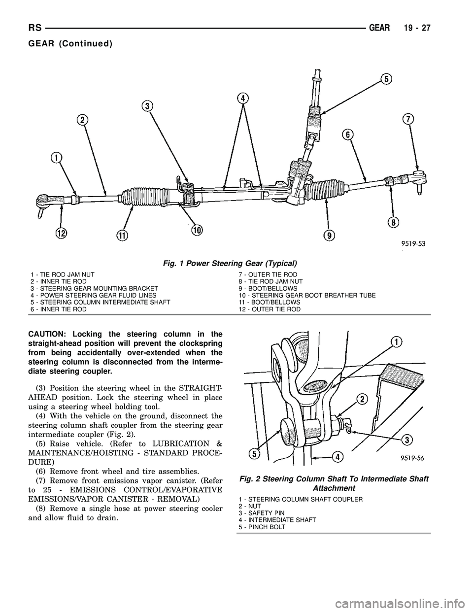
CAUTION: Locking the steering column in the
straight-ahead position will prevent the clockspring
from being accidentally over-extended when the
steering column is disconnected from the interme-
diate steering coupler.
(3) Position the steering wheel in the STRAIGHT-
AHEAD position. Lock the steering wheel in place
using a steering wheel holding tool.
(4) With the vehicle on the ground, disconnect the
steering column shaft coupler from the steering gear
intermediate coupler (Fig. 2).
(5) Raise vehicle. (Refer to LUBRICATION &
MAINTENANCE/HOISTING - STANDARD PROCE-
DURE)
(6) Remove front wheel and tire assemblies.
(7) Remove front emissions vapor canister. (Refer
to 25 - EMISSIONS CONTROL/EVAPORATIVE
EMISSIONS/VAPOR CANISTER - REMOVAL)
(8) Remove a single hose at power steering cooler
and allow fluid to drain.
Fig. 1 Power Steering Gear (Typical)
1 - TIE ROD JAM NUT
2 - INNER TIE ROD
3 - STEERING GEAR MOUNTING BRACKET
4 - POWER STEERING GEAR FLUID LINES
5 - STEERING COLUMN INTERMEDIATE SHAFT
6 - INNER TIE ROD7 - OUTER TIE ROD
8 - TIE ROD JAM NUT
9 - BOOT/BELLOWS
10 - STEERING GEAR BOOT BREATHER TUBE
11 - BOOT/BELLOWS
12 - OUTER TIE ROD
Fig. 2 Steering Column Shaft To Intermediate Shaft
Attachment
1 - STEERING COLUMN SHAFT COUPLER
2 - NUT
3 - SAFETY PIN
4 - INTERMEDIATE SHAFT
5 - PINCH BOLT
RSGEAR19-27
GEAR (Continued)
Page 1436 of 2339
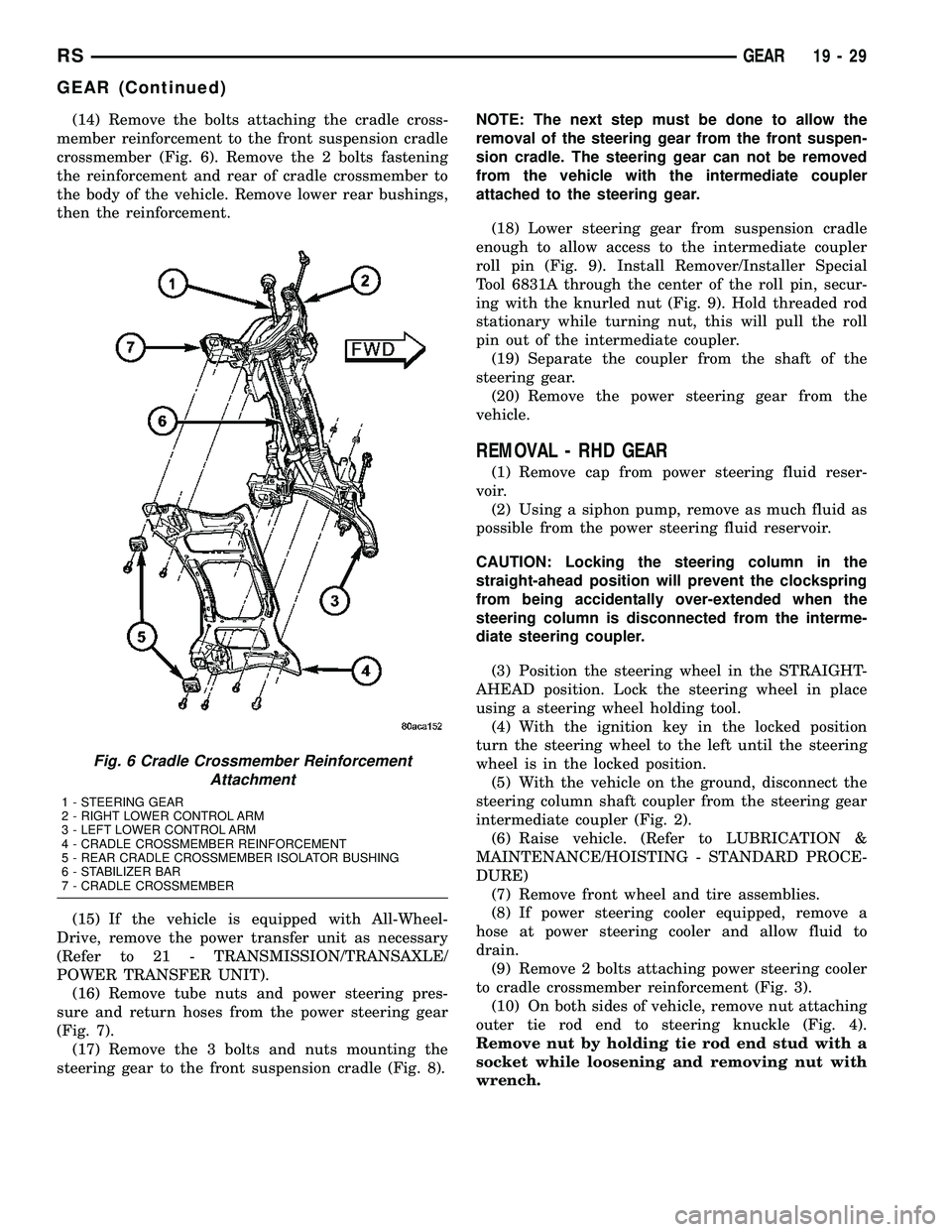
(14) Remove the bolts attaching the cradle cross-
member reinforcement to the front suspension cradle
crossmember (Fig. 6). Remove the 2 bolts fastening
the reinforcement and rear of cradle crossmember to
the body of the vehicle. Remove lower rear bushings,
then the reinforcement.
(15) If the vehicle is equipped with All-Wheel-
Drive, remove the power transfer unit as necessary
(Refer to 21 - TRANSMISSION/TRANSAXLE/
POWER TRANSFER UNIT).
(16) Remove tube nuts and power steering pres-
sure and return hoses from the power steering gear
(Fig. 7).
(17) Remove the 3 bolts and nuts mounting the
steering gear to the front suspension cradle (Fig. 8).NOTE: The next step must be done to allow the
removal of the steering gear from the front suspen-
sion cradle. The steering gear can not be removed
from the vehicle with the intermediate coupler
attached to the steering gear.
(18) Lower steering gear from suspension cradle
enough to allow access to the intermediate coupler
roll pin (Fig. 9). Install Remover/Installer Special
Tool 6831A through the center of the roll pin, secur-
ing with the knurled nut (Fig. 9). Hold threaded rod
stationary while turning nut, this will pull the roll
pin out of the intermediate coupler.
(19) Separate the coupler from the shaft of the
steering gear.
(20) Remove the power steering gear from the
vehicle.
REMOVAL - RHD GEAR
(1) Remove cap from power steering fluid reser-
voir.
(2) Using a siphon pump, remove as much fluid as
possible from the power steering fluid reservoir.
CAUTION: Locking the steering column in the
straight-ahead position will prevent the clockspring
from being accidentally over-extended when the
steering column is disconnected from the interme-
diate steering coupler.
(3) Position the steering wheel in the STRAIGHT-
AHEAD position. Lock the steering wheel in place
using a steering wheel holding tool.
(4) With the ignition key in the locked position
turn the steering wheel to the left until the steering
wheel is in the locked position.
(5) With the vehicle on the ground, disconnect the
steering column shaft coupler from the steering gear
intermediate coupler (Fig. 2).
(6) Raise vehicle. (Refer to LUBRICATION &
MAINTENANCE/HOISTING - STANDARD PROCE-
DURE)
(7) Remove front wheel and tire assemblies.
(8) If power steering cooler equipped, remove a
hose at power steering cooler and allow fluid to
drain.
(9) Remove 2 bolts attaching power steering cooler
to cradle crossmember reinforcement (Fig. 3).
(10) On both sides of vehicle, remove nut attaching
outer tie rod end to steering knuckle (Fig. 4).
Remove nut by holding tie rod end stud with a
socket while loosening and removing nut with
wrench.
Fig. 6 Cradle Crossmember Reinforcement
Attachment
1 - STEERING GEAR
2 - RIGHT LOWER CONTROL ARM
3 - LEFT LOWER CONTROL ARM
4 - CRADLE CROSSMEMBER REINFORCEMENT
5 - REAR CRADLE CROSSMEMBER ISOLATOR BUSHING
6 - STABILIZER BAR
7 - CRADLE CROSSMEMBER
RSGEAR19-29
GEAR (Continued)
Page 1445 of 2339
Read the fluid level through the side of the power
steering fluid reservoir. The fluid level should indi-
cateªFILL RANGEºwhen the fluid is at a temper-
ature of approximately 21ÉC to 27ÉC (70ÉF to 80ÉF).
(1) Wipe the filler cap and area clean, then remove
the cap.
(2) Fill the fluid reservoir to the proper level and
let the fluid settle for at least two (2) minutes.
(3) Start the engine and let run for a few seconds,
then turn the engine off.
(4) Add fluid if necessary. Repeat the above steps
until the fluid level remains constant after running
the engine.
(5) Raise the front wheels off the ground.
(6) Start the engine.
(7) Slowly turn the steering wheel right and left,
lightly contacting the wheel stops.
(8) Add fluid if necessary.
(9) Lower the vehicle, then turn the steering wheel
slowly from lock-to-lock.
(10) Stop the engine. Check the fluid level and
refill as required.
(11) If the fluid is extremely foamy, allow the vehi-
cle to stabilize a few minutes, then repeat the above
procedure.
REMOVAL
REMOVAL - PUMP (2.4L ENGINE)
(1) Remove the (-) negative battery cable from the
battery and isolate cable.
(2) Remove the cap from the power steering fluid
reservoir.
(3) Using a siphon pump, remove as much power
steering fluid as possible from the power steering
fluid reservoir.
(4) Raise the vehicle on jack stands or centered on
a frame contact type hoist. See Hoisting in Lubrica-
tion and Maintenance.
(5) Disconnect the oxygen sensor wiring harness
from the vehicle wiring harness at the rear engine
mount bracket.
NOTE: The exhaust system needs to be removed
from the engine to allow for an area to remove the
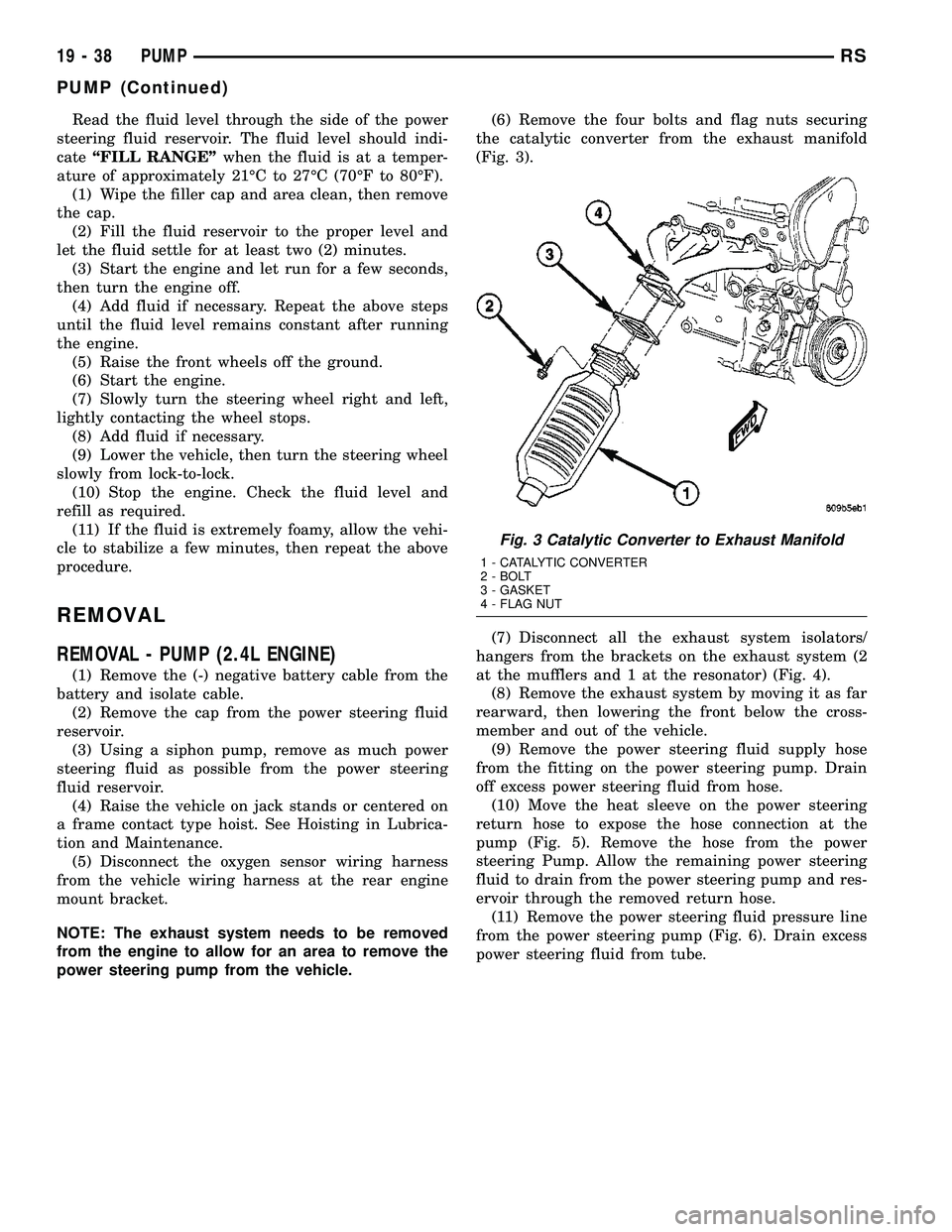
power steering pump from the vehicle.(6) Remove the four bolts and flag nuts securing
the catalytic converter from the exhaust manifold
(Fig. 3).
(7) Disconnect all the exhaust system isolators/
hangers from the brackets on the exhaust system (2
at the mufflers and 1 at the resonator) (Fig. 4).
(8) Remove the exhaust system by moving it as far
rearward, then lowering the front below the cross-
member and out of the vehicle.
(9) Remove the power steering fluid supply hose
from the fitting on the power steering pump. Drain
off excess power steering fluid from hose.
(10) Move the heat sleeve on the power steering
return hose to expose the hose connection at the
pump (Fig. 5). Remove the hose from the power
steering Pump. Allow the remaining power steering
fluid to drain from the power steering pump and res-
ervoir through the removed return hose.
(11) Remove the power steering fluid pressure line
from the power steering pump (Fig. 6). Drain excess
power steering fluid from tube.
Fig. 3 Catalytic Converter to Exhaust Manifold
1 - CATALYTIC CONVERTER
2 - BOLT
3 - GASKET
4 - FLAG NUT
19 - 38 PUMPRS
PUMP (Continued)
Page 1462 of 2339
TRANSMISSION/TRANSAXLE
TABLE OF CONTENTS
page page
40TE AUTOMATIC TRANSAXLE..............141TE AUTOMATIC TRANSAXLE............146
40TE AUTOMATIC TRANSAXLE
TABLE OF CONTENTS
page page
40TE AUTOMATIC TRANSAXLE
DESCRIPTION..........................2
OPERATION............................4
DIAGNOSIS AND TESTING
DIAGNOSIS AND TESTING - 4XTE
TRANSAXLE GENERAL DIAGNOSIS........5
DIAGNOSIS AND TESTING - ROAD TEST....5
DIAGNOSIS AND TESTING - HYDRAULIC
PRESSURE TESTS.....................6
DIAGNOSIS AND TESTING - CLUTCH AIR
PRESSURE TESTS.....................8
DIAGNOSIS AND TESTING - TORQUE
CONVERTER HOUSING FLUID LEAKAGE....9
REMOVAL.............................9
DISASSEMBLY.........................12
ASSEMBLY............................29
INSTALLATION.........................51
SCHEMATICS AND DIAGRAMS
4XTE TRANSAXLE HYDRAULIC
SCHEMATICS........................54
SPECIFICATIONS - 41TE TRANSAXLE.......66
SPECIAL TOOLS.......................68
ACCUMULATOR
DESCRIPTION.........................73
OPERATION...........................73
DRIVING CLUTCHES
DESCRIPTION.........................74
OPERATION...........................74
FINAL DRIVE
DESCRIPTION.........................74
OPERATION...........................75
DISASSEMBLY.........................75
ASSEMBLY............................78
ADJUSTMENTS
DIFFERENTIAL BEARING PRELOAD
MEASUREMENT AND ADJUSTMENT......79FLUID
STANDARD PROCEDURE
FLUID LEVEL AND CONDITION CHECK....82
STANDARD PROCEDURE - FLUID AND
FILTER SERVICE......................82
GEAR SHIFT CABLE
REMOVAL.............................84
HOLDING CLUTCHES
DESCRIPTION.........................86
OPERATION...........................86
INPUT CLUTCH ASSEMBLY
DISASSEMBLY.........................86
ASSEMBLY............................95
OIL PUMP
DESCRIPTION........................110
OPERATION..........................110
DISASSEMBLY........................110
ASSEMBLY...........................112
PLANETARY GEARTRAIN
DESCRIPTION........................112
OPERATION..........................112
SEAL - OIL PUMP
REMOVAL............................113
INSTALLATION........................113
SHIFT INTERLOCK SOLENOID
DESCRIPTION........................113
OPERATION..........................114
DIAGNOSIS AND TESTING - BRAKE/
TRANSMISSION SHIFT INTERLOCK
SOLENOID..........................115
REMOVAL............................115
INSTALLATION........................116
SOLENOID/PRESSURE SWITCH ASSY
DESCRIPTION........................117
OPERATION..........................118
REMOVAL............................118
INSTALLATION........................119
RSTRANSMISSION/TRANSAXLE21-1
Page 1469 of 2339
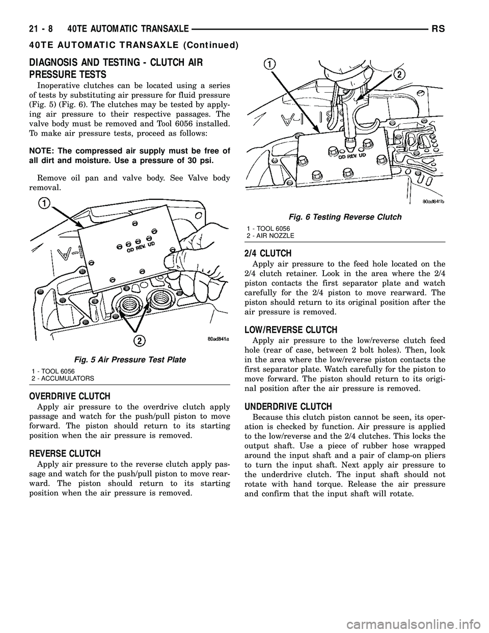
DIAGNOSIS AND TESTING - CLUTCH AIR
PRESSURE TESTS
Inoperative clutches can be located using a series
of tests by substituting air pressure for fluid pressure
(Fig. 5) (Fig. 6). The clutches may be tested by apply-
ing air pressure to their respective passages. The
valve body must be removed and Tool 6056 installed.
To make air pressure tests, proceed as follows:
NOTE: The compressed air supply must be free of
all dirt and moisture. Use a pressure of 30 psi.
Remove oil pan and valve body. See Valve body
removal.
OVERDRIVE CLUTCH
Apply air pressure to the overdrive clutch apply
passage and watch for the push/pull piston to move
forward. The piston should return to its starting
position when the air pressure is removed.
REVERSE CLUTCH
Apply air pressure to the reverse clutch apply pas-
sage and watch for the push/pull piston to move rear-
ward. The piston should return to its starting
position when the air pressure is removed.
2/4 CLUTCH
Apply air pressure to the feed hole located on the
2/4 clutch retainer. Look in the area where the 2/4
piston contacts the first separator plate and watch
carefully for the 2/4 piston to move rearward. The
piston should return to its original position after the
air pressure is removed.
LOW/REVERSE CLUTCH
Apply air pressure to the low/reverse clutch feed
hole (rear of case, between 2 bolt holes). Then, look
in the area where the low/reverse piston contacts the
first separator plate. Watch carefully for the piston to
move forward. The piston should return to its origi-
nal position after the air pressure is removed.
UNDERDRIVE CLUTCH
Because this clutch piston cannot be seen, its oper-
ation is checked by function. Air pressure is applied
to the low/reverse and the 2/4 clutches. This locks the
output shaft. Use a piece of rubber hose wrapped
around the input shaft and a pair of clamp-on pliers
to turn the input shaft. Next apply air pressure to
the underdrive clutch. The input shaft should not
rotate with hand torque. Release the air pressure
and confirm that the input shaft will rotate.
Fig. 5 Air Pressure Test Plate
1 - TOOL 6056
2 - ACCUMULATORS
Fig. 6 Testing Reverse Clutch
1 - TOOL 6056
2 - AIR NOZZLE
21 - 8 40TE AUTOMATIC TRANSAXLERS
40TE AUTOMATIC TRANSAXLE (Continued)
Page 1472 of 2339
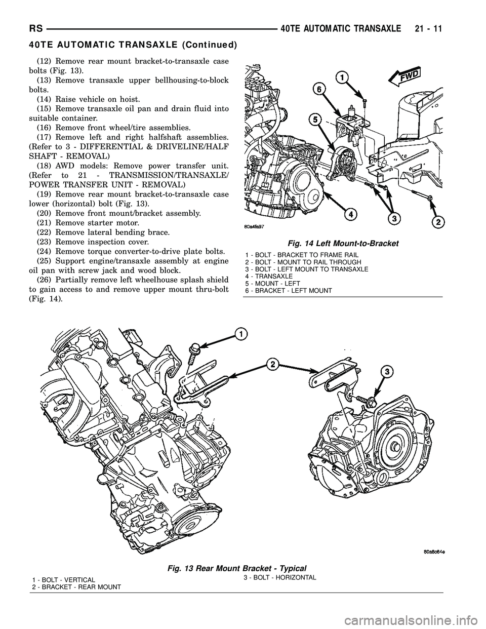
(12) Remove rear mount bracket-to-transaxle case
bolts (Fig. 13).
(13) Remove transaxle upper bellhousing-to-block
bolts.
(14) Raise vehicle on hoist.
(15) Remove transaxle oil pan and drain fluid into
suitable container.
(16) Remove front wheel/tire assemblies.
(17) Remove left and right halfshaft assemblies.
(Refer to 3 - DIFFERENTIAL & DRIVELINE/HALF
SHAFT - REMOVAL)
(18) AWD models: Remove power transfer unit.
(Refer to 21 - TRANSMISSION/TRANSAXLE/
POWER TRANSFER UNIT - REMOVAL)
(19) Remove rear mount bracket-to-transaxle case
lower (horizontal) bolt (Fig. 13).
(20) Remove front mount/bracket assembly.
(21) Remove starter motor.
(22) Remove lateral bending brace.
(23) Remove inspection cover.
(24) Remove torque converter-to-drive plate bolts.
(25) Support engine/transaxle assembly at engine
oil pan with screw jack and wood block.
(26) Partially remove left wheelhouse splash shield
to gain access to and remove upper mount thru-bolt
(Fig. 14).
Fig. 13 Rear Mount Bracket - Typical
1 - BOLT - VERTICAL
2 - BRACKET - REAR MOUNT3 - BOLT - HORIZONTAL
Fig. 14 Left Mount-to-Bracket
1 - BOLT - BRACKET TO FRAME RAIL
2 - BOLT - MOUNT TO RAIL THROUGH
3 - BOLT - LEFT MOUNT TO TRANSAXLE
4 - TRANSAXLE
5 - MOUNT - LEFT
6 - BRACKET - LEFT MOUNT
RS40TE AUTOMATIC TRANSAXLE21-11
40TE AUTOMATIC TRANSAXLE (Continued)
Page 1474 of 2339
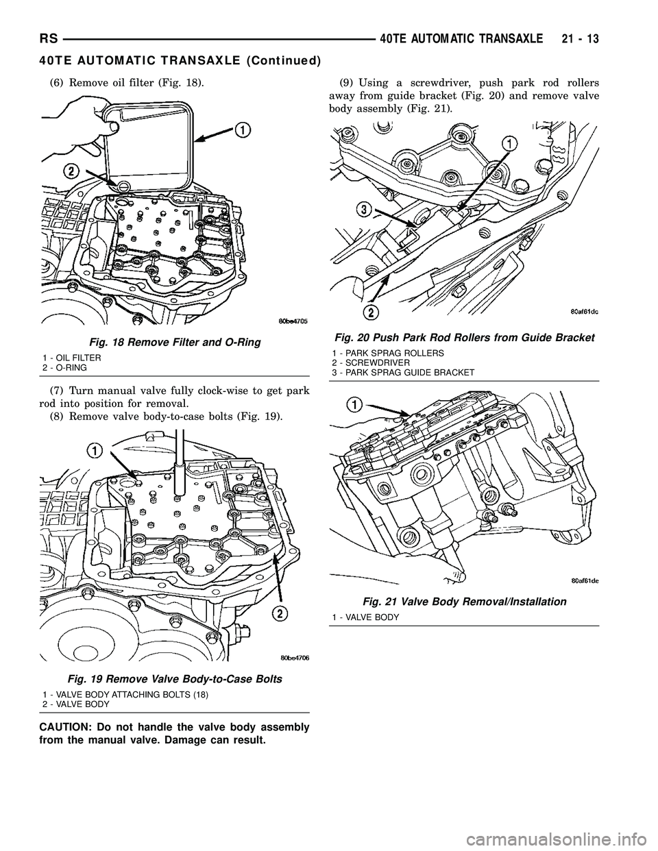
(6) Remove oil filter (Fig. 18).
(7) Turn manual valve fully clock-wise to get park
rod into position for removal.
(8) Remove valve body-to-case bolts (Fig. 19).
CAUTION: Do not handle the valve body assembly
from the manual valve. Damage can result.(9) Using a screwdriver, push park rod rollers
away from guide bracket (Fig. 20) and remove valve
body assembly (Fig. 21).
Fig. 18 Remove Filter and O-Ring
1 - OIL FILTER
2 - O-RING
Fig. 19 Remove Valve Body-to-Case Bolts
1 - VALVE BODY ATTACHING BOLTS (18)
2 - VALVE BODY
Fig. 20 Push Park Rod Rollers from Guide Bracket
1 - PARK SPRAG ROLLERS
2 - SCREWDRIVER
3 - PARK SPRAG GUIDE BRACKET
Fig. 21 Valve Body Removal/Installation
1 - VALVE BODY
RS40TE AUTOMATIC TRANSAXLE21-13
40TE AUTOMATIC TRANSAXLE (Continued)
Page 1479 of 2339
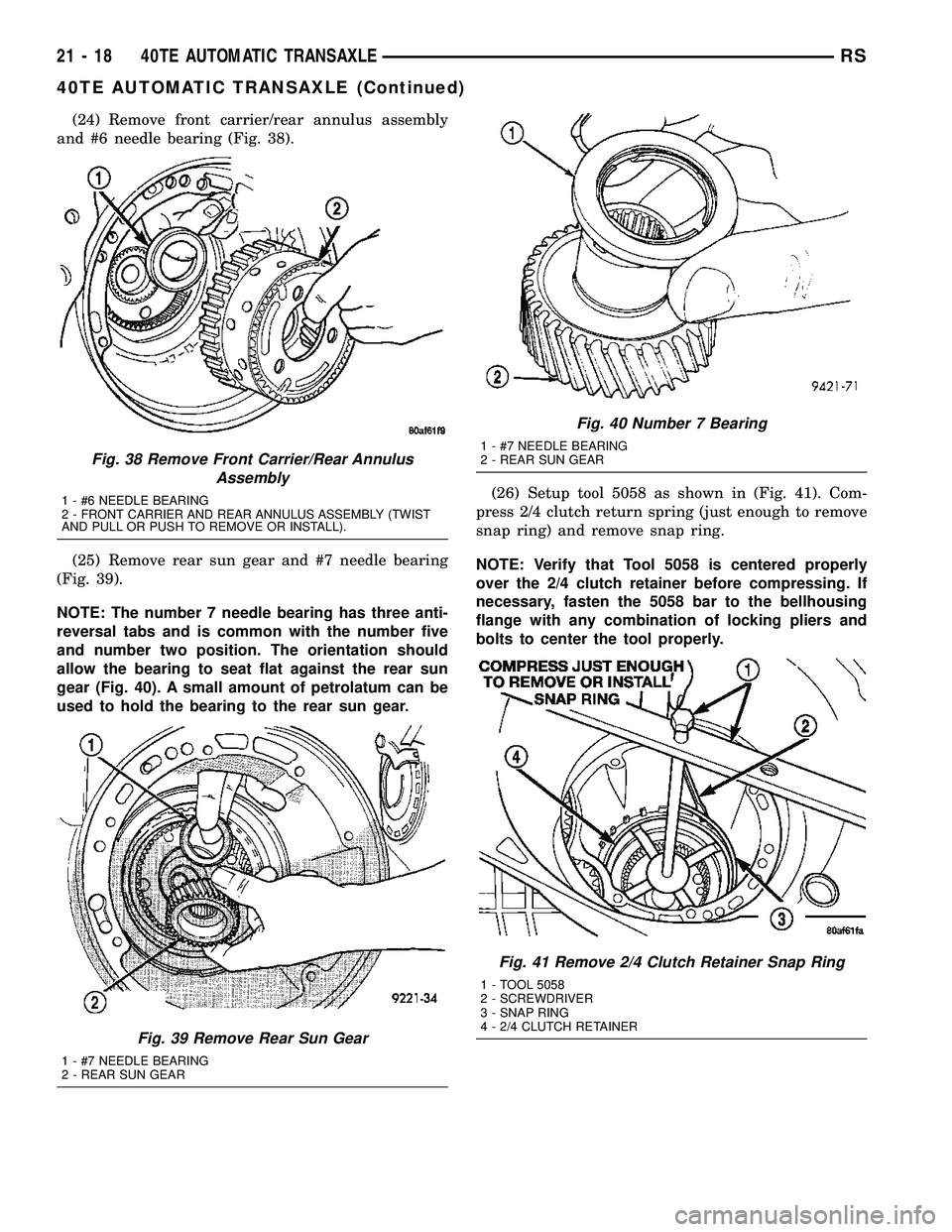
(24) Remove front carrier/rear annulus assembly
and #6 needle bearing (Fig. 38).
(25) Remove rear sun gear and #7 needle bearing
(Fig. 39).
NOTE: The number 7 needle bearing has three anti-
reversal tabs and is common with the number five
and number two position. The orientation should
allow the bearing to seat flat against the rear sun
gear (Fig. 40). A small amount of petrolatum can be
used to hold the bearing to the rear sun gear.(26) Setup tool 5058 as shown in (Fig. 41). Com-
press 2/4 clutch return spring (just enough to remove
snap ring) and remove snap ring.
NOTE: Verify that Tool 5058 is centered properly
over the 2/4 clutch retainer before compressing. If
necessary, fasten the 5058 bar to the bellhousing
flange with any combination of locking pliers and
bolts to center the tool properly.
Fig. 38 Remove Front Carrier/Rear Annulus
Assembly
1 - #6 NEEDLE BEARING
2 - FRONT CARRIER AND REAR ANNULUS ASSEMBLY (TWIST
AND PULL OR PUSH TO REMOVE OR INSTALL).
Fig. 39 Remove Rear Sun Gear
1 - #7 NEEDLE BEARING
2 - REAR SUN GEAR
Fig. 40 Number 7 Bearing
1 - #7 NEEDLE BEARING
2 - REAR SUN GEAR
Fig. 41 Remove 2/4 Clutch Retainer Snap Ring
1 - TOOL 5058
2 - SCREWDRIVER
3 - SNAP RING
4 - 2/4 CLUTCH RETAINER
21 - 18 40TE AUTOMATIC TRANSAXLERS
40TE AUTOMATIC TRANSAXLE (Continued)