Page 1482 of 2339
(35) Remove transfer gear cover-to-case bolts (Fig.
50).
(36) Remove transfer gear cover (Fig. 51).(37) Using Tool 6259, remove transfer shaft gear-
to-shaft nut and coned washer (Fig. 52) (Fig. 53).
Fig. 50 Remove Rear Cover Bolts
1 - REAR COVER BOLTS
2 - REAR COVER
3 - USE SEALANT ON BOLTS
Fig. 51 Remove Rear Cover
1 - REAR COVER
2 - 1/8 INCH BEAD OF MOPARTATF RTV (MS-GF41) AS SHOWN
Fig. 52 Remove Transfer Shaft Gear Nut
1 - TRANSFER SHAFT GEAR
2 - OUTPUT GEAR
3 - SPECIAL TOOL 6259
Fig. 53 Transfer Shaft Gear Nut and Coned Washer
1 - TRANSFER SHAFT
2 - LOCK WASHER
3 - NUT
RS40TE AUTOMATIC TRANSAXLE21-21
40TE AUTOMATIC TRANSAXLE (Continued)
Page 1485 of 2339
(46) Using tool P-334, press transfer shaft bearing
cone off of shaft (Fig. 62).
(47) Bend output gear retaining strap ears flat to
allow bolt removal.
(48) Remove output shaft stirrup strap bolts (Fig.
63).
(49) Remove stirrup and strap (Fig. 64).
(50) Using Tool 6259 (Fig. 65), remove output shaft
gear-to-shaft bolt and washer (Fig. 66).
Fig. 65 Remove Output Gear Bolt
1 - OUTPUT GEAR
2 - TOOL 6259
Fig. 62 Remove Transfer Shaft Bearing Cone
1 - ARBOR PRESS RAM
2 - TRANSFER SHAFT
3 - TOOL P-334
4 - BEARING CONE
Fig. 63 Remove Strap Bolts
1 - RETAINING STRAP
2 - STIRRUP
3 - RETAINING STRAP BOLTS
Fig. 64 Remove Stirrup Strap
1 - OUTPUT GEARBOLT
2 - RETAINING STRAP
3 - STIRRUP
Fig. 66 Output Gear Bolt and Washer
1 - OUTPUT GEAR
2 - BOLT
3 - CONED LOCK WASHER
21 - 24 40TE AUTOMATIC TRANSAXLERS
40TE AUTOMATIC TRANSAXLE (Continued)
Page 1496 of 2339

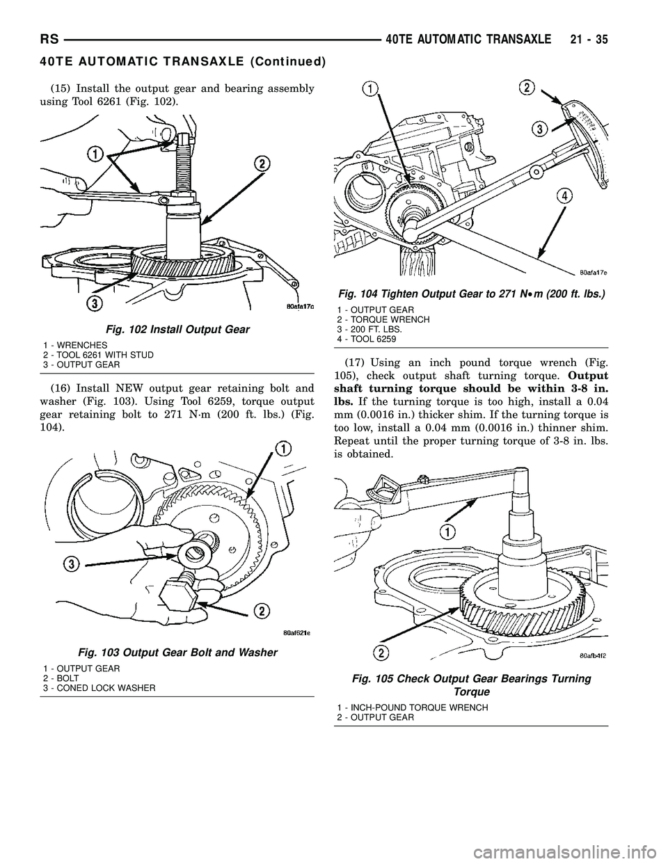
(15) Install the output gear and bearing assembly
using Tool 6261 (Fig. 102).
(16) Install NEW output gear retaining bolt and
washer (Fig. 103). Using Tool 6259, torque output
gear retaining bolt to 271 N´m (200 ft. lbs.) (Fig.
104).(17) Using an inch pound torque wrench (Fig.
105), check output shaft turning torque.Output
shaft turning torque should be within 3-8 in.
lbs.If the turning torque is too high, install a 0.04
mm (0.0016 in.) thicker shim. If the turning torque is
too low, install a 0.04 mm (0.0016 in.) thinner shim.
Repeat until the proper turning torque of 3-8 in. lbs.
is obtained.
Fig. 102 Install Output Gear
1 - WRENCHES
2 - TOOL 6261 WITH STUD
3 - OUTPUT GEAR
Fig. 103 Output Gear Bolt and Washer
1 - OUTPUT GEAR
2 - BOLT
3 - CONED LOCK WASHER
Fig. 104 Tighten Output Gear to 271 N²m (200 ft. lbs.)
1 - OUTPUT GEAR
2 - TORQUE WRENCH
3 - 200 FT. LBS.
4 - TOOL 6259
Fig. 105 Check Output Gear Bearings Turning
Torque
1 - INCH-POUND TORQUE WRENCH
2 - OUTPUT GEAR
RS40TE AUTOMATIC TRANSAXLE21-35
40TE AUTOMATIC TRANSAXLE (Continued)
Page 1497 of 2339
(18) Install output gear stirrup with serrated side
out (Fig. 106).
(19) Install retaining strap (Fig. 107).
(20) Install strap bolts but do not tighten at this
time (Fig. 107).(21) Rotate stirrup clockwise against flats of
retaining bolt (Fig. 108).
(22) Torque stirrup strap bolts to 23 N´m (200 in.
lbs.) (Fig. 109).
Fig. 106 Install Stirrup
1 - STIRRUP
2 - OUTPUT GEAR RETAINING BOLT
Fig. 107 Install Strap Bolts
1 - RETAINING STRAP
2 - STIRRUP
3 - RETAINING STRAP BOLTS
Fig. 108 Turn Stirrup Clockwise Against Flats Of
Output Gear Retaining Bolt
1 - RETAINING STRAP
2 - STIRRUP
Fig. 109 Tighten Stirrup Strap Bolts to 23 N´m (200
in. lbs.)
1 - RETAINING STRAP
2 - STIRRUP
21 - 36 40TE AUTOMATIC TRANSAXLERS
40TE AUTOMATIC TRANSAXLE (Continued)
Page 1510 of 2339
(60) Install low/reverse accumulator plug (Fig.
150).
(61) Install low/reverse accumulator snap ring
(Fig. 151).NOTE: Depending on engine application, some
accumulators will have two springs, and others will
have one spring. The springs are color-coded for
application and year.
(62) Install underdrive and overdrive accumulators
and springs (Fig. 152).
(63) Install valve body to transaxle (Fig. 153).
Rotate manual valve shaft fully clockwise to ease
installation. Make sure park rod rollers are posi-
tioned within park guide bracket.
Fig. 150 Install Low/Reverse Accumulator Plug
1 - ADJUSTABLE PLIERS
2 - PLUG
Fig. 151 Install Low/Reverse Accumulator Snap
Ring
1 - SNAP RING
2 - PLUG
Fig. 152 Underdrive and Overdrive Accumulators
1 - OVERDRIVE PISTON AND SPRING
2 - UNDERDRIVE PISTON AND SPRING
Fig. 153 Valve Body Removal/Installation
1 - VALVE BODY
RS40TE AUTOMATIC TRANSAXLE21-49
40TE AUTOMATIC TRANSAXLE (Continued)
Page 1512 of 2339

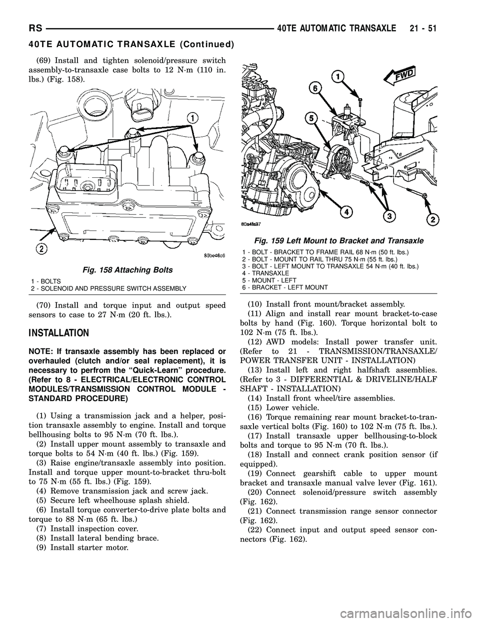
(69) Install and tighten solenoid/pressure switch
assembly-to-transaxle case bolts to 12 N´m (110 in.
lbs.) (Fig. 158).
(70) Install and torque input and output speed
sensors to case to 27 N´m (20 ft. lbs.).
INSTALLATION
NOTE: If transaxle assembly has been replaced or
overhauled (clutch and/or seal replacement), it is
necessary to perfrom the ªQuick-Learnº procedure.
(Refer to 8 - ELECTRICAL/ELECTRONIC CONTROL
MODULES/TRANSMISSION CONTROL MODULE -
STANDARD PROCEDURE)
(1) Using a transmission jack and a helper, posi-
tion transaxle assembly to engine. Install and torque
bellhousing bolts to 95 N´m (70 ft. lbs.).
(2) Install upper mount assembly to transaxle and
torque bolts to 54 N´m (40 ft. lbs.) (Fig. 159).
(3) Raise engine/transaxle assembly into position.
Install and torque upper mount-to-bracket thru-bolt
to 75 N´m (55 ft. lbs.) (Fig. 159).
(4) Remove transmission jack and screw jack.
(5) Secure left wheelhouse splash shield.
(6) Install torque converter-to-drive plate bolts and
torque to 88 N´m (65 ft. lbs.)
(7) Install inspection cover.
(8) Install lateral bending brace.
(9) Install starter motor.(10) Install front mount/bracket assembly.
(11) Align and install rear mount bracket-to-case
bolts by hand (Fig. 160). Torque horizontal bolt to
102 N´m (75 ft. lbs.).
(12) AWD models: Install power transfer unit.
(Refer to 21 - TRANSMISSION/TRANSAXLE/
POWER TRANSFER UNIT - INSTALLATION)
(13) Install left and right halfshaft assemblies.
(Refer to 3 - DIFFERENTIAL & DRIVELINE/HALF
SHAFT - INSTALLATION)
(14) Install front wheel/tire assemblies.
(15) Lower vehicle.
(16) Torque remaining rear mount bracket-to-tran-
saxle vertical bolts (Fig. 160) to 102 N´m (75 ft. lbs.).
(17) Install transaxle upper bellhousing-to-block
bolts and torque to 95 N´m (70 ft. lbs.).
(18) Install and connect crank position sensor (if
equipped).
(19) Connect gearshift cable to upper mount
bracket and transaxle manual valve lever (Fig. 161).
(20) Connect solenoid/pressure switch assembly
(Fig. 162).
(21) Connect transmission range sensor connector
(Fig. 162).
(22) Connect input and output speed sensor con-
nectors (Fig. 162).
Fig. 158 Attaching Bolts
1 - BOLTS
2 - SOLENOID AND PRESSURE SWITCH ASSEMBLY
Fig. 159 Left Mount to Bracket and Transaxle
1 - BOLT - BRACKET TO FRAME RAIL 68 N´m (50 ft. lbs.)
2 - BOLT - MOUNT TO RAIL THRU 75 N´m (55 ft. lbs.)
3 - BOLT - LEFT MOUNT TO TRANSAXLE 54 N´m (40 ft. lbs.)
4 - TRANSAXLE
5 - MOUNT - LEFT
6 - BRACKET - LEFT MOUNT
RS40TE AUTOMATIC TRANSAXLE21-51
40TE AUTOMATIC TRANSAXLE (Continued)
Page 1518 of 2339
Reverse Block (Shift to Reverse W/Speed Over 8 mph)
RS40TE AUTOMATIC TRANSAXLE21-57
40TE AUTOMATIC TRANSAXLE (Continued)
Page 1573 of 2339

(8) Position an appropriate piece of Plastigage
across both pump gears.
(9) Align the Plastigage to a flat area on the reac-
tion shaft support housing.
(10) Install the reaction shaft to the pump housing
(Fig. 256). Tighten the bolts to 27 N´m (20 ft. lbs.).
(11) Remove bolts and carefully separate the hous-
ings. Measure the Plastigage following the instruc-
tions supplied.
(12) Clearance between both gear end faces and
the reaction shaft support should be 0.020-0.046 mm
(0.0008-0.0018 in.).
ASSEMBLY
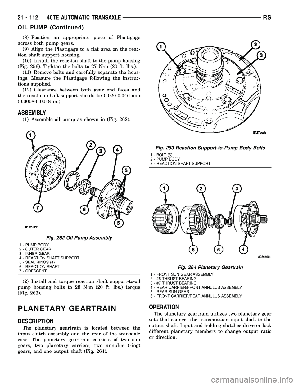
(1) Assemble oil pump as shown in (Fig. 262).
(2) Install and torque reaction shaft support-to-oil
pump housing bolts to 28 N´m (20 ft. lbs.) torque
(Fig. 263).
PLANETARY GEARTRAIN
DESCRIPTION
The planetary geartrain is located between the
input clutch assembly and the rear of the transaxle
case. The planetary geartrain consists of two sun
gears, two planetary carriers, two annulus (ring)
gears, and one output shaft (Fig. 264).
OPERATION
The planetary geartrain utilizes two planetary gear
sets that connect the transmission input shaft to the
output shaft. Input and holding clutches drive or lock
different planetary members to change output ratio
or direction.
Fig. 262 Oil Pump Assembly
1 - PUMP BODY
2 - OUTER GEAR
3 - INNER GEAR
4 - REACTION SHAFT SUPPORT
5 - SEAL RINGS (4)
6 - REACTION SHAFT
7 - CRESCENT
Fig. 263 Reaction Support-to-Pump Body Bolts
1 - BOLT (6)
2 - PUMP BODY
3 - REACTION SHAFT SUPPORT
Fig. 264 Planetary Geartrain
1 - FRONT SUN GEAR ASSEMBLY
2 - #6 THRUST BEARING
3 - #7 THRUST BEARING
4 - REAR CARRIER/FRONT ANNULUS ASSEMBLY
5 - REAR SUN GEAR
6 - FRONT CARRIER/REAR ANNULUS ASSEMBLY
21 - 112 40TE AUTOMATIC TRANSAXLERS
OIL PUMP (Continued)