2005 CHRYSLER CARAVAN open hood
[x] Cancel search: open hoodPage 654 of 2339

8W-15 GROUND DISTRIBUTION
Component Page
A/C Compressor Clutch...................8W-15-2, 9
A/C-Heater Control....................8W-15-10, 12
Adjustable Pedals Switch...................8W-15-11
Amplifier............................8W-15-27
Auto Temp Control......................8W-15-10
Back-Up Lamp Switch...................8W-15-2, 4
Battery...........................8W-15-2, 3, 4
Body Control Module.....................8W-15-24
Brake Fluid Level Switch..................8W-15-18
Brake Lamp Switch......................8W-15-18
Cabin Heater Assist......................8W-15-9
CD Changer...........................8W-15-13
Center High Mounted Stop Lamp.............8W-15-30
Clutch Pedal Interlock Switch................8W-15-18
Clutch Pedal Upstop Switch.................8W-15-19
Controller Antilock Brake.................8W-15-2, 4
Crank Case Ventilation Heater................8W-15-9
Crankshaft Position Sensor..................8W-15-4
Data Link Connector..................8W-15-3, 4, 18
Dosing Pump...........................8W-15-9
Driver Door Courtesy Lamp...............8W-15-15, 21
Driver Door Lock Switch.................8W-15-15, 21
Driver Heated Seat Cushion.................8W-15-17
Driver Heated Seat Module.................8W-15-17
Driver Power Seat Switch..................8W-15-17
Driver Power Window Switch..............8W-15-15, 21
DVD/CD Changer.......................8W-15-11
EGR Solenoid..........................8W-15-3
Engine Control Module.....................8W-15-4
Floor Console Lamp......................8W-15-28
Floor Console Power Outlet.................8W-15-28
Front Blower Module.....................8W-15-12
Front Cigar Lighter......................8W-15-10
Front Control Module................8W-15-2, 8, 9, 19
Front Reading Lamps/Switch................8W-15-22
Fuel Heater...........................8W-15-28
Fuel Heater Relay........................8W-15-4
Fuel Pump Module......................8W-15-28
G100..............................8W-15-2, 4
G101..............................8W-15-2, 4
G102.............................8W-15-5, 6, 7
G103................................8W-15-9
G200..........................8W-15-10, 11, 12
G201...............................8W-15-13
G202...............................8W-15-13
G300....................8W-15-12, 14, 16, 17, 18, 19
G301......................8W-15-20, 21, 22, 24, 25
G302..........................8W-15-26, 27, 28
G303..........................8W-15-28, 29, 30
Generator.............................8W-15-2
Hands Free Module......................8W-15-11
Headlamp Switch.......................8W-15-10
Headlamp Washer Pump Motor...............8W-15-7
High Note Horn.........................8W-15-6
Hood Ajar Switch.......................8W-15-19
Horn Switch..........................8W-15-12
Instrument Cluster......................8W-15-10
Instrument Panel Switch Bank...............8W-15-10
Integrated Power Module...........8W-15-2, 3, 4, 8, 9, 19
Left B-Pillar Switch......................8W-15-18
Left Cinch/Release Motor..................8W-15-14
Left Cylinder Lock Switch................8W-15-15, 16
Left Fog Lamp..........................8W-15-6
Left Front Door Ajar Switch.................8W-15-16
Left Front Door Lock Motor/Ajar Switch.......8W-15-15, 16
Left Front Park/Turn Signal Lamp.............8W-15-6
Left Full Open Switch....................8W-15-14
Left Headlamp.........................8W-15-19
Left Headlamp Leveling Motor................8W-15-7
Left High Beam Lamp...................8W-15-8, 19
Left Liftgate Flood Lamp...................8W-15-29
Left Low Beam Lamp...................8W-15-8, 19
Left Mid Reading Lamp...................8W-15-23
Left Park Lamp.......................8W-15-8, 19
Left Power Mirror.......................8W-15-12
Left Rear Lamp Assembly..................8W-15-28
Left Rear Reading Lamp...................8W-15-23
Left Sliding Door Control Module.............8W-15-14
Left Sliding Door Latch Sensing Switch..........8W-15-14
Left Sliding Door Lock Motor................8W-15-14
Left Sliding Door Lock Motor/Ajar Switch........8W-15-14
Left Sliding Door Motor...................8W-15-14Component Page
Left Turn Signal Lamp....................8W-15-19
Left Visor/Vanity Lamp....................8W-15-23
License Lamp.......................8W-15-26, 29
Lift Pump Motor........................8W-15-28
Liftgate Ajar Switch......................8W-15-30
Liftgate Cinch/Release Motor..............8W-15-26, 30
Liftgate Right Pinch Sensor.................8W-15-26
Memory Seat/Mirror/Adjustable Pedals Module.....8W-15-17
Natural Vacuum Leak Detection Assembly.......8W-15-2, 3
Occupant Classification Module...............8W-15-24
Occupant Restraint Controller...............8W-15-13
Overhead Console.......................8W-15-22
Oxygen Sensor 1/1 Upstream.................8W-15-3
Oxygen Sensor 1/2 Downstream...............8W-15-3
Park Assist Display......................8W-15-28
Park Assist Module......................8W-15-28
Passenger Door Courtesy Lamp............8W-15-16, 21
Passenger Door Lock Switch..............8W-15-16, 21
Passenger Heated Seat Back................8W-15-25
Passenger Heated Seat Cushion..............8W-15-25
Passenger Heated Seat Module...............8W-15-25
Passenger Power Seat Switch................8W-15-25
Power Folding Mirror Switch................8W-15-12
Power Liftgate Module..................8W-15-26, 28
Power Liftgate Motor.....................8W-15-26
Power Mirror Switch.....................8W-15-12
Power Outlet..........................8W-15-10
Power Window Switch....................8W-15-15
Powertrain Control Module..................8W-15-3
Radiator Fan No. 1.......................8W-15-5
Radiator Fan No. 2.......................8W-15-5
Radiator Fan Relay.......................8W-15-5
Radiator Fan Relay No. 3...................8W-15-5
Radio...............................8W-15-13
Rear Auto Temp Control Switch..............8W-15-18
Rear Blower Front Control Switch.............8W-15-12
Rear Blower Motor Power Module.............8W-15-28
Rear Blower Rear Control Switch.............8W-15-18
Rear Dome Lamp.....................8W-15-22, 23
Rear Power Outlet.......................8W-15-28
Rear View Mirror.....................8W-15-11, 22
Rear Window Defogger Grid.................8W-15-30
Rear Wiper Motor.......................8W-15-29
Right B-Pillar Switch.....................8W-15-24
Right Cinch/Release Motor..................8W-15-20
Right Cylinder Lock Switch.................8W-15-21
Right Fog Lamp.........................8W-15-6
Right Front Door Ajar Switch................8W-15-21
Right Front Door Lock Motor/Ajar Switch........8W-15-21
Right Front Park/Turn Signal Lamp............8W-15-6
Right Full Open Switch...................8W-15-20
Right Headlamp........................8W-15-19
Right Headlamp Leveling Motor...............8W-15-7
Right High Beam Lamp..................8W-15-8, 19
Right Liftgate Flood Lamp..................8W-15-29
Right Low Beam Lamp..................8W-15-8, 19
Right Mid Reading Lamp..................8W-15-23
Right Park Lamp......................8W-15-8, 19
Right Power Mirror....................8W-15-11, 12
Right Rear Lamp Assembly...............8W-15-27, 28
Right Rear Reading Lamp..................8W-15-23
Right Sliding Door Control Module............8W-15-20
Right Sliding Door Latch Sensing Switch.........8W-15-20
Right Sliding Door Lock Motor...............8W-15-20
Right Sliding Door Lock Motor/Ajar Switch.......8W-15-20
Right Sliding Door Motor..................8W-15-20
Right Turn Signal Lamp...................8W-15-19
Right Visor/Vanity Lamp...................8W-15-23
Sentry Key Remote Entry Module.............8W-15-11
Siren...............................8W-15-11
Speed Control Servo......................8W-15-2
Sunroof Module........................8W-15-27
Sunroof Switch.........................8W-15-23
Thatcham Alarm Module...................8W-15-11
Traction Control Switch...................8W-15-11
Trailer Tow Connector....................8W-15-27
Transmission Control Module.................8W-15-4
Transmission Control Relay................8W-15-3, 4
Washer Fluid Level Switch..................8W-15-5
Wiper Module..........................8W-15-18
RS8W-15 GROUND DISTRIBUTION8W-15-1
Page 972 of 2339

Component Page
Evaporator Temperature Sensor........ 8W-80-70
Floor Console Lamp................. 8W-80-70
Floor Console Power Outlet (Export).... 8W-80-70
Front Blower Module C1 (ATC)........ 8W-80-71
Front Blower Module C2 (ATC)........ 8W-80-71
Front Cigar Lighter................. 8W-80-71
Front Control Module................ 8W-80-72
Front Intrusion Sensor (United
Kingdom)....................... 8W-80-73
Front Reading Lamps/Switch.......... 8W-80-73
Fuel Heater (Diesel)................. 8W-80-73
Fuel Injector No. 1 (2.4L/3.3L/3.8L)..... 8W-80-73
Fuel Injector No. 1 (Diesel)............ 8W-80-73
Fuel Injector No. 2 (2.4L/3.3L/3.8L)..... 8W-80-74
Fuel Injector No. 2 (Diesel)............ 8W-80-74
Fuel Injector No. 3 (2.4L/3.3L/3.8L)..... 8W-80-74
Fuel Injector No. 3 (Diesel)............ 8W-80-74
Fuel Injector No. 4 (2.4L/3.3L/3.8L)..... 8W-80-75
Fuel Injector No. 4 (Diesel)............ 8W-80-75
Fuel Injector No. 5 (3.3L/3.8L)......... 8W-80-75
Fuel Injector No. 6 (3.3L/3.8L)......... 8W-80-75
Fuel Pressure Sensor (Diesel).......... 8W-80-76
Fuel Pressure Solenoid (Diesel)........ 8W-80-76
Fuel Pump Module.................. 8W-80-76
Generator......................... 8W-80-76
Glow Plug Relay (Diesel)............. 8W-80-77
Hands Free Module C1............... 8W-80-77
Hands Free Module C2............... 8W-80-77
Hands Free Module C3............... 8W-80-78
Headlamp Switch................... 8W-80-78
Headlamp Washer Pump Motor (Export) . 8W-80-78
High Note Horn.................... 8W-80-79
Hood Ajar Switch (Export)............ 8W-80-79
Idle Air Control Motor (Gas)........... 8W-80-79
Ignition Coil (2.4L).................. 8W-80-79
Ignition Coil (3.3L/3.8L).............. 8W-80-80
Ignition Switch..................... 8W-80-80
Inlet Air Temperature Sensor.......... 8W-80-80
Input Speed Sensor................. 8W-80-80
Instrument Cluster.................. 8W-80-81
Instrument Panel Switch Bank
(Except Heated Seats)............. 8W-80-81
Instrument Panel Switch Bank
(Heated Seats)................... 8W-80-81
Integrated Power Module C1.......... 8W-80-82
Integrated Power Module C2.......... 8W-80-82
Integrated Power Module C3.......... 8W-80-83
Integrated Power Module C4.......... 8W-80-83
Integrated Power Module C5.......... 8W-80-84
Integrated Power Module C6.......... 8W-80-84
Integrated Power Module C7.......... 8W-80-84
Integrated Power Module C8.......... 8W-80-85
Integrated Power Module C9.......... 8W-80-85
Knock Sensor (Except Export)......... 8W-80-85Component Page
Left B-Pillar Switch (Power Sliding
Door).......................... 8W-80-86
Left Cinch/Release Motor (Power Sliding
Door).......................... 8W-80-86
Left Curtain Airbag Squib............ 8W-80-86
Left Cylinder Lock Switch (Export)..... 8W-80-86
Left Door Speaker.................. 8W-80-87
Left Fog Lamp..................... 8W-80-87
Left Front Door Ajar Switch (Base)..... 8W-80-87
Left Front Door Lock Motor/Ajar Switch
(Except Base).................... 8W-80-87
Left Front Impact Sensor (Export)...... 8W-80-87
Left Front Impact Sensor (Except
Export)......................... 8W-80-88
Left Front Park/Turn Signal Lamp...... 8W-80-88
Left Front Wheel Speed Sensor........ 8W-80-88
Left Full Open Switch (Power Sliding
Door).......................... 8W-80-88
Left Headlamp (Caravan/Voyager Except
Export)......................... 8W-80-89
Left Headlamp (Town And Country)..... 8W-80-89
Left Headlamp Leveling Motor (Export) . . 8W-80-89
Left High Beam Lamp (Export)........ 8W-80-89
Left Instrument Panel Speaker........ 8W-80-90
Left Liftgate Flood Lamp (Export)...... 8W-80-90
Left Low Beam Lamp (Export)......... 8W-80-90
Left Mid Reading Lamp (Premium/
Luxury)........................ 8W-80-90
Left Park Lamp (Export)............. 8W-80-91
Left Power Mirror................... 8W-80-91
Left Rear Lamp Assembly............ 8W-80-91
Left Rear Pillar Speaker (Highline
Audio).......................... 8W-80-92
Left Rear Reading Lamp (Luxury)...... 8W-80-92
Left Rear Speaker.................. 8W-80-92
Left Rear Vent Motor................ 8W-80-92
Left Rear Wheel Speed Sensor......... 8W-80-93
Left Remote Radio Switch............ 8W-80-93
Left Repeater Lamp (Export).......... 8W-80-93
Left Side Impact Sensor 1 (Export)..... 8W-80-93
Left Side Impact Sensor 1 (Except
Export)......................... 8W-80-94
Left Side Impact Sensor 2............ 8W-80-94
Left Side Impact Sensor 3............ 8W-80-94
Left Sliding Door Control Module C1
(Power Sliding Door).............. 8W-80-94
Left Sliding Door Control Module C2
(Power Sliding Door).............. 8W-80-95
Left Sliding Door Latch Sensing Switch
(Power Sliding Door).............. 8W-80-95
Left Sliding Door Lock Motor (Power Sliding
Door).......................... 8W-80-95
Left Sliding Door Lock Motor/Ajar Switch
(Manual Sliding Door)............. 8W-80-96
RS8W-80 CONNECTOR PIN-OUTS8W-80-3
Page 1316 of 2339

OIL
STANDARD PROCEDURE
STANDARD PROCEDURE - ENGINE OIL AND
FILTER CHANGE
Change engine oil at mileage and time intervals
described in the Maintenance Schedule. (Refer to
LUBRICATION & MAINTENANCE/MAINTE-
NANCE SCHEDULES - DESCRIPTION)
WARNING: NEW OR USED ENGINE OIL CAN BE
IRRITATING TO THE SKIN. AVOID PROLONGED OR
REPEATED SKIN CONTACT WITH ENGINE OIL.
CONTAMINANTS IN USED ENGINE OIL, CAUSED BY
INTERNAL COMBUSTION, CAN BE HAZARDOUS TO
YOUR HEALTH. THOROUGHLY WASH EXPOSED
SKIN WITH SOAP AND WATER. DO NOT WASH
SKIN WITH GASOLINE, DIESEL FUEL, THINNER, OR
SOLVENTS, HEALTH PROBLEMS CAN RESULT. DO
NOT POLLUTE, DISPOSE OF USED ENGINE OIL
PROPERLY. CONTACT YOUR DEALER OR GOVERN-
MENT AGENCY FOR LOCATION OF COLLECTION
CENTER IN YOUR AREA.Run engine until achieving normal operating tem-
perature.
(1) Position the vehicle on a level surface and turn
engine off.
(2) Open hood, remove oil fill cap (Fig. 97).
(3) Hoist and support vehicle on safety stands.
Refer to Hoisting and Jacking Recommendations.
(Refer to LUBRICATION & MAINTENANCE/HOIST-
ING - STANDARD PROCEDURE)
(4) Place a suitable drain pan under crankcase
drain (Fig. 96).
(5) Remove drain plug from crankcase (Fig. 96)
and allow oil to drain into pan. Inspect drain plug
threads for stretching or other damage. Replace
drain plug and gasket if damaged.
(6) Remove oil filter. (Refer to 9 - ENGINE/LUBRI-
CATION/OIL FILTER - REMOVAL)
(7) Install and tighten drain plug in crankcase.
(8) Install new oil filter. (Refer to 9 - ENGINE/LU-
BRICATION/OIL FILTER - INSTALLATION)
(9) Lower vehicle and fill crankcase with specified
type and amount of engine oil. (Refer to LUBRICA-
TION & MAINTENANCE/FLUID TYPES -
DESCRIPTION)
(10) Install oil fill cap.
Fig. 95 Engine Oiling System
1 - OIL SUPPLY FOR BALL SOCKET THROUGH PUSH ROD 7 - OUTER ROTOR
2 - OIL SUPPLY PASSAGE FROM SHAFT TO ROCKER ARM 8 - INNER ROTOR
3 - ROCKER SHAFT 9 - RELIEF VALVE
4 - OIL FLOWS TO ONLY ONE PEDASTAL ON EACH HEAD; THIRD
FROM REAR ON RIGHT HEAD, THIRD FROM FRONT ON LEFT
HEAD10 - OIL PAN
5 - ROCKER SHAFT TOWER 11 - OIL SCREEN
6 - CRANKSHAFT 12 - OIL PUMP CASE
RSENGINE 3.3/3.8L9 - 139
LUBRICATION (Continued)
Page 1348 of 2339
FRAME & BUMPERS
TABLE OF CONTENTS
page page
BUMPERS
SPECIFICATIONS - TORQUE...............1
FRONT FASCIA
REMOVAL.............................1
INSTALLATION..........................1
FRONT BUMPER REINFORCEMENT
REMOVAL.............................3
INSTALLATION..........................3
REAR FASCIA
REMOVAL.............................4
INSTALLATION..........................4
REAR BUMPER REINFORCEMENT
REMOVAL.............................5
INSTALLATION..........................5
REAR FASCIA - SCUFF PAD
REMOVAL.............................5
INSTALLATION..........................5FRAME
SPECIFICATIONS
SPECIFICATIONS - FRAME DIMENSIONS . . . 6
SPECIFICATIONS - FRAME DIMENSIONS -
FOLD-IN-FLOOR SEATS ONLY...........11
SPECIFICATIONS - TORQUE............14
FRONT CRADLE CROSSMEMBER
DESCRIPTION
DESCRIPTION - FRONT CRADLE
CROSSMEMBER......................14
DESCRIPTION - FRONT CRADLE
CROSSMEMBER THREAD REPAIR........14
REMOVAL.............................15
INSTALLATION.........................16
FRONT CROSSMEMBER MOUNT BUSHINGS
REMOVAL.............................17
INSTALLATION.........................17
BUMPERS
SPECIFICATIONS - TORQUE
DESCRIPTION N´m Ft. Lbs. In. Lbs.
Front bumper reinforcement attaching nut 54 40 Ð
Rear bumper reinforcement attaching nut 27 20 Ð
FRONT FASCIA
REMOVAL
(1) Release hood latch and open hood.
(2) Remove the headlamp assemblies (Refer to 8 -
ELECTRICAL/LAMPS/LIGHTING - EXTERIOR/
HEADLAMP - REMOVAL).
(3) Hoist vehicle and support with safety stands.
(4) Remove the five push pin fasteners attaching
bottom of fascia/air dam to radiator closure panel.
(5) Remove front wheels.
(6) Remove front wheelhouse splash shields fasten-
ers as necessary to gain access to bolts attaching
front fascia to fender. (Refer to 23 - BODY/EXTERI-
OR/ WHEELHOUSE SPLASH SHIELD -
REMOVAL).(7) Remove the two bolts and two nuts attaching
fascia to the front fenders (Fig. 1) and (Fig. 2).
(8) Disconnect fog lamp wire connectors, if neces-
sary.
(9) Lower vehicle.
(10) Remove two bolts attaching the upper grille
support to the headlamp mounting panel at each side
of the grille.
(11) Remove bumper fascia from vehicle.
INSTALLATION
(1) Position front bumper fascia on vehicle (Fig. 1)
and (Fig. 2).
(2) Install the two bolts attaching fascia to head-
lamp mounting panel at each side of grille.
(3) Hoist vehicle and support with safety stands.
RSFRAME & BUMPERS13-1
Page 1459 of 2339
INSTALLATION - 3.3L/3.8L ENGINE
(1) Install supply hose onto supply fitting on power
steering pump (Fig. 22). Slide the hose clamp into
position on fluid reservoir and attach it.Be sure
hose clamp in installed past bead on fluid res-
ervoir fitting.
(2) Align routing clip located toward center of sup-
ply hose with hole in bracket on cylinder head cover
and push into place (Fig. 22).
(3) Install supply hose onto reservoir (Fig. 22).
Slide the hose clamp into position on fluid reservoir
and attach it.Be sure hose clamp in installed
past bead on fluid reservoir fitting.
(4) Fill and bleed power steering system using
Power Steering Pump Initial Operation Procedure.
(Refer to 19 - STEERING/PUMP - STANDARD PRO-
CEDURE)
(5) Inspect system for leaks.
RESERVOIR - POWER
STEERING FLUID
DESCRIPTION
DESCRIPTION - 2.4L/3.3L/3.8L ENGINE
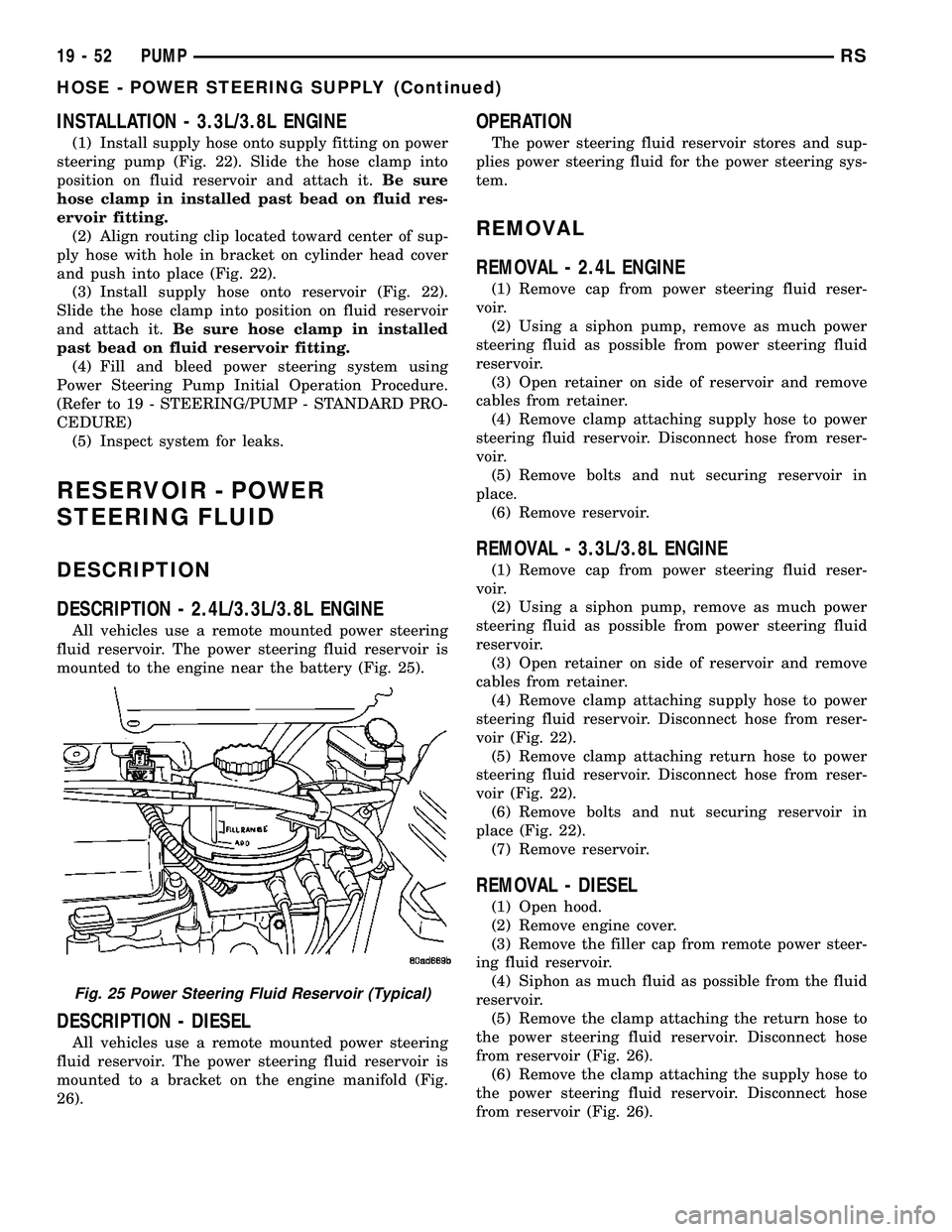
All vehicles use a remote mounted power steering
fluid reservoir. The power steering fluid reservoir is
mounted to the engine near the battery (Fig. 25).
DESCRIPTION - DIESEL
All vehicles use a remote mounted power steering
fluid reservoir. The power steering fluid reservoir is
mounted to a bracket on the engine manifold (Fig.
26).
OPERATION
The power steering fluid reservoir stores and sup-
plies power steering fluid for the power steering sys-
tem.
REMOVAL
REMOVAL - 2.4L ENGINE
(1) Remove cap from power steering fluid reser-
voir.
(2) Using a siphon pump, remove as much power
steering fluid as possible from power steering fluid
reservoir.
(3) Open retainer on side of reservoir and remove
cables from retainer.
(4) Remove clamp attaching supply hose to power
steering fluid reservoir. Disconnect hose from reser-
voir.
(5) Remove bolts and nut securing reservoir in
place.
(6) Remove reservoir.
REMOVAL - 3.3L/3.8L ENGINE
(1) Remove cap from power steering fluid reser-
voir.
(2) Using a siphon pump, remove as much power
steering fluid as possible from power steering fluid
reservoir.
(3) Open retainer on side of reservoir and remove
cables from retainer.
(4) Remove clamp attaching supply hose to power
steering fluid reservoir. Disconnect hose from reser-
voir (Fig. 22).
(5) Remove clamp attaching return hose to power
steering fluid reservoir. Disconnect hose from reser-
voir (Fig. 22).
(6) Remove bolts and nut securing reservoir in
place (Fig. 22).
(7) Remove reservoir.
REMOVAL - DIESEL
(1) Open hood.
(2) Remove engine cover.
(3) Remove the filler cap from remote power steer-
ing fluid reservoir.
(4) Siphon as much fluid as possible from the fluid
reservoir.
(5) Remove the clamp attaching the return hose to
the power steering fluid reservoir. Disconnect hose
from reservoir (Fig. 26).
(6) Remove the clamp attaching the supply hose to
the power steering fluid reservoir. Disconnect hose
from reservoir (Fig. 26).
Fig. 25 Power Steering Fluid Reservoir (Typical)
19 - 52 PUMPRS
HOSE - POWER STEERING SUPPLY (Continued)
Page 1791 of 2339
DESCRIPTION N´m Ft. Lbs. In. Lbs.
Sliding door glass nuts 3.4 Ð 30
Sliding door latch striker 28 21 Ð
Sliding door to roller arm bracket 12 9 Ð
Storage bin track guide to seat riser 3.5 Ð 31
Sunroof opening panel to lifter arm screws 5 44
Sunroof opening panel motor screws 4 35
Sunroof trough bracket to roof bolts 6 53
Sunroof trough to trough bracket bolts 6 53
Sunroof trough bracket bolts 6 53
Support cylinders to liftgate 28 21 Ð
BODY LUBRICATION
LUBRICATION REQUIREMENTS
Body mechanisms and linkages should be
inspected, cleaned, and lubricated, as required, to
maintain ease of operation and to provide protection
against rust and wear. When performing other under
hood services, the hood latch release mechanism and
safety catch should be inspected, cleaned, and lubri-
cated. During the winter season, external door lock
cylinders should be lubricated to assure proper oper-
ation when exposed to water and ice.
Prior to the application of any lubricant, the parts
concerned should be wiped clean to remove dust and
grit. If necessary, a suitable solvent can be used to
clean the item to be lubricated. After lubricating a
component, any excess oil or grease should be
removed.
LUBRICANT APPLICATION
DOOR LOCK CYLINDERS
(1) Apply a small amount of lubricant directly into
the lock cylinder.
(2) Apply a small amount of lubricant to the key.
(3) Insert key into lock cylinder and cycle the
mechanism from the locked to the unlocked position.
NOTE: Do not add more lubricant.
(4) Cycle the lock cylinder mechanism several
times to allow the lubricant to flow throughout the
cylinder.
(5) Wipe all lubricant from exterior of lock cylinder
and key.ALL OTHER BODY MECHANISMS
(1) Clean component as described above.
(2) Apply specified lubricant to all pivoting and
sliding contact areas of component.
LUBRICANT USAGE
ENGINE OIL
²Door Hinges ± Hinge Pin and Pivot Contact
Areas
²Hood Hinges ± Pivot Points
²Liftgate Hinges
MOPARTSPRAY WHITE LUBE OR EQUIVALENT
²Door Check Straps
²Liftgate Latches
²Liftgate Prop Pivots
²Ash Receiver
²Fuel Filler Door Remote Control Latch Mecha-
nism
²Parking Brake Mechanism
²Sliding Seat Tracks
²Liftgate Latch
MOPARTMultipurpose GREASE OR EQUIVALENT
²All Other Hood Mechanisms
MOPARTLOCK CYLINDER LUBRICANT OR
EQUIVALENT
²Door Lock Cylinders
²Liftgate Lock Cylinder
23 - 12 BODYRS
BODY (Continued)
Page 1829 of 2339
COWL GRILLE
REMOVAL
(1) Remove wiper arms. (Refer to 8 - ELECTRI-
CAL/WIPERS/WASHERS/WIPER ARMS -
REMOVAL)
(2) Remove four (4) screws securing cowl cover to
wiper module (Fig. 6).
(3) Disengage quarter turn fasteners at outboard
ends of cowl grill from body.
(4) Release hood latch and open hood.
CAUTION: To prevent hood scratching of cowl grille
before removal, cover outboard exterior ends of
cowl grille with masking tape or equivalent method.
NOTE: Do not over bend cowl grille during removal.
Bend cowl grille just enough to clear top of wiper
pivot shaft and bottom rear corner of hood.
(5) Remove cowl grill by raising above driver side
wiper pivot shaft and swinging away towards engine
compartment. The cowl grille will need to be bent onoutboard end to clear simultaneously top of wiper
pivot shaft and bottom corner of hood.
(6) Close hood. Do not latch. Remove outboard
screws. (Fig. 7).
(7) Disconnect washer hose in line connector.
(8) Disconnect washer hose and grommet from
hole in wiper module and pull out.
(9) Remove cowl grille by raising over opposite
wiper pivot shaft and removing away from vehicle.
(10) Remove cowl cover from vehicle.
INSTALLATION
(1) Reverse removal procedure.
(2) When installing cowl cover over wiper module,
make sure fore aft locator on the underside of cowl
grill seat into the locator grooves on top of wiper
module.
(3) Start all cowl grille mounting screws by hand
before torquing to specifications.
(4) Assure washer hose is properly routed and not
pinched.
(5) Center cowl grille to body and windshield.
(6) Assure ªarrowº indicator head of quarter turn
fasteners is pointing toward windshield.
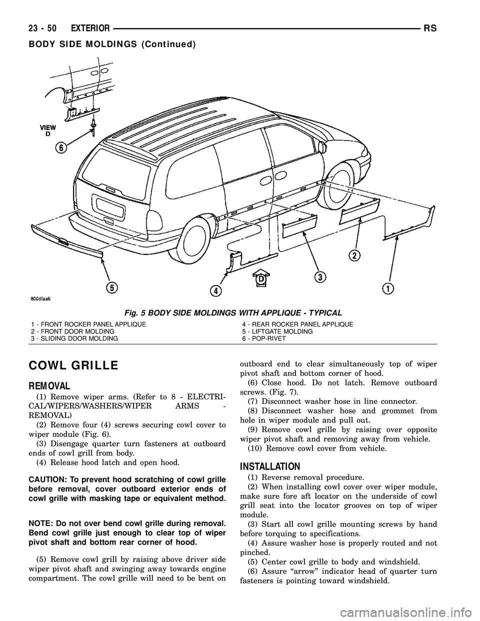
Fig. 5 BODY SIDE MOLDINGS WITH APPLIQUE - TYPICAL
1 - FRONT ROCKER PANEL APPLIQUE
2 - FRONT DOOR MOLDING
3 - SLIDING DOOR MOLDING4 - REAR ROCKER PANEL APPLIQUE
5 - LIFTGATE MOLDING
6 - POP-RIVET
23 - 50 EXTERIORRS
BODY SIDE MOLDINGS (Continued)
Page 1831 of 2339
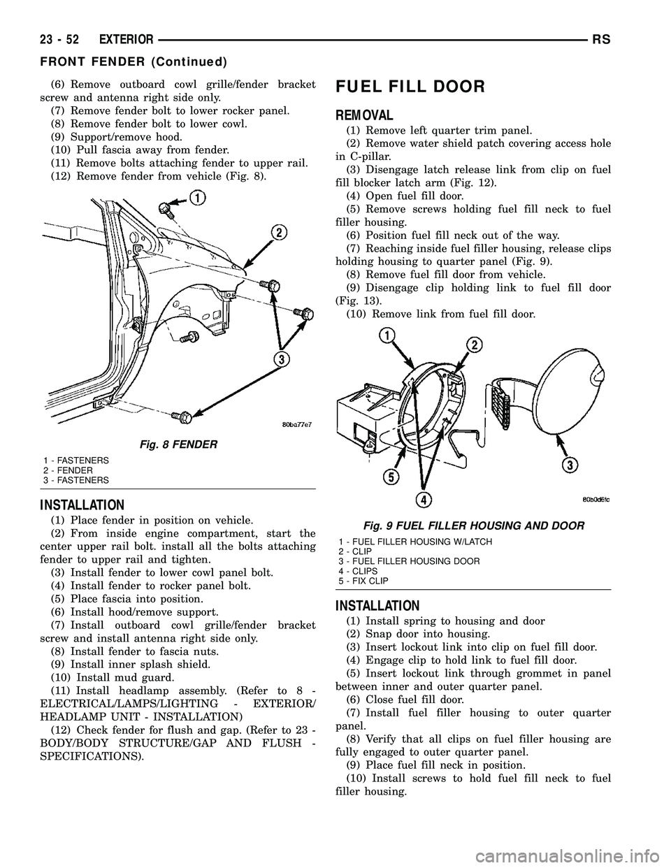
(6) Remove outboard cowl grille/fender bracket
screw and antenna right side only.
(7) Remove fender bolt to lower rocker panel.
(8) Remove fender bolt to lower cowl.
(9) Support/remove hood.
(10) Pull fascia away from fender.
(11) Remove bolts attaching fender to upper rail.
(12) Remove fender from vehicle (Fig. 8).
INSTALLATION
(1) Place fender in position on vehicle.
(2) From inside engine compartment, start the
center upper rail bolt. install all the bolts attaching
fender to upper rail and tighten.
(3) Install fender to lower cowl panel bolt.
(4) Install fender to rocker panel bolt.
(5) Place fascia into position.
(6) Install hood/remove support.
(7) Install outboard cowl grille/fender bracket
screw and install antenna right side only.
(8) Install fender to fascia nuts.
(9) Install inner splash shield.
(10) Install mud guard.
(11) Install headlamp assembly. (Refer to 8 -
ELECTRICAL/LAMPS/LIGHTING - EXTERIOR/
HEADLAMP UNIT - INSTALLATION)
(12) Check fender for flush and gap. (Refer to 23 -
BODY/BODY STRUCTURE/GAP AND FLUSH -
SPECIFICATIONS).
FUEL FILL DOOR
REMOVAL
(1) Remove left quarter trim panel.
(2) Remove water shield patch covering access hole
in C-pillar.
(3) Disengage latch release link from clip on fuel
fill blocker latch arm (Fig. 12).
(4) Open fuel fill door.
(5) Remove screws holding fuel fill neck to fuel
filler housing.
(6) Position fuel fill neck out of the way.
(7) Reaching inside fuel filler housing, release clips
holding housing to quarter panel (Fig. 9).
(8) Remove fuel fill door from vehicle.
(9) Disengage clip holding link to fuel fill door
(Fig. 13).
(10) Remove link from fuel fill door.
INSTALLATION
(1) Install spring to housing and door
(2) Snap door into housing.
(3) Insert lockout link into clip on fuel fill door.
(4) Engage clip to hold link to fuel fill door.
(5) Insert lockout link through grommet in panel
between inner and outer quarter panel.
(6) Close fuel fill door.
(7) Install fuel filler housing to outer quarter
panel.
(8) Verify that all clips on fuel filler housing are
fully engaged to outer quarter panel.
(9) Place fuel fill neck in position.
(10) Install screws to hold fuel fill neck to fuel
filler housing.
Fig. 8 FENDER
1 - FASTENERS
2 - FENDER
3 - FASTENERS
Fig. 9 FUEL FILLER HOUSING AND DOOR
1 - FUEL FILLER HOUSING W/LATCH
2 - CLIP
3 - FUEL FILLER HOUSING DOOR
4 - CLIPS
5 - FIX CLIP
23 - 52 EXTERIORRS
FRONT FENDER (Continued)