2005 CHRYSLER CARAVAN open hood
[x] Cancel search: open hoodPage 2218 of 2339
DIAGNOSIS AND TESTING
REFRIGERANT SYSTEM LEAKS
WARNING: R-134a SERVICE EQUIPMENT OR VEHI-
CLE A/C SYSTEM SHOULD NOT BE PRESSURE
TESTED OR LEAK TESTED WITH COMPRESSED
AIR. MIXTURE OF AIR and R-134a CAN BE COMBUS-
TIBLE AT ELEVATED PRESSURES. THESE MIX-
TURES ARE POTENTIALLY DANGEROUS AND MAY
RESULT IN FIRE OR EXPLOSION CAUSING INJURY
OR PROPERTY DAMAGE.
AVOID BREATHING A/C REFRIGERANT AND LUBRI-
CANT VAPOR OR MIST. EXPOSURE MAY IRRITATE
EYES, NOSE AND THROAT. USE ONLY APPROVED
SERVICE EQUIPMENT MEETING SAE REQUIRE-
MENTS TO DISCHARGE R-134a SYSTEM. IF ACCI-
DENTAL SYSTEM DISCHARGE OCCURS, VENTILATE
WORK AREA BEFORE RESUMING SERVICE.
If the A/C system is not cooling properly, determine
if the refrigerant system is fully charged with R-134a
(Refer to 24 - HEATING & AIR CONDITIONING/
PLUMBING - FRONT/REFRIGERANT - DIAGNO-
SIS AND TESTING - REFRIGERANT SYSTEM
CHARGE LEVEL). If while performing this test A/C
liquid line pressure is less than 345 kPa (50 psi) pro-
ceed to System Empty procedure. If liquid line pres-
sure is greater than 345 kPa (50 psi) proceed to
System Low procedure. If the refrigerant system is
empty or low in refrigerant charge, a leak at any line
fitting or component seal is likely. A review of the fit-
tings, lines and components for oily residue is an
indication of the leak location.
To detect a leak in the refrigerant system, perform
one of the following procedures as indicated by the
results of the refrigerant system charge level test.
SYSTEM EMPTY
(1) Evacuate the refrigerant system to the lowest
degree of vacuum possible (approx. 28 in Hg.) (Refer
to 24 - HEATING & AIR CONDITIONING/PLUMB-
ING - FRONT/REFRIGERANT - STANDARD PRO-
CEDURE - REFRIGERANT SYSTEM EVACUATE).
Determine if the system holds a vacuum for 15 min-
utes. If vacuum is held, a leak is probably not
present. If system will not maintain vacuum level,
proceed with this procedure.
(2) Prepare a 0.284 Kg. (10 oz.) refrigerant charge
to be injected into the system.
(3) Connect and dispense 0.284 Kg. (10 oz.) of
refrigerant into the evacuated refrigerant system
(Refer to 24 - HEATING & AIR CONDITIONING/
PLUMBING - FRONT/REFRIGERANT - STANDARD
PROCEDURE - REFRIGERANT SYSTEM CHARGE).
(4) Proceed to the SYSTEM LOW procedures.SYSTEM LOW
(1) Position the vehicle in a wind-free work area.
This will aid in detecting small leaks.
(2) Bring the refrigerant system up to operating
temperature and pressure. This is done by allowing
the engine to run for five minutes with the system
set to the following:
²Transaxle in Park
²Engine idling
²Rear A/C Off (if equipped)
²A/C controls set to 100 percent outside air
²Blower switch in the highest speed position
²A/C in the ON position
²Front windows open
CAUTION: A leak detector designed for R-12 refrig-
erant (only) will not detect leaks in a R-134a refrig-
erant system.
(3) Shut off the vehicle and wait 2 to 7 minutes.
Then use an Electronic Leak Detector that is
designed to detect R-134a type refrigerant and search
for leaks. Fittings, lines, or components that appear
to be oily usually indicates a refrigerant leak. To
inspect the evaporator core for leaks, insert the leak
detector probe into the drain tube opening or a heat
duct. A R-134a dye is available to aid in leak detec-
tion, use only DaimlerChrysler approved refrigerant
dye.
SYSTEM CHARGE LEVEL TEST
WARNING: REFER TO THE APPLICABLE WARN-
INGS AND CAUTIONS FOR THIS SYSTEM BEFORE
PERFORMING THE FOLLOWING OPERATION (Refer
to 24 - HEATING & AIR CONDITIONING/PLUMBING -
FRONT - WARNING - A/C PLUMBING) and (Refer to
24 - HEATING & AIR CONDITIONING/PLUMBING -
FRONT - CAUTION - A/C PLUMBING).
NOTE: Always refer to the underhood HVAC Speci-
fication Label for the refrigerant fill specification of
the vehicle being serviced.
The procedure that follows should be used to deter-
mine whether the refrigerant system contains the
proper refrigerant charge. Symptoms of an improper
refrigerant charge (low) include: poor air conditioner
performance, fog emitted from the air conditioner
outlets, a hissing sound from the expansion valve/
evaporator area. There are two different methods
with which the refrigerant charge level may be
tested:
1. Using a DRBIIItscan tool, a thermocouple and
the Charge Determination Chart (Fig. 1). Refer to
the appropriate diagnostic information.
RSPLUMBING - FRONT24-67
PLUMBING - FRONT (Continued)
Page 2222 of 2339
If a compressor designed to use R-134a refrigerant
is left open to the atmosphere for an extended period
of time. It is recommended that the refrigerant oil be
drained and replaced with new oil or a new compres-
sor be used. This will eliminate the possibility of con-
taminating the refrigerant system.
If the refrigerant system has been open to the
atmosphere, it must be evacuated before the system
can be filled. Moisture and air mixed with the refrig-
erant will raise the compressor head pressure above
acceptable operating levels. This will reduce the per-
formance of the air conditioner and damage the com-
pressor. Moisture will boil at near room temperature
when exposed to vacuum. A R-134a refrigerant recov-
ery/recycling/charging station that meets SAE Stan-
dard J2210 must be used to evacuate the refrigerant
system. See the operating instructions supplied by
the equipment manufacturer for proper care and use
of this equipment. To evacuate the refrigerant sys-
tem, use the following procedure:
NOTE: When connecting the service equipment
couplings to the refrigerant system service ports,
be certain that the valve of each coupling is fully
closed. This will reduce the amount of effort
required to make the connection.
(1) Recover the refrigerant system (Refer to 24 -
HEATING & AIR CONDITIONING/PLUMBING -
STANDARD PROCEDURE).
(2) Connect a suitable charging station, refrigerant
recovery machine or a manifold gauge set with vac-
uum pump and refrigerant recovery equipment.
(3) Open the suction and discharge valves and
start the vacuum pump. The vacuum pump should
run a minimum of 45 minutes prior to charge to
eliminate all moisture in system. When the suction
gauge reads -88 kPa (-26 in. Hg) vacuum or greater
for 30 minutes, close all valves and turn off vacuum
pump. If the system fails to reach specified vacuum,
the refrigerant system likely has a leak that must be
corrected. If the refrigerant system maintains speci-
fied vacuum for at least 30 minutes, start the vac-
uum pump, open the suction and discharge valves.
Then allow the system to evacuate an additional 10
minutes.
(4) Close all valves. Turn off and disconnect the
vacuum pump.
(5) Charge the refrigerant system (Refer to 24 -
HEATING & AIR CONDITIONING/PLUMBING -
STANDARD PROCEDURE).REFRIGERANT SYSTEM CHARGE
WARNING: REFER TO THE APPLICABLE WARN-
INGS AND CAUTIONS FOR THIS SYSTEM BEFORE
PERFORMING THE FOLLOWING OPERATION (Refer
to 24 - HEATING & AIR CONDITIONING/PLUMBING -
FRONT - WARNING - A/C PLUMBING) and (Refer to
24 - HEATING & AIR CONDITIONING/PLUMBING -
FRONT - CAUTION - A/C PLUMBING).
After all refrigerant system leaks have been
repaired and the refrigerant system has been evacu-
ated, a refrigerant charge can be injected into the
system. For the proper amount of the refrigerant
charge, refer to REFRIGERANT CHARGE CAPAC-
ITY. A R-134a refrigerant recovery/recycling/charging
station that meets SAE Standard J2210 must be
used to charge the refrigerant system with R-134a
refrigerant. See the operating instructions supplied
by the equipment manufacturer for proper care and
use of this equipment.
REFRIGERANT CHARGE CAPACITY
NOTE: Always refer to the underhood HVAC Speci-
fication Label for the refrigerant fill specification of
the vehicle being serviced.
CHARGING PROCEDURE
CAUTION: A small amount of refrigerant oil is
removed from the A/C system each time the refrig-
erant system is recovered and evacuated. Before
charging the A/C system, you MUST replenish any
oil lost during the recovery process. Refer the
equipment manufacturer instructions for more infor-
mation.
(1) Evacuate the refrigerant system. (Refer to 24 -
HEATING & AIR CONDITIONING/PLUMBING -
FRONT/REFRIGERANT - STANDARD PROCE-
DURE - REFRIGERANT SYSTEM EVACUATE).
(2) A manifold gauge set and a R-134a refrigerant
recovery/recycling/charging station that meets SAE
Standard J2210 should still be connected to the
refrigerant system.
(3) Measure the proper amount of refrigerant and
heat it to 52É C (125É F) with the charging station.
See the operating instructions supplied by the equip-
ment manufacturer for proper use of this equipment.
RSPLUMBING - FRONT24-71
PLUMBING - FRONT (Continued)
Page 2227 of 2339
REMOVAL
2.4L/3.3L/3.8L ENGINES
WARNING: REFER TO THE APPLICABLE WARN-
INGS AND CAUTIONS FOR THIS SYSTEM BEFORE
PERFORMING THE FOLLOWING OPERATION (Refer
to 24 - HEATING & AIR CONDITIONING/PLUMBING -
FRONT - WARNING - A/C PLUMBING) and (Refer to
24 - HEATING & AIR CONDITIONING/PLUMBING -
FRONT - CAUTION - A/C PLUMBING).
NOTE: Before removing the A/C condenser, note the
location of each of the radiator and condenser air
seals. These air seals are used to direct air through
the A/C condenser and radiator. The air seals must
be reinstalled in their proper locations in order for
the A/C and engine cooling systems to perform as
designed.
(1) Recover the refrigerant from the refrigerant
system (Refer to 24 - HEATING & AIR CONDITION-
ING/PLUMBING - FRONT/REFRIGERANT - STAN-
DARD PROCEDURE - REFRIGERANT SYSTEM
RECOVERY).
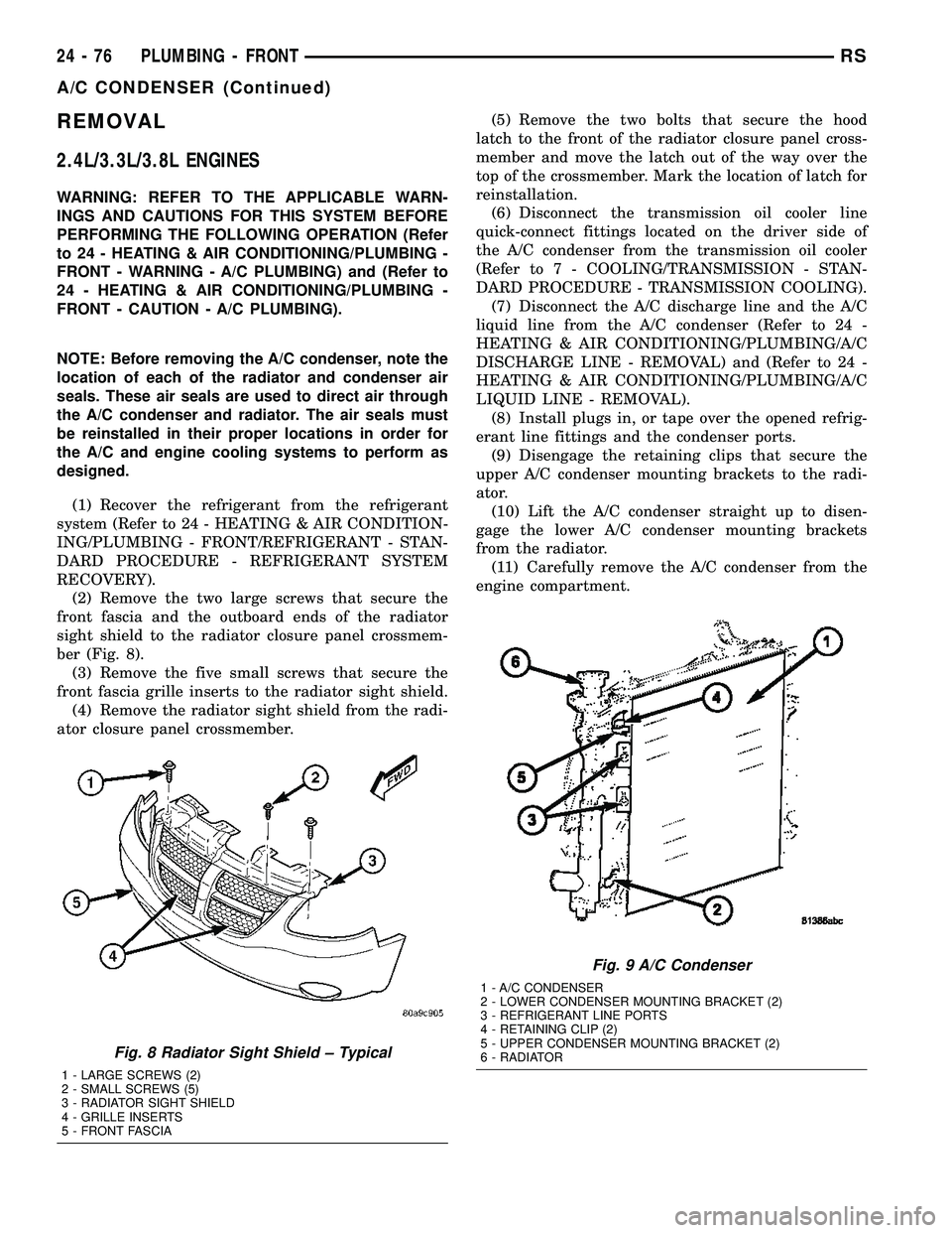
(2) Remove the two large screws that secure the
front fascia and the outboard ends of the radiator
sight shield to the radiator closure panel crossmem-
ber (Fig. 8).
(3) Remove the five small screws that secure the
front fascia grille inserts to the radiator sight shield.
(4) Remove the radiator sight shield from the radi-
ator closure panel crossmember.(5) Remove the two bolts that secure the hood
latch to the front of the radiator closure panel cross-
member and move the latch out of the way over the
top of the crossmember. Mark the location of latch for
reinstallation.
(6) Disconnect the transmission oil cooler line
quick-connect fittings located on the driver side of
the A/C condenser from the transmission oil cooler
(Refer to 7 - COOLING/TRANSMISSION - STAN-
DARD PROCEDURE - TRANSMISSION COOLING).
(7) Disconnect the A/C discharge line and the A/C
liquid line from the A/C condenser (Refer to 24 -
HEATING & AIR CONDITIONING/PLUMBING/A/C
DISCHARGE LINE - REMOVAL) and (Refer to 24 -
HEATING & AIR CONDITIONING/PLUMBING/A/C
LIQUID LINE - REMOVAL).
(8) Install plugs in, or tape over the opened refrig-
erant line fittings and the condenser ports.
(9) Disengage the retaining clips that secure the
upper A/C condenser mounting brackets to the radi-
ator.
(10) Lift the A/C condenser straight up to disen-
gage the lower A/C condenser mounting brackets
from the radiator.
(11) Carefully remove the A/C condenser from the
engine compartment.
Fig. 8 Radiator Sight Shield ± Typical
1 - LARGE SCREWS (2)
2 - SMALL SCREWS (5)
3 - RADIATOR SIGHT SHIELD
4 - GRILLE INSERTS
5 - FRONT FASCIA
Fig. 9 A/C Condenser
1 - A/C CONDENSER
2 - LOWER CONDENSER MOUNTING BRACKET (2)
3 - REFRIGERANT LINE PORTS
4 - RETAINING CLIP (2)
5 - UPPER CONDENSER MOUNTING BRACKET (2)
6 - RADIATOR
24 - 76 PLUMBING - FRONTRS
A/C CONDENSER (Continued)
Page 2228 of 2339
2.5L/2.8L DIESEL ENGINES
WARNING: REFER TO THE APPLICABLE WARN-
INGS AND CAUTIONS FOR THIS SYSTEM BEFORE
PERFORMING THE FOLLOWING OPERATION (Refer
to 24 - HEATING & AIR CONDITIONING/PLUMBING -
FRONT - WARNING - A/C PLUMBING) and (Refer to
24 - HEATING & AIR CONDITIONING/PLUMBING -
FRONT - CAUTION - A/C PLUMBING).
NOTE: Before removing the A/C condenser, note the
location of each of the radiator and condenser air
seals. These air seals are used to direct air through
the A/C condenser and radiator. The air seals must
be reinstalled in their proper locations in order for
the A/C and engine cooling systems to perform as
designed.
(1) Recover the refrigerant from the refrigerant
system (Refer to 24 - HEATING & AIR CONDITION-
ING/PLUMBING - FRONT/REFRIGERANT - STAN-
DARD PROCEDURE - REFRIGERANT SYSTEM
RECOVERY).
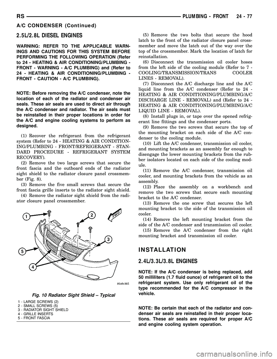
(2) Remove the two large screws that secure the
front fascia and the outboard ends of the radiator
sight shield to the radiator closure panel crossmem-
ber (Fig. 8).
(3) Remove the five small screws that secure the
front fascia grille inserts to the radiator sight shield.
(4) Remove the radiator sight shield from the radi-
ator closure panel crossmember.(5) Remove the two bolts that secure the hood
latch to the front of the radiator closure panel cross-
member and move the latch out of the way over the
top of the crossmember. Mark the location of latch for
reinstallation.
(6) Disconnect the transmission oil cooler hoses
from the left side of the cooling module (Refer to 7 -
COOLING/TRANSMISSION/TRANS COOLER
LINES - REMOVAL).
(7) Disconnect the A/C discharge line and the A/C
liquid line from the A/C condenser (Refer to 24 -
HEATING & AIR CONDITIONING/PLUMBING/A/C
DISCHARGE LINE - REMOVAL) and (Refer to 24 -
HEATING & AIR CONDITIONING/PLUMBING/A/C
LIQUID LINE - REMOVAL).
(8) Install plugs in, or tape over the opened refrig-
erant line fittings and the condenser ports.
(9) Remove the two screws that secure the top of
the mounting bracket on each side of the A/C con-
denser to the cooling module.
(10) Lift the A/C condenser, transmission oil cooler,
and mounting brackets as an assembly far enough to
disengage the lower mounting brackets from the rub-
ber isolators located on each side of the cooling mod-
ule.
(11) Remove the A/C condenser, transmission oil
cooler, and mounting brackets from the vehicle as an
assembly.
(12) Place the assembly on a workbench and
remove the two screws that secure each mounting
bracket to the A/C condenser.
(13) Remove the one screw that secures the left
mounting bracket to the side of the transmission oil
cooler.
(14) Remove the left mounting bracket from the
side of the A/C condenser and transmission oil cooler.
(15) Remove the A/C condenser from the right
mounting bracket and transmission oil cooler.
INSTALLATION
2.4L/3.3L/3.8L ENGINES
NOTE: If the A/C condenser is being replaced, add
50 milliliters (1.7 fluid ounce) of refrigerant oil to the
refrigerant system. Use only refrigerant oil of the
type recommended for the A/C compressor in the
vehicle.
NOTE: Be certain that each of the radiator and con-
denser air seals are reinstalled in their proper loca-
tions. These air seals are required for proper A/C
and engine cooling system operation.
Fig. 10 Radiator Sight Shield ± Typical
1 - LARGE SCREWS (2)
2 - SMALL SCREWS (5)
3 - RADIATOR SIGHT SHIELD
4 - GRILLE INSERTS
5 - FRONT FASCIA
RSPLUMBING - FRONT24-77
A/C CONDENSER (Continued)
Page 2229 of 2339

(1) Position the A/C condenser into the engine
compartment.
(2) Carefully lower the A/C condenser straight
down to engage the lower mounting brackets to the
radiator.
(3) Engage the upper A/C condenser mounting
brackets to the radiator. Be sure that the upper
retaining clips are fully engaged to the upper mount-
ing brackets.
(4) Remove the tape or plugs from the opened
refrigerant line fittings and the condenser ports.
(5) Connect the A/C discharge line and the A/C liq-
uid line to the A/C condenser (Refer to 24 - HEAT-
ING & AIR CONDITIONING/PLUMBING/A/C
DISCHARGE LINE - INSTALLATION) and (Refer to
24 - HEATING & AIR CONDITIONING/PLUMBING/
A/C LIQUID LINE - INSTALLATION).
(6) Connect the transmission oil cooler lines to the
A/C Condenser. Be sure that the quick-connect fit-
tings are fully engaged to the cooler tapping block
(Refer to 7 - COOLING/TRANSMISSION - STAN-
DARD PROCEDURE - TRANSMISSION COOLING).
(7) Position the hood latch onto the front of the
radiator closure panel crossmember.
(8) Install the two screws that secure the hood
latch to the crossmember. Check and adjust the hoodlatch as required. Tighten the bolts to 14 N´m (123
in. lbs.).
(9) Position the radiator sight shield onto the radi-
ator closure panel crossmember.
(10) Install the five small screws that secure the
front fascia grille inserts to the radiator sight shield.
Tighten the screws to 2 N´m (17 in. lbs.).
(11) Install the two large screws that secure the
front fascia and the outboard ends of the radiator
sight shield to the radiator closure panel crossmem-
ber. Tighten the screws to 6 N´m (53 in. lbs.).
(12) Evacuate the refrigerant system (Refer to 24 -
HEATING & AIR CONDITIONING/PLUMBING -
FRONT/REFRIGERANT - STANDARD PROCE-
DURE - REFRIGERANT SYSTEM EVACUATE).
(13) Charge the refrigerant system (Refer to 24 -
HEATING & AIR CONDITIONING/PLUMBING -
FRONT/REFRIGERANT - STANDARD PROCE-
DURE - REFRIGERANT SYSTEM CHARGE).
2.5L/2.8L DIESEL ENGINES
NOTE: If the A/C condenser is being replaced, add
50 milliliters (1.7 fluid ounce) of refrigerant oil to the
refrigerant system. Use only refrigerant oil of the
type recommended for the A/C compressor in the
vehicle.
NOTE: Be certain that each of the radiator and con-
denser air seals are reinstalled in their proper loca-
tions. These air seals are required for proper A/C
and engine cooling system operation.
(1) Position the A/C condenser onto the right
mounting bracket and transmission oil cooler unit.
(2) Position the left mounting bracket onto the side
of the A/C condenser and transmission oil cooler.
(3) Install the screw that secures the left mounting
bracket to the side of the transmission oil cooler.
Tighten the screw to 5 N´m (45 in. lbs.).
(4) Install the two screws that secure each mount-
ing bracket to the sides of the A/C condenser. Tighten
the screws to 5 N´m (45 in. lbs.).
NOTE: Verify that the A/C condenser isolators are
all installed and positioned correctly.
(5) Position the A/C condenser, transmission oil
cooler, and mounting brackets into the vehicle as an
assembly. Be certain that the lower mounting brack-
ets are engaged into the rubber isolators located on
each side of the cooling module.
(6) Install the two screws that secure the top of
the mounting bracket on each side of the A/C con-
denser to the cooling module. Tighten the screws to 5
N´m (45 in. lbs.).
Fig. 11 A/C Condenser ± 2.5L/2.8L Diesel Engines
1 - BOLT (2)
2 - LOWER MOUNT ISOLATOR (2)
3 - A/C CONDENSER
24 - 78 PLUMBING - FRONTRS
A/C CONDENSER (Continued)
Page 2230 of 2339
(7) Remove the tape or plugs from the opened
refrigerant line fittings and the condenser ports.
(8) Connect the A/C discharge line and the A/C liq-
uid line to the A/C condenser (Refer to 24 - HEAT-
ING & AIR CONDITIONING/PLUMBING/A/C
DISCHARGE LINE - INSTALLATION) and (Refer to
24 - HEATING & AIR CONDITIONING/PLUMBING/
A/C LIQUID LINE - INSTALLATION).
(9) Reconnect the hoses to the transmission oil
cooler fittings on the left side of the cooling module
(Refer to 7 - COOLING/TRANSMISSION/TRANS
COOLER LINES - INSTALLATION).
(10) Reposition the hood latch to the front of the
radiator closure panel crossmember.
(11) Install the two screws that secure the hood
latch to the front of the radiator closure panel cross-
member. Check and adjust the hood latch as needed.
Tighten the screws to 14 N´m (123 in. lbs.).
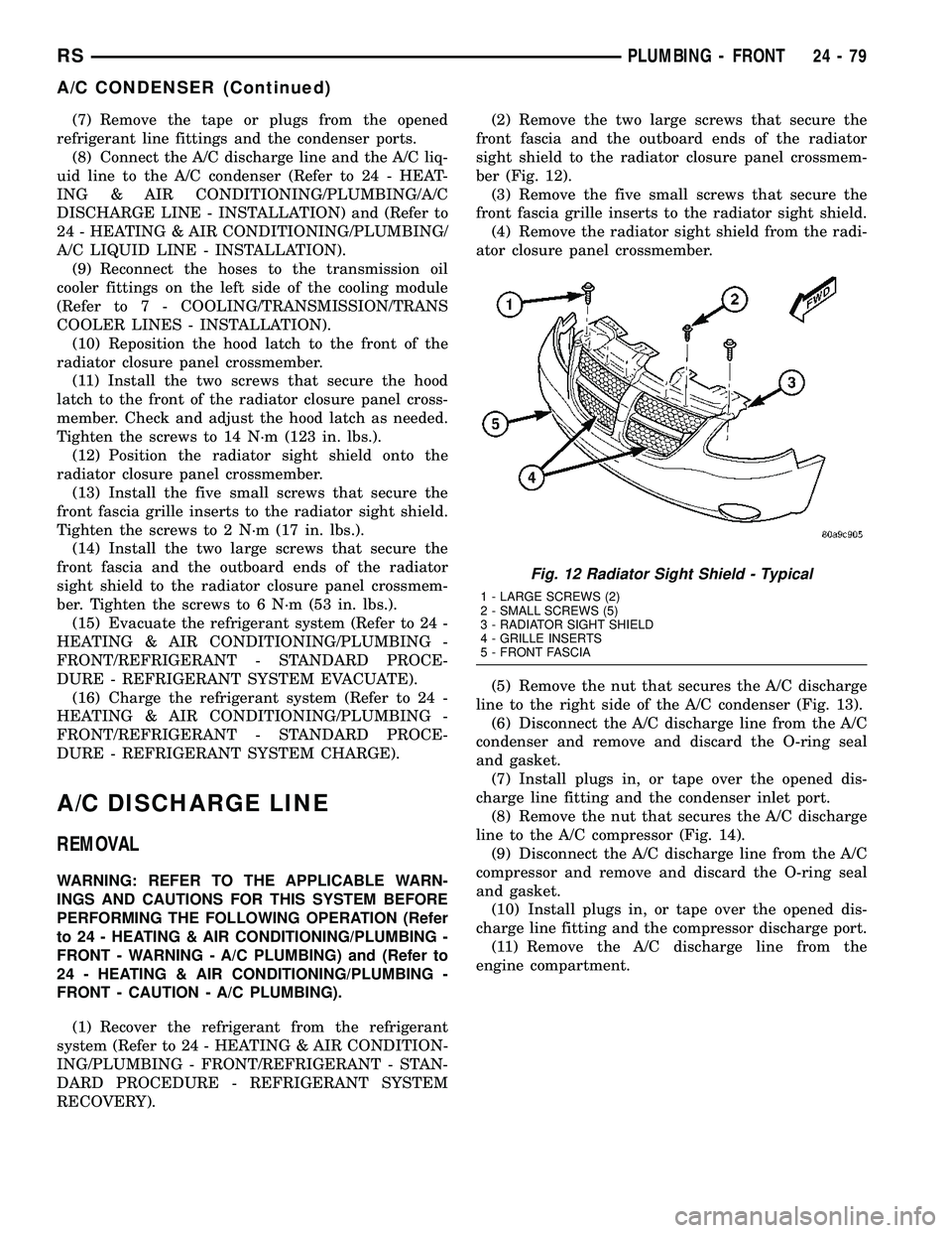
(12) Position the radiator sight shield onto the
radiator closure panel crossmember.
(13) Install the five small screws that secure the
front fascia grille inserts to the radiator sight shield.
Tighten the screws to 2 N´m (17 in. lbs.).
(14) Install the two large screws that secure the
front fascia and the outboard ends of the radiator
sight shield to the radiator closure panel crossmem-
ber. Tighten the screws to 6 N´m (53 in. lbs.).
(15) Evacuate the refrigerant system (Refer to 24 -
HEATING & AIR CONDITIONING/PLUMBING -
FRONT/REFRIGERANT - STANDARD PROCE-
DURE - REFRIGERANT SYSTEM EVACUATE).
(16) Charge the refrigerant system (Refer to 24 -
HEATING & AIR CONDITIONING/PLUMBING -
FRONT/REFRIGERANT - STANDARD PROCE-
DURE - REFRIGERANT SYSTEM CHARGE).
A/C DISCHARGE LINE
REMOVAL
WARNING: REFER TO THE APPLICABLE WARN-
INGS AND CAUTIONS FOR THIS SYSTEM BEFORE
PERFORMING THE FOLLOWING OPERATION (Refer
to 24 - HEATING & AIR CONDITIONING/PLUMBING -
FRONT - WARNING - A/C PLUMBING) and (Refer to
24 - HEATING & AIR CONDITIONING/PLUMBING -
FRONT - CAUTION - A/C PLUMBING).
(1) Recover the refrigerant from the refrigerant
system (Refer to 24 - HEATING & AIR CONDITION-
ING/PLUMBING - FRONT/REFRIGERANT - STAN-
DARD PROCEDURE - REFRIGERANT SYSTEM
RECOVERY).(2) Remove the two large screws that secure the
front fascia and the outboard ends of the radiator
sight shield to the radiator closure panel crossmem-
ber (Fig. 12).
(3) Remove the five small screws that secure the
front fascia grille inserts to the radiator sight shield.
(4) Remove the radiator sight shield from the radi-
ator closure panel crossmember.
(5) Remove the nut that secures the A/C discharge
line to the right side of the A/C condenser (Fig. 13).
(6) Disconnect the A/C discharge line from the A/C
condenser and remove and discard the O-ring seal
and gasket.
(7) Install plugs in, or tape over the opened dis-
charge line fitting and the condenser inlet port.
(8) Remove the nut that secures the A/C discharge
line to the A/C compressor (Fig. 14).
(9) Disconnect the A/C discharge line from the A/C
compressor and remove and discard the O-ring seal
and gasket.
(10) Install plugs in, or tape over the opened dis-
charge line fitting and the compressor discharge port.
(11) Remove the A/C discharge line from the
engine compartment.
Fig. 12 Radiator Sight Shield - Typical
1 - LARGE SCREWS (2)
2 - SMALL SCREWS (5)
3 - RADIATOR SIGHT SHIELD
4 - GRILLE INSERTS
5 - FRONT FASCIA
RSPLUMBING - FRONT24-79
A/C CONDENSER (Continued)
Page 2332 of 2339
STORAGE BIN GUIDE - INSTALLATION,UNDER SEAT ....................... 23-150
STORAGE BIN GUIDE - REMOVAL, UNDER SEAT ....................... 23-150
STORAGE BIN LOCK/LATCH - INSTALLATION, UNDER SEAT ..........23-150
STORAGE BIN LOCK/LATCH - REMOVAL, UNDER SEAT ....................... 23-150
STRAP - INSTALLATION, CHECK .........23-15
STRAP - INSTALLATION, FRONT SEAT BACK ASSIST ...................... 23-112
STRAP - REMOVAL, CHECK ............23-15
STRAP - REMOVAL, FRONT SEAT BACK ASSIST ........................... 23-112
STRAP - THIRD ROW - FOLD-IN-FLOOR - INSTALLATION, SEAT BACKSTOW .....23-158
STRAP - THIRD ROW - FOLD-IN-FLOOR - REMOVAL, SEAT BACKSTOW .........23-158
STRIKER - INSTALLATION, CENTER ......23-28
STRIKER - INSTALLATION, FUEL FILL DOOR BLOCKER LATCH ...............23-53
STRIKER - INSTALLATION, GLOVE BOX LATCH ............................. 23-66
STRIKER - INSTALLATION, HOLD OPEN LATCH ............................. 23-26
STRIKER - INSTALLATION, LATCH . . 23-19,23-42, 23-64
STRIKER - INSTALLATION, REAR LATCH . . 23-29
STRIKER - REMOVAL, CENTER ..........23-28
STRIKER - REMOVAL, FUEL FILL DOOR BLOCKER LATCH ..................... 23-53
STRIKER - REMOVAL, GLOVE BOX LATCH ............................. 23-66
STRIKER - REMOVAL, HOLD OPEN LATCH ............................. 23-26
STRIKER - REMOVAL, LATCH . 23-19,23-41,23-64
STRIKER - REMOVAL, REAR LATCH ......23-29
STRIPPED THREAD REPAIR - STANDARD PROCEDURE, MANIFOLD ..............9-147
STRUCTURAL ADHESIVE LOCATIONS - FOLD-IN-FLOOR ONLY -
SPECIFICATIONS .................... 23-228
STRUCTURAL ADHESIVE LOCATIONS - SPECIFICATIONS .................... 23-218
STRUCTURAL COLLAR - INSTALLATION ....9-49
STRUCTURAL COLLAR - REMOVAL .......9-49
STRUT - SECOND ROW - FOLD-IN- FLOOR - INSTALLATION, SEAT GAS .....23-139
STRUT - SECOND ROW - FOLD-IN- FLOOR - REMOVAL, SEAT GAS .........23-138
STRUT ASSEMBLY - ASSEMBLY ..........2-23
STRUT ASSEMBLY - DESCRIPTION .......2-19
STRUT ASSEMBLY - DIAGNOSIS AND TESTING ............................ 2-20
STRUT ASSEMBLY - DISASSEMBLY .......2-21
STRUT ASSEMBLY - INSTALLATION .......2-25
STRUT ASSEMBLY - OPERATION .........2-19
STRUT ASSEMBLY - REMOVAL ...........2-20
STUDS - FRONT - INSTALLATION, WHEEL MOUNTING ................... 22-21
STUDS - FRONT - REMOVAL, WHEEL MOUNTING ......................... 22-21
STUDS - REAR - INSTALLATION, WHEEL MOUNTING ......................... 22-22
STUDS - REAR - REMOVAL, WHEEL MOUNTING ......................... 22-22
SUCTION LINE - INSTALLATION . . . 24-107,24-97
SUCTION LINE - REMOVAL .......24-106,24-96
SUN VISOR - INSTALLATION ...........23-99
SUN VISOR - REMOVAL ...............23-99
SUN VISOR SUPPORT - INSTALLATION . . . 23-99
SUN VISOR SUPPORT - REMOVAL .......23-99
SUNROOF - DESCRIPTION ............23-169
SUNROOF ASSEMBLY - INSTALLATION . . 23-173
SUNROOF ASSEMBLY - REMOVAL ......23-173
SUNROOF DIAGNOSIS AND TESTING, DIAGNOSIS AND TESTING ............23-169
SUNROOF GLASS PANEL ADJUSTMENT, ADJUSTMENTS ..................... 23-173
SUNROOF MOTOR - INSTALLATION .....23-174
SUNROOF MOTOR - REMOVAL .........23-174
SUNROOF SWITCH - INSTALLATION .....23-176
SUNROOF SWITCH - REMOVAL ........23-176
SUNSHADE - INSTALLATION ...........23-173
SUNSHADE - REMOVAL ..............23-173
SUPPLEMENTAL CABIN HEATER, DIAGNOSIS AND TESTING ............24-114SUPPLY - PCM OUTPUT - OPERATION, 5
VOLT .............................. 8E-15
SUPPORT - INSTALLATION, LUMBAR ....23-150
SUPPORT - INSTALLATION, SUN VISOR . . . 23-99
SUPPORT - REMOVAL, LUMBAR .......23-150
SUPPORT - REMOVAL, SUN VISOR ......23-99
SUPPORT CYLINDER - INSTALLATION ....23-43
SUPPORT CYLINDER - REMOVAL ........23-42
SUPPORT PLATE - DRUM BRAKE - INSTALLATION ........................ 5-61
SUPPORT PLATE - DRUM BRAKE - REMOVAL ........................... 5-61
SUPPRESSION COMPONENTS - DESCRIPTION, RADIO NOISE ...........8A-15
SUPPRESSION COMPONENTS - OPERATION, RADIO NOISE .............8A-15
SURFACE PREPARATION - STANDARD PROCEDURE, ENGINE GASKET .......9-11,9-87
SUSPENSION - DESCRIPTION, FRONT ......2-2
SUSPENSION - DESCRIPTION, REAR ......2-26
SUSPENSION - OPERATION, FRONT ........2-2
SUSPENSION AND STEERING - DIAGNOSIS AND TESTING ..............2-50
SUSPENSION FASTENER TORQUE, SPECIFICATIONS - FRONT ................2-3
SUSPENSION FASTENER TORQUE, SPECIFICATIONS - REAR ................2-28
SUSPENSION, SPECIAL TOOLS - FRONT ....2-3
SUSPENSION, SPECIAL TOOLS - REAR ....2-28
SWITCH - DESCRIPTION .................8P-5
SWITCH - DESCRIPTION, B-PILLAR ......8N-52
SWITCH - DESCRIPTION, BRAKE FLUID LEVEL .............................. 5-10
SWITCH - DESCRIPTION, BRAKE LAMP ....8L-4
SWITCH - DESCRIPTION, EXTERIOR HANDLE ........................... 8N-10
SWITCH - DESCRIPTION, FULL OPEN ....8N-11,
8N-52
SWITCH - DESCRIPTION, HEATED SEAT . . . 8G-8
SWITCH - DESCRIPTION, HORN ..........8H-4
SWITCH - DESCRIPTION, MEMORY ......8N-36
SWITCH - DESCRIPTION, OIL PRESSURE . 9-144
SWITCH - DESCRIPTION, REAR WINDOW DEFOGGER .................. 8G-4
SWITCH - DESCRIPTION, REAR WIPER/WASHER ..................... 8R-10
SWITCH - DESCRIPTION, SEAT .........8N-34
SWITCH - DIAGNOSIS AND TESTING, BRAKE LAMP ........................ 8L-4
SWITCH - DIAGNOSIS AND TESTING, FAILED PARK ........................ 8R-2
SWITCH - DIAGNOSIS AND TESTING, FRONT WIPER/WASHER ................8R-2
SWITCH - DIAGNOSIS AND TESTING, HEADLAMP ......................... 8L-13
SWITCH - DIAGNOSIS AND TESTING, MULTI-FUNCTION .................... 8L-18
SWITCH - DIAGNOSIS AND TESTING, TRACTION CONTROL ................... 5-94
SWITCH - EXPORT - DESCRIPTION, DOOR CYLINDER LOCK ...............8N-22
SWITCH - EXPORT - DESCRIPTION, POWER FOLDAWAY MIRROR ...........8N-29
SWITCH - EXPORT - INSTALLATION, HOOD AJAR ......................... 8Q-3
SWITCH - EXPORT - INSTALLATION, POWER FOLDAWAY MIRROR ...........8N-30
SWITCH - EXPORT - OPERATION, DOOR CYLINDER LOCK ..................... 8N-22
SWITCH - EXPORT - OPERATION, POWER FOLDAWAY MIRROR ...........8N-29
SWITCH - EXPORT - REMOVAL, HOOD AJAR ............................... 8Q-3
SWITCH - EXPORT - REMOVAL, POWER FOLDAWAY MIRROR .................. 8N-29
SWITCH - INSTALLATION ...............8P-6
SWITCH - INSTALLATION, ADJUSTABLE PEDALS ............................. 5-11
SWITCH - INSTALLATION, B-PILLAR .....8N-52
SWITCH - INSTALLATION, BRAKE FLUID LEVEL .............................. 5-11
SWITCH - INSTALLATION, BRAKE LAMP . . . 8L-5
SWITCH - INSTALLATION, CENTER CONSOLE LAMP ..................... 8L-21
SWITCH - INSTALLATION, EXTERIOR HANDLE ........................... 8N-10
SWITCH - INSTALLATION, FULL OPEN ....8N-11 SWITCH - INSTALLATION, GLOVE BOX
LAMP .............................. 8L-22
SWITCH - INSTALLATION, HEADLAMP ....8L-13
SWITCH - INSTALLATION, IGNITION ......19-19
SWITCH - INSTALLATION, MULTI- FUNCTION .......................... 8L-18
SWITCH - INSTALLATION, OIL PRESSURE ..................... 9-144,9-56
SWITCH - INSTALLATION, SUNROOF ....23-176
SWITCH - INSTALLATION, TRACTION CONTROL ........................... 5-95
SWITCH - INSTALLATION, WASHER FLUID LEVEL ........................ 8R-11
SWITCH - OPERATION .................8P-5
SWITCH - OPERATION, B-PILLAR ........8N-52
SWITCH - OPERATION, BRAKE FLUID LEVEL .............................. 5-10
SWITCH - OPERATION, BRAKE LAMP ......8L-4
SWITCH - OPERATION, EXTERIOR HANDLE ........................... 8N-10
SWITCH - OPERATION, FULL OPEN . 8N-11,8N-52
SWITCH - OPERATION, HEATED SEAT .....8G-9
SWITCH - OPERATION, MEMORY ........8N-36
SWITCH - OPERATION, OIL PRESSURE . . . 9-144
SWITCH - OPERATION, REAR WINDOW DEFOGGER .......................... 8G-4
SWITCH - OPERATION, REAR WIPER/ WASHER ........................... 8R-11
SWITCH - OPERATION, SEAT ...........8N-34
SWITCH - REMOVAL .................... 8P-5
SWITCH - REMOVAL, ADJUSTABLE PEDALS ............................. 5-11
SWITCH - REMOVAL, B-PILLAR .........8N-52
SWITCH - REMOVAL, BRAKE FLUID LEVEL .............................. 5-11
SWITCH - REMOVAL, BRAKE LAMP .......8L-5
SWITCH - REMOVAL, CENTER CONSOLE LAMP .............................. 8L-21
SWITCH - REMOVAL, EXTERIOR HANDLE . 8N-10
SWITCH - REMOVAL, FULL OPEN .......8N-11
SWITCH - REMOVAL, GLOVE BOX LAMP . . 8L-22
SWITCH - REMOVAL, HEADLAMP ........8L-13
SWITCH - REMOVAL, IGNITION .........19-17
SWITCH - REMOVAL, MULTI-FUNCTION . . . 8L-18
SWITCH - REMOVAL, OIL PRESSURE ....9-144,
9-56
SWITCH - REMOVAL, SUNROOF ........23-176
SWITCH - REMOVAL, TRACTION CONTROL ........................... 5-95
SWITCH - REMOVAL, WASHER FLUID LEVEL ............................. 8R-11
SWITCH ASSY - DESCRIPTION, SOLENOID/PRESSURE ..........21-117,21-268
SWITCH ASSY - INSTALLATION, SOLENOID/PRESSURE ..........21-119,21-270
SWITCH ASSY - OPERATION, SOLENOID/ PRESSURE .................. 21-118,21-268
SWITCH ASSY - REMOVAL, SOLENOID/ PRESSURE .................. 21-118,21-269
SWITCH, DIAGNOSIS AND TESTING - DOOR LOCK ........................ 8N-23
SWITCH, DIAGNOSIS AND TESTING - DRIVER HEATED SEAT .................8G-9
SWITCH, DIAGNOSIS AND TESTING - DRIVER SEAT ....................... 8N-34
SWITCH, DIAGNOSIS AND TESTING - MEMORY ........................... 8N-37
SWITCH, DIAGNOSIS AND TESTING - REMOTE ........................... 8N-30
SWITCH, DIAGNOSIS AND TESTING - WINDOW ........................... 8N-63
SWITCH, EXPORT - DOOR CYLINDER LOCK .............................. 8N-22
SWITCHES - DESCRIPTION, REMOTE .....8A-16
SWITCHES - OPERATION, REMOTE ......8A-16
SWITCHES, DIAGNOSIS AND TESTING - REMOTE ........................... 8A-16
SYMBOLS - DESCRIPTION, INTERNATIONAL .......................0-1
SYNCHRONIZING CABLE ADJUSTMENT, INSTALLATION ................ 23-105,23-147
TAIL LAMP - INSTALLATION ............8L-19
TAIL LAMP - REMOVAL ................8L-18
TAIL LAMP UNIT - INSTALLATION .......8L-19
TAIL LAMP UNIT - REMOVAL ...........8L-19
TANK - DESCRIPTION, FUEL ............14-12
TANK - OPERATION, FUEL ..............14-12
RS INDEX31
Description Group-Page Description Group-Page Description Group-Page