2005 CHRYSLER CARAVAN check engine
[x] Cancel search: check enginePage 2197 of 2339
whenever the ignition switch is in the On position
and the A/C-heater control power is turned on.
The blower motor receives battery current when-
ever the front blower motor relay is energized. The
front blower motor relay output circuit is protected
by a fuse in the Integrated Power Module (IPM)
located in the engine compartment near the battery.
In the manual heater-A/C system, the blower motor
speed is controlled by regulating the path to ground
through the blower control switch and the blower
motor resistor. In the ATC system, the blower motor
speed is controlled by an electronic blower motor
power module, which uses a pulse width modulated
input from the ATC module and feedback from the
blower motor to regulate the blower motor ground
path it provides. The blower motor and wheel are
used to control the velocity of air moving through the
HVAC housing by spinning the blower wheel within
the housing at the selected speed or, in the ATC sys-
tem, at the selected or programmed speed.
DIAGNOSIS AND TESTING
FRONT BLOWER MOTOR
BLOWER MOTOR INOPERATIVE
WARNING: ON VEHICLES EQUIPPED WITH AIR-
BAGS, DISABLE THE AIRBAG SYSTEM BEFORE
ATTEMPTING ANY STEERING WHEEL, STEERING
COLUMN, OR INSTRUMENT PANEL COMPONENT
DIAGNOSIS OR SERVICE. DISCONNECT AND ISO-
LATE THE BATTERY NEGATIVE (GROUND) CABLE,
THEN WAIT TWO MINUTES FOR THE AIRBAG SYS-
TEM CAPACITOR TO DISCHARGE BEFORE PER-
FORMING FURTHER DIAGNOSIS OR SERVICE. THIS
IS THE ONLY SURE WAY TO DISABLE THE AIRBAG
SYSTEM. FAILURE TO TAKE THE PROPER PRE-
CAUTIONS COULD RESULT IN ACCIDENTAL AIR-
BAG DEPLOYMENT AND POSSIBLE PERSONAL
INJURY.
For circuit descriptions and diagrams, refer to the
appropriate wiring information. The wiring informa-
tion includes wiring, diagrams, proper wire and con-
nector repair procedures, further details on wire
harness routing and retention, as well as pin-out and
location views for the various wire harness connec-
tors, splices and grounds.BLOWER MOTOR ELECTRICAL DIAGNOSIS
(1) Check the fuse (Fuse 10 - 40 ampere) in the
Integrated Power Module (IPM). If OK, go to Step 2.
If not OK, repair the shorted circuit or component as
required and replace the faulty fuse.
(2) Turn the ignition switch to the On position. Be
certain that the A/C-heater control power is turned
on. Check for battery voltage at the fuse (Fuse 10 -
40 ampere) in the IPM. If OK, go to Step 3. If not
OK, check the front blower motor relay.
(3) Turn the ignition switch to the Off position.
Disconnect and isolate the battery negative cable.
Disconnect the front HVAC wire harness connector
for the front blower motor resistor block (Manual
Temperature Control) or the front blower motor
power module (Automatic Temperature Control) from
the resistor or module connector receptacle. Recon-
nect the battery negative cable. Turn the ignition
switch to the On position. Be certain that the A/C-
heater control power is turned on. Check for battery
voltage at the fused front blower motor relay output
circuit cavity of the front HVAC wire harness connec-
tor for the front blower motor resistor block (MTC) or
the front blower motor power module (ATC). If OK,
go to Step 4. If not OK, repair the open fused front
blower motor relay output circuit to the IPM as
required.
(4) Turn the ignition switch to the Off position.
Disconnect and isolate the battery negative cable.
Disconnect the front blower motor pigtail wire con-
nector from the connector receptacle of the front
blower motor resistor block (MTC) or the front
blower motor power module (ATC). Use jumper wires
to connect a battery and ground feeds to the blower
motor pigtail wire connector. The blower motor
should operate. If OK with MTC, proceed to diagno-
sis of the front blower motor resistor block (Refer to
24 - HEATING & AIR CONDITIONING/CONTROLS
- FRONT/BLOWER MOTOR RESISTOR - DIAGNO-
SIS AND TESTING). If OK with ATC, use a DRBIII
scan tool to diagnose the front blower motor power
module. Refer to Body Diagnostic information. If not
OK with MTC or ATC, replace the faulty front blower
motor.
BLOWER MOTOR NOISE OR VIBRATION
Refer to the Blower Motor Noise/Vibration Diagno-
sis chart for basic checks of the blower motor when a
vibration or noise is present (Fig. 7).
24 - 46 DISTRIBUTION - FRONTRS
BLOWER MOTOR (Continued)
Page 2225 of 2339
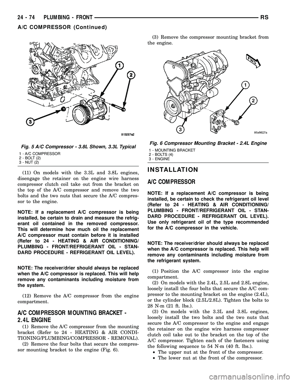
(11) On models with the 3.3L and 3.8L engines,
disengage the retainer on the engine wire harness
compressor clutch coil take out from the bracket on
the top of the A/C compressor and remove the two
bolts and the two nuts that secure the A/C compres-
sor to the engine.
NOTE: If a replacement A/C compressor is being
installed, be certain to drain and measure the refrig-
erant oil contained in the removed compressor.
This will determine how much oil the replacement
A/C compressor must contain before it is installed
(Refer to 24 - HEATING & AIR CONDITIONING/
PLUMBING - FRONT/REFRIGERANT OIL - STAN-
DARD PROCEDURE - REFRIGERANT OIL LEVEL).
NOTE: The receiver/drier should always be replaced
when the A/C compressor is replaced. This will help
remove any contaminants including moisture from
the system.
(12) Remove the A/C compressor from the engine
compartment.
A/C COMPRESSOR MOUNTING BRACKET -
2.4L ENGINE
(1) Remove the A/C compressor from the mounting
bracket (Refer to 24 - HEATING & AIR CONDI-
TIONING/PLUMBING/COMPRESSOR - REMOVAL).
(2) Remove the four bolts that secure the compres-
sor mounting bracket to the engine (Fig. 6).(3) Remove the compressor mounting bracket from
the engine.
INSTALLATION
A/C COMPRESSOR
NOTE: If a replacement A/C compressor is being
installed, be certain to check the refrigerant oil level
(Refer to 24 - HEATING & AIR CONDITIONING/
PLUMBING - FRONT/REFRIGERANT OIL - STAN-
DARD PROCEDURE - REFRIGERANT OIL LEVEL).
Use only refrigerant oil of the type recommended
for the A/C compressor in the vehicle.
NOTE: The receiver/drier should always be replaced
when the A/C compressor is replaced. This help will
remove any contaminants including moisture from
the refrigerant system.
(1) Position the A/C compressor into the engine
compartment.
(2) On models with the 2.4L, 2.5L and 2.8L engine,
loosely install the four bolts that secure the A/C com-
pressor to the mounting bracket on the engine (2.4L),
or the cylinder block (2.5L/2.8L). Tighten the bolts to
28 N´m (21 ft. lbs.).
(3) On models with the 3.3L and 3.8L engines,
loosely install the two bolts and the two nuts that
secure the A/C compressor to the engine and engage
the retainer on the engine wire harness compressor
clutch coil take out to the bracket on the top of the
A/C compressor. Tighten each of the fasteners using
the following sequence to 54 N´m (40 ft. lbs.).
²The upper nut at the front of the compressor.
²The lower nut at the front of the compressor.
Fig. 5 A/C Compressor - 3.8L Shown, 3.3L Typical
1 - A/C COMPRESSOR
2 - BOLT (2)
3 - NUT (2)
Fig. 6 Compressor Mounting Bracket - 2.4L Engine
1 - MOUNTING BRACKET
2 - BOLTS (4)
3 - ENGINE
24 - 74 PLUMBING - FRONTRS
A/C COMPRESSOR (Continued)
Page 2229 of 2339

(1) Position the A/C condenser into the engine
compartment.
(2) Carefully lower the A/C condenser straight
down to engage the lower mounting brackets to the
radiator.
(3) Engage the upper A/C condenser mounting
brackets to the radiator. Be sure that the upper
retaining clips are fully engaged to the upper mount-
ing brackets.
(4) Remove the tape or plugs from the opened
refrigerant line fittings and the condenser ports.
(5) Connect the A/C discharge line and the A/C liq-
uid line to the A/C condenser (Refer to 24 - HEAT-
ING & AIR CONDITIONING/PLUMBING/A/C
DISCHARGE LINE - INSTALLATION) and (Refer to
24 - HEATING & AIR CONDITIONING/PLUMBING/
A/C LIQUID LINE - INSTALLATION).
(6) Connect the transmission oil cooler lines to the
A/C Condenser. Be sure that the quick-connect fit-
tings are fully engaged to the cooler tapping block
(Refer to 7 - COOLING/TRANSMISSION - STAN-
DARD PROCEDURE - TRANSMISSION COOLING).
(7) Position the hood latch onto the front of the
radiator closure panel crossmember.
(8) Install the two screws that secure the hood
latch to the crossmember. Check and adjust the hoodlatch as required. Tighten the bolts to 14 N´m (123
in. lbs.).
(9) Position the radiator sight shield onto the radi-
ator closure panel crossmember.
(10) Install the five small screws that secure the
front fascia grille inserts to the radiator sight shield.
Tighten the screws to 2 N´m (17 in. lbs.).
(11) Install the two large screws that secure the
front fascia and the outboard ends of the radiator
sight shield to the radiator closure panel crossmem-
ber. Tighten the screws to 6 N´m (53 in. lbs.).
(12) Evacuate the refrigerant system (Refer to 24 -
HEATING & AIR CONDITIONING/PLUMBING -
FRONT/REFRIGERANT - STANDARD PROCE-
DURE - REFRIGERANT SYSTEM EVACUATE).
(13) Charge the refrigerant system (Refer to 24 -
HEATING & AIR CONDITIONING/PLUMBING -
FRONT/REFRIGERANT - STANDARD PROCE-
DURE - REFRIGERANT SYSTEM CHARGE).
2.5L/2.8L DIESEL ENGINES
NOTE: If the A/C condenser is being replaced, add
50 milliliters (1.7 fluid ounce) of refrigerant oil to the
refrigerant system. Use only refrigerant oil of the
type recommended for the A/C compressor in the
vehicle.
NOTE: Be certain that each of the radiator and con-
denser air seals are reinstalled in their proper loca-
tions. These air seals are required for proper A/C
and engine cooling system operation.
(1) Position the A/C condenser onto the right
mounting bracket and transmission oil cooler unit.
(2) Position the left mounting bracket onto the side
of the A/C condenser and transmission oil cooler.
(3) Install the screw that secures the left mounting
bracket to the side of the transmission oil cooler.
Tighten the screw to 5 N´m (45 in. lbs.).
(4) Install the two screws that secure each mount-
ing bracket to the sides of the A/C condenser. Tighten
the screws to 5 N´m (45 in. lbs.).
NOTE: Verify that the A/C condenser isolators are
all installed and positioned correctly.
(5) Position the A/C condenser, transmission oil
cooler, and mounting brackets into the vehicle as an
assembly. Be certain that the lower mounting brack-
ets are engaged into the rubber isolators located on
each side of the cooling module.
(6) Install the two screws that secure the top of
the mounting bracket on each side of the A/C con-
denser to the cooling module. Tighten the screws to 5
N´m (45 in. lbs.).
Fig. 11 A/C Condenser ± 2.5L/2.8L Diesel Engines
1 - BOLT (2)
2 - LOWER MOUNT ISOLATOR (2)
3 - A/C CONDENSER
24 - 78 PLUMBING - FRONTRS
A/C CONDENSER (Continued)
Page 2230 of 2339
(7) Remove the tape or plugs from the opened
refrigerant line fittings and the condenser ports.
(8) Connect the A/C discharge line and the A/C liq-
uid line to the A/C condenser (Refer to 24 - HEAT-
ING & AIR CONDITIONING/PLUMBING/A/C
DISCHARGE LINE - INSTALLATION) and (Refer to
24 - HEATING & AIR CONDITIONING/PLUMBING/
A/C LIQUID LINE - INSTALLATION).
(9) Reconnect the hoses to the transmission oil
cooler fittings on the left side of the cooling module
(Refer to 7 - COOLING/TRANSMISSION/TRANS
COOLER LINES - INSTALLATION).
(10) Reposition the hood latch to the front of the
radiator closure panel crossmember.
(11) Install the two screws that secure the hood
latch to the front of the radiator closure panel cross-
member. Check and adjust the hood latch as needed.
Tighten the screws to 14 N´m (123 in. lbs.).
(12) Position the radiator sight shield onto the
radiator closure panel crossmember.
(13) Install the five small screws that secure the
front fascia grille inserts to the radiator sight shield.
Tighten the screws to 2 N´m (17 in. lbs.).
(14) Install the two large screws that secure the
front fascia and the outboard ends of the radiator
sight shield to the radiator closure panel crossmem-
ber. Tighten the screws to 6 N´m (53 in. lbs.).
(15) Evacuate the refrigerant system (Refer to 24 -
HEATING & AIR CONDITIONING/PLUMBING -
FRONT/REFRIGERANT - STANDARD PROCE-
DURE - REFRIGERANT SYSTEM EVACUATE).
(16) Charge the refrigerant system (Refer to 24 -
HEATING & AIR CONDITIONING/PLUMBING -
FRONT/REFRIGERANT - STANDARD PROCE-
DURE - REFRIGERANT SYSTEM CHARGE).
A/C DISCHARGE LINE
REMOVAL
WARNING: REFER TO THE APPLICABLE WARN-
INGS AND CAUTIONS FOR THIS SYSTEM BEFORE
PERFORMING THE FOLLOWING OPERATION (Refer
to 24 - HEATING & AIR CONDITIONING/PLUMBING -
FRONT - WARNING - A/C PLUMBING) and (Refer to
24 - HEATING & AIR CONDITIONING/PLUMBING -
FRONT - CAUTION - A/C PLUMBING).
(1) Recover the refrigerant from the refrigerant
system (Refer to 24 - HEATING & AIR CONDITION-
ING/PLUMBING - FRONT/REFRIGERANT - STAN-
DARD PROCEDURE - REFRIGERANT SYSTEM
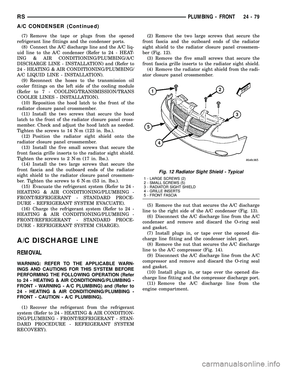
RECOVERY).(2) Remove the two large screws that secure the
front fascia and the outboard ends of the radiator
sight shield to the radiator closure panel crossmem-
ber (Fig. 12).
(3) Remove the five small screws that secure the
front fascia grille inserts to the radiator sight shield.
(4) Remove the radiator sight shield from the radi-
ator closure panel crossmember.
(5) Remove the nut that secures the A/C discharge
line to the right side of the A/C condenser (Fig. 13).
(6) Disconnect the A/C discharge line from the A/C
condenser and remove and discard the O-ring seal
and gasket.
(7) Install plugs in, or tape over the opened dis-
charge line fitting and the condenser inlet port.
(8) Remove the nut that secures the A/C discharge
line to the A/C compressor (Fig. 14).
(9) Disconnect the A/C discharge line from the A/C
compressor and remove and discard the O-ring seal
and gasket.
(10) Install plugs in, or tape over the opened dis-
charge line fitting and the compressor discharge port.
(11) Remove the A/C discharge line from the
engine compartment.
Fig. 12 Radiator Sight Shield - Typical
1 - LARGE SCREWS (2)
2 - SMALL SCREWS (5)
3 - RADIATOR SIGHT SHIELD
4 - GRILLE INSERTS
5 - FRONT FASCIA
RSPLUMBING - FRONT24-79
A/C CONDENSER (Continued)
Page 2245 of 2339
OPERATION
R-134a refrigerant is not compatible with R-12
refrigerant in an air conditioning system. Even a
small amount of R-12 added to an R-134a refrigerant
system will cause compressor failure, refrigerant oil
sludge or poor air conditioning system performance.
In addition, the PolyAlkylene Glycol (PAG) synthetic
refrigerant oils used in an R-134a refrigerant system
are not compatible with the mineral-based refriger-
ant oils used in an R-12 refrigerant system. R-134a
refrigerant system service ports, service tool couplers
and refrigerant dispensing bottles have all been
designed with unique fittings to ensure that an
R-134a system is not accidentally contaminated with
the wrong refrigerant (R-12). There are also labels
posted in the engine compartment of the vehicle and
on the compressor identifying to service technicians
that the air conditioning system is equipped with
R-134a.
REFRIGERANT OIL
DESCRIPTION
The refrigerant oil used in R-134a refrigerant sys-
tems is a synthetic-based, PolyAlkylene Glycol (PAG),
wax-free lubricant. Mineral-based R-12 refrigerant
oils are not compatible with PAG oils, and should
never be introduced to an R-134a refrigerant system.
There are different PAG oils available, and each con-
tains a different additive package. The compressor
used in this vehicle is designed to use an ND-8 PAG
refrigerant oil. Use only refrigerant oil of this same
type to service the refrigerant system.
OPERATION
After performing any refrigerant recovery or recy-
cling operation, always replenish the refrigerant sys-
tem with the same amount of the recommended
refrigerant oil as was removed. Too little refrigerant
oil can cause compressor damage, and too much can
reduce air conditioning system performance. PAG
refrigerant oil is much more hygroscopic than min-
eral oil, and will absorb any moisture it comes into
contact with, even moisture in the air. The PAG oil
container should always be kept tightly capped until
it is ready to be used. After use, recap the oil con-
tainer immediately to prevent moisture contamina-
tion.
STANDARD PROCEDURE
REFRIGERANT OIL LEVEL
WARNING: REFER TO THE APPLICABLE WARN-
INGS AND CAUTIONS FOR THIS SYSTEM BEFORE
PERFORMING THE FOLLOWING OPERATION (Refer
to 24 - HEATING & AIR CONDITIONING/PLUMBING -
FRONT - WARNING - A/C PLUMBING) and (Refer to
24 - HEATING & AIR CONDITIONING/PLUMBING -
FRONT - CAUTION - A/C PLUMBING).
CAUTION: Use only PAG oils that are designed to
work with R-134a refrigerant and the A/C compres-
sor in the vehicle. Refer to the underhood A/C Sys-
tem Specification Label.
It is important to have the correct amount of lubri-
cant in the A/C refrigerant system to ensure proper
lubrication of the A/C compressor. Too little lubricant
will result in damage to the compressor. Too much
lubricant will reduce the cooling capacity of the A/C
system and consequently result in higher discharge
air temperatures.
The lubricant used in the compressor is polyalka-
lene glycol PAG lubricant. Only the refrigerant lubri-
cant approved for use with this vehicle should be
used to service the system. Do not use any other
lubricant. The lubricant container should be kept
tightly capped until it is ready for use. Refrigerant
lubricant will quickly absorb any moisture it comes
in contact with.
It will not be necessary to check the oil level in the
A/C compressor or to add oil, unless there has been
an oil loss. An oil loss may occur due to a rupture or
leak from a refrigerant line, connector fitting, compo-
nent or component seal. If a leak occurs, add 30 mil-
liliters (1 fluid ounce) of the recommended
refrigerant oil to the refrigerant system after the
repair has been made. Refrigerant oil loss will be evi-
dent at the leak point by the presence of a wet, shiny
surface around the leak.
REFRIGERANT OIL LEVEL CHECK
When an air conditioning system is first assembled
at the factory, all components (except the A/C com-
pressor) are refrigerant oil free. After the refrigerant
system has been charged with (R-134a) refrigerant
and operated, the oil in the A/C compressor is dis-
persed through the lines and components. The A/C
evaporator, A/C condenser, and receiver/drier will
retain a significant amount of oil. Refer to the A/C
Component Refrigerant Oil Capacities table. When a
component is replaced, the specified amount of refrig-
erant oil must be added. When the compressor is
replaced, the amount of oil that is retained in the
24 - 94 PLUMBING - FRONTRS
REFRIGERANT (Continued)
Page 2254 of 2339
(7) Refill the engine cooling system (Refer to 7 -
COOLING - STANDARD PROCEDURE - COOLING
SYSTEM REFILL).
THERMAL CYCLING
If the rear heater core was emptied and was not
pre-filled, it will be necessary to thermal cycle the
vehicle at least two times to ensure that the rear
heater core is properly filled.
(1) Refill the engine cooling system (Refer to 7 -
COOLING - STANDARD PROCEDURE - COOLING
SYSTEM REFILL).
(2) Start the engine and allow it to operate until
the thermostat opens.
(3) Turn the engine off and allow it to cool.
(4) With the engine cold and not running, check
and top off the engine coolant level as necessary
(Refer to 7 - COOLING - STANDARD PROCEDURE
- COOLANT LEVEL CHECK) and (Refer to 7 -
COOLING - STANDARD PROCEDURE - COOLANT
- ADDING).
(5) Start the engine and allow it to operate until
the thermostat opens again.
(6) Turn the engine off and allow it to cool down
again.
(7) With the engine cold and not running, check
and top off the engine coolant level as necessary
(Refer to 7 - COOLING - STANDARD PROCEDURE
- COOLANT LEVEL CHECK) and (Refer to 7 -
COOLING - STANDARD PROCEDURE - COOLANT
- ADDING).
(8) Check the performance of the rear heater.
Refer to REAR HEATER PERFORMANCE CHECK.
REAR HEATER PERFORMANCE CHECK
Successful completion of the rear heater perfor-
mance check will confirm that the rear heater core is
properly filled with engine coolant. If the check is not
successful, either there is still air trapped in the rear
heater core or the rear heater plumbing is restricted.
This check should be performed with the vehicle in a
shop where the ambient temperature is about 21É C
(70É F).
(1) Start the engine and allow it to idle until it
warms up to normal operating temperature.
(2) Adjust the heater-A/C controls so that the front
heater is turned Off, the rear heater is set for full
Heat, and the rear blower motor is at its highest
speed setting.
(3) Use an accurate test thermometer to measure
the temperature of the air being discharged from the
rear heater outlet located at the base of the right
C-pillar.
(4) Proper discharge air temperature readings
should be from 57É to 63É C (135É to 145É F).REMOVAL
WARNING: REFER TO THE APPLICABLE WARN-
INGS AND CAUTIONS FOR THIS SYSTEM BEFORE
PERFORMING THE FOLLOWING OPERATION (Refer
to 24 - HEATING & AIR CONDITIONING/PLUMBING
FRONT - WARNING - HEATER PLUMBING).
(1) Drain the engine cooling system (Refer to 7 -
COOLING - STANDARD PROCEDURE - COOLING
SYSTEM DRAIN).
(2) Remove the right quarter trim panel and right
D-pillar trim panel from the quarter inner panel
(Refer to 23 - BODY/INTERIOR/QUARTER TRIM
PANEL - REMOVAL).
(3) Remove the rear heater distribution duct from
the right quarter inner panel (Refer to 24 - HEAT-
ING & AIR CONDITIONING/DISTRIBUTION -
REAR/REAR HEATER DISTRIBUTION DUCT -
REMOVAL).
(4) Remove the screw that secures the back of the
rear HVAC housing to the right D-pillar.
(5) Remove the screw that secures the front of the
rear HVAC housing to the right quarter inner panel.
(6) Take the proper precautions to protect the car-
peting below the rear heater core from spilled engine
coolant and have absorbent toweling readily avail-
able to mop up any spills.
(7) Disconnect the heater hoses at the rear heater
core (Refer to 24 - HEATING & AIR CONDITION-
ING/PLUMBING - REAR/HEATER HOSE -
REMOVAL).
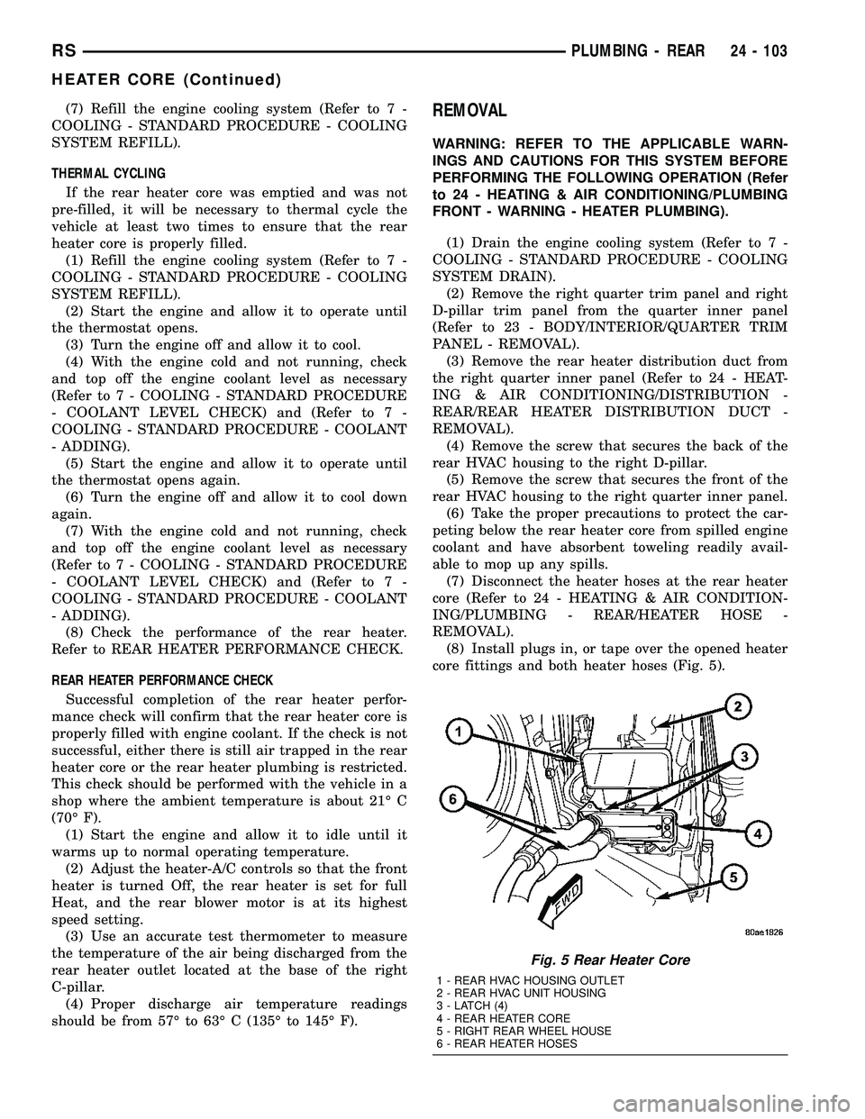
(8) Install plugs in, or tape over the opened heater
core fittings and both heater hoses (Fig. 5).
Fig. 5 Rear Heater Core
1 - REAR HVAC HOUSING OUTLET
2 - REAR HVAC UNIT HOUSING
3 - LATCH (4)
4 - REAR HEATER CORE
5 - RIGHT REAR WHEEL HOUSE
6 - REAR HEATER HOSES
RSPLUMBING - REAR24 - 103
HEATER CORE (Continued)
Page 2265 of 2339
The supplemental cabin heater only operates when
the engine is running, the mileage exceeds 8 kilome-
ter (5 mph) and the fuel tank volume exceeds 1/8 of a
tank. The supplemental heater control module moni-
tors blower speed and combustion during its start-up.
The cabin heater should operate if the coolant tem-
perature is below 40É C (104É F).
AUTOMATIC TEMPERATURE CONTROL
SYSTEM
The automatic temperature control (ATC) system
will activate the supplemental cabin heater based on
engine coolant temperature and interior component
settings. The cabin heater can operate in a full or
partial load range as well as an idle mode all depen-
dent on the engine coolant temperature. The cabin
heater will also turn off if the A/C-heater tempera-
ture control is lowered to less than the lower set
point. The cabin heater can take up to three minutes
to completely shut down when either the heater tem-
perature is set below the lower set point or the vehi-
cle ignition is shut down.
NOTE: Do not apply a strong vacuum source such
as a garage ventilation system directly on the sup-
plemental cabin heater exhaust line. Too strong of a
vacuum can prevent the supplemental cabin heater
from starting. If required, place the vacuum source
at least 75 mm (3 in.) away from the exhaust line.
The supplemental cabin heater only operates when
the engine is running, the mileage exceeds 8 kilome-ter (5 mph) and the fuel tank volume exceeds 1/8 of a
tank. The supplemental heater control module moni-
tors blower speed and combustion during its start-up.
The cabin heater should operate if the coolant tem-
perature is below 40É C (104É F).
WARNING
WARNING: DO NOT OPERATE THE DIESEL SUP-
PLEMENTAL CABIN HEATER IN AN ENCLOSED
AREA SUCH AS A GARAGE THAT DOES NOT HAVE
EXHAUST VENTILATION FACILITIES. ALWAYS VENT
THE CABIN HEATER EXHAUST WHEN OPERATING
THE CABIN HEATER. ALLOW THE DIESEL SUPPLE-
MENTAL CABIN HEATER TO COOL BEFORE PER-
FORMING ANY SERVICE PROCEDURES TO THE
CABIN HEATER. VERIFY THAT ALL DIESEL SUP-
PLEMENTAL CABIN HEATER FUEL LINES ARE
SECURELY FASTENED TO THEIR RESPECTIVE
COMPONENTS BEFORE PERFORMING ANY SER-
VICE PROCEDURES TO THE CABIN HEATER. FAIL-
URE TO FOLLOW THESE INSTRUCTION MAY
RESULT IN PERSONAL INJURY OR DEATH.
DIAGNOSIS AND TESTING
SUPPLEMENTAL CABIN HEATER
Refer to the Symptoms Diagnosis table for basic
checks of the diesel fueled supplemental cabin heater.
SYMPTOMS DIAGNOSIS
Symptom Possible Causes
Smell of diesel fuel. Check cabin heater system integration in vehicle's fuel system. Check
fuel lines for leakage, kinks or obstructions. If OK, Inspect the inlet
muffler, drain as necessary. Re-test the cabin heater and re-inspect.
Inspect the exhaust tube and cabin heater for the presence of external
fuel. If presence of external fuel is observed on the heater unit or in the
exhaust tube or after draining and testing. Remove the cabin heater
from vehicle and repair or replace components as required.
Heater does not achieve full load
operation.Check cabin heater operation with DRBIIITscan tool and replace
components as required.
Continuous white smoke from heater
exhaust during combustion operation.Check cabin heater operation with DRBIIITscan tool and replace
components as required. White smoke is typical in extreme weather
conditions.
Heater can not be switched off. Check cabin heater operation with DRBIIITscan tool and replace
components as required.
Heater does not operate. Diagnosis cabin heater control module using the DRBIIITscan tool and
the procedures listed in Vehicle Performance under Cabin Heater
Diagnosis in Group 18.
24 - 114 CABIN HEATERRS
CABIN HEATER (Continued)
Page 2266 of 2339
Symptom Possible Causes
Loss of coolant (Leakage) or heater
develops smoke during combustion
operation and exhaust has an
extremely sweet smell.Inspect coolant hoses for leakage, kinks or loose hose connection.
Inspect the exhaust tube assembly for continuous flow, if OK there is an
internal heater leak and cabin heater should be inspected and
components should be replaced as required.
Loss of fuel (dripping). Check cabin heater system integration in vehicles fuel system. Check
fuel line connection for leakage. If OK there is an internal leak and
cabin heater should be inspected and replaced as required.
AIR INTAKE PIPE
REMOVAL
NOTE: The air intake tube for the supplemental
cabin heater is part of an assembly that includes
the heater cooling intake and return pipes. If the
cabin heater air intake tube requires removal or
replacement the entire cabin heater assembly will
require removal or replacement.
(1) Drain the engine cooling system (Refer to 7 -
COOLING - STANDARD PROCEDURE).
(2) Remove clamps from the cabin heater tubes at
the lower heater port and the lower EGR connector
which are located under the hood.
(3) Remove the retaining clamp at the cabin
heater air intake muffler connection (Refer to 24 -
HEATING & AIR CONDITIONING/CABIN HEAT-
ER/INLET MUFFLER - REMOVAL).
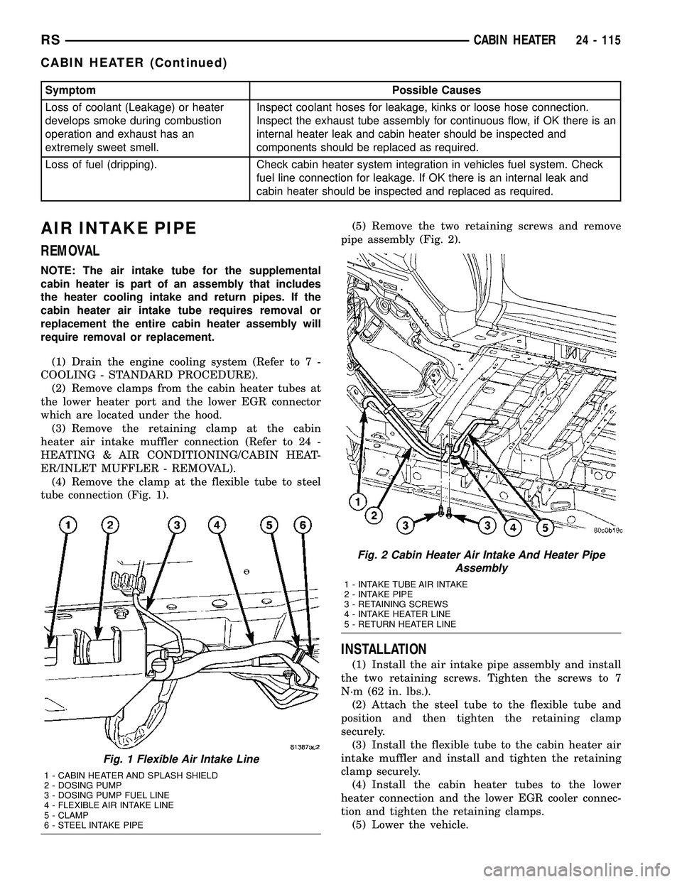
(4) Remove the clamp at the flexible tube to steel
tube connection (Fig. 1).(5) Remove the two retaining screws and remove
pipe assembly (Fig. 2).
INSTALLATION
(1) Install the air intake pipe assembly and install
the two retaining screws. Tighten the screws to 7
N´m (62 in. lbs.).
(2) Attach the steel tube to the flexible tube and
position and then tighten the retaining clamp
securely.
(3) Install the flexible tube to the cabin heater air
intake muffler and install and tighten the retaining
clamp securely.
(4) Install the cabin heater tubes to the lower
heater connection and the lower EGR cooler connec-
tion and tighten the retaining clamps.
(5) Lower the vehicle.
Fig. 1 Flexible Air Intake Line
1 - CABIN HEATER AND SPLASH SHIELD
2 - DOSING PUMP
3 - DOSING PUMP FUEL LINE
4 - FLEXIBLE AIR INTAKE LINE
5 - CLAMP
6 - STEEL INTAKE PIPE
Fig. 2 Cabin Heater Air Intake And Heater Pipe
Assembly
1 - INTAKE TUBE AIR INTAKE
2 - INTAKE PIPE
3 - RETAINING SCREWS
4 - INTAKE HEATER LINE
5 - RETURN HEATER LINE
RSCABIN HEATER24 - 115
CABIN HEATER (Continued)