2005 CHRYSLER CARAVAN check engine
[x] Cancel search: check enginePage 1742 of 2339
TRANSMISSION CONTROL
RELAY
DESCRIPTION
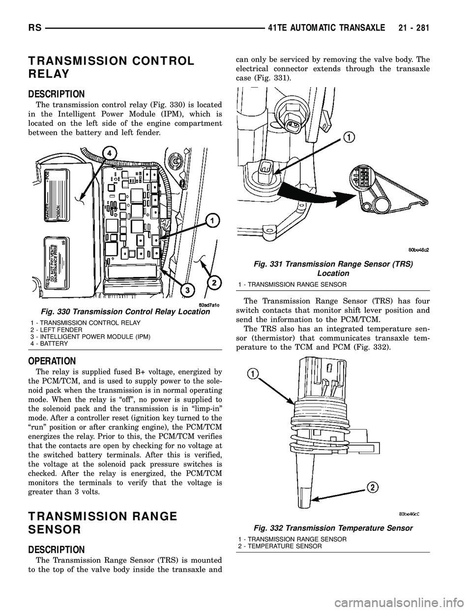
The transmission control relay (Fig. 330) is located
in the Intelligent Power Module (IPM), which is
located on the left side of the engine compartment
between the battery and left fender.
OPERATION
The relay is supplied fused B+ voltage, energized by
the PCM/TCM, and is used to supply power to the sole-
noid pack when the transmission is in normal operating
mode. When the relay is ªoffº, no power is supplied to
the solenoid pack and the transmission is in ªlimp-inº
mode. After a controller reset (ignition key turned to the
ªrunº position or after cranking engine), the PCM/TCM
energizes the relay. Prior to this, the PCM/TCM verifies
that the contacts are open by checking for no voltage at
the switched battery terminals. After this is verified,
the voltage at the solenoid pack pressure switches is
checked. After the relay is energized, the PCM/TCM
monitors the terminals to verify that the voltage is
greater than 3 volts.
TRANSMISSION RANGE
SENSOR
DESCRIPTION
The Transmission Range Sensor (TRS) is mounted
to the top of the valve body inside the transaxle andcan only be serviced by removing the valve body. The
electrical connector extends through the transaxle
case (Fig. 331).
The Transmission Range Sensor (TRS) has four
switch contacts that monitor shift lever position and
send the information to the PCM/TCM.
The TRS also has an integrated temperature sen-
sor (thermistor) that communicates transaxle tem-
perature to the TCM and PCM (Fig. 332).
Fig. 330 Transmission Control Relay Location
1 - TRANSMISSION CONTROL RELAY
2 - LEFT FENDER
3 - INTELLIGENT POWER MODULE (IPM)
4 - BATTERY
Fig. 331 Transmission Range Sensor (TRS)
Location
1 - TRANSMISSION RANGE SENSOR
Fig. 332 Transmission Temperature Sensor
1 - TRANSMISSION RANGE SENSOR
2 - TEMPERATURE SENSOR
RS41TE AUTOMATIC TRANSAXLE21 - 281
Page 1791 of 2339
DESCRIPTION N´m Ft. Lbs. In. Lbs.
Sliding door glass nuts 3.4 Ð 30
Sliding door latch striker 28 21 Ð
Sliding door to roller arm bracket 12 9 Ð
Storage bin track guide to seat riser 3.5 Ð 31
Sunroof opening panel to lifter arm screws 5 44
Sunroof opening panel motor screws 4 35
Sunroof trough bracket to roof bolts 6 53
Sunroof trough to trough bracket bolts 6 53
Sunroof trough bracket bolts 6 53
Support cylinders to liftgate 28 21 Ð
BODY LUBRICATION
LUBRICATION REQUIREMENTS
Body mechanisms and linkages should be
inspected, cleaned, and lubricated, as required, to
maintain ease of operation and to provide protection
against rust and wear. When performing other under
hood services, the hood latch release mechanism and
safety catch should be inspected, cleaned, and lubri-
cated. During the winter season, external door lock
cylinders should be lubricated to assure proper oper-
ation when exposed to water and ice.
Prior to the application of any lubricant, the parts
concerned should be wiped clean to remove dust and
grit. If necessary, a suitable solvent can be used to
clean the item to be lubricated. After lubricating a
component, any excess oil or grease should be
removed.
LUBRICANT APPLICATION
DOOR LOCK CYLINDERS
(1) Apply a small amount of lubricant directly into
the lock cylinder.
(2) Apply a small amount of lubricant to the key.
(3) Insert key into lock cylinder and cycle the
mechanism from the locked to the unlocked position.
NOTE: Do not add more lubricant.
(4) Cycle the lock cylinder mechanism several
times to allow the lubricant to flow throughout the
cylinder.
(5) Wipe all lubricant from exterior of lock cylinder
and key.ALL OTHER BODY MECHANISMS
(1) Clean component as described above.
(2) Apply specified lubricant to all pivoting and
sliding contact areas of component.
LUBRICANT USAGE
ENGINE OIL
²Door Hinges ± Hinge Pin and Pivot Contact
Areas
²Hood Hinges ± Pivot Points
²Liftgate Hinges
MOPARTSPRAY WHITE LUBE OR EQUIVALENT
²Door Check Straps
²Liftgate Latches
²Liftgate Prop Pivots
²Ash Receiver
²Fuel Filler Door Remote Control Latch Mecha-
nism
²Parking Brake Mechanism
²Sliding Seat Tracks
²Liftgate Latch
MOPARTMultipurpose GREASE OR EQUIVALENT
²All Other Hood Mechanisms
MOPARTLOCK CYLINDER LUBRICANT OR
EQUIVALENT
²Door Lock Cylinders
²Liftgate Lock Cylinder
23 - 12 BODYRS
BODY (Continued)
Page 1831 of 2339
(6) Remove outboard cowl grille/fender bracket
screw and antenna right side only.
(7) Remove fender bolt to lower rocker panel.
(8) Remove fender bolt to lower cowl.
(9) Support/remove hood.
(10) Pull fascia away from fender.
(11) Remove bolts attaching fender to upper rail.
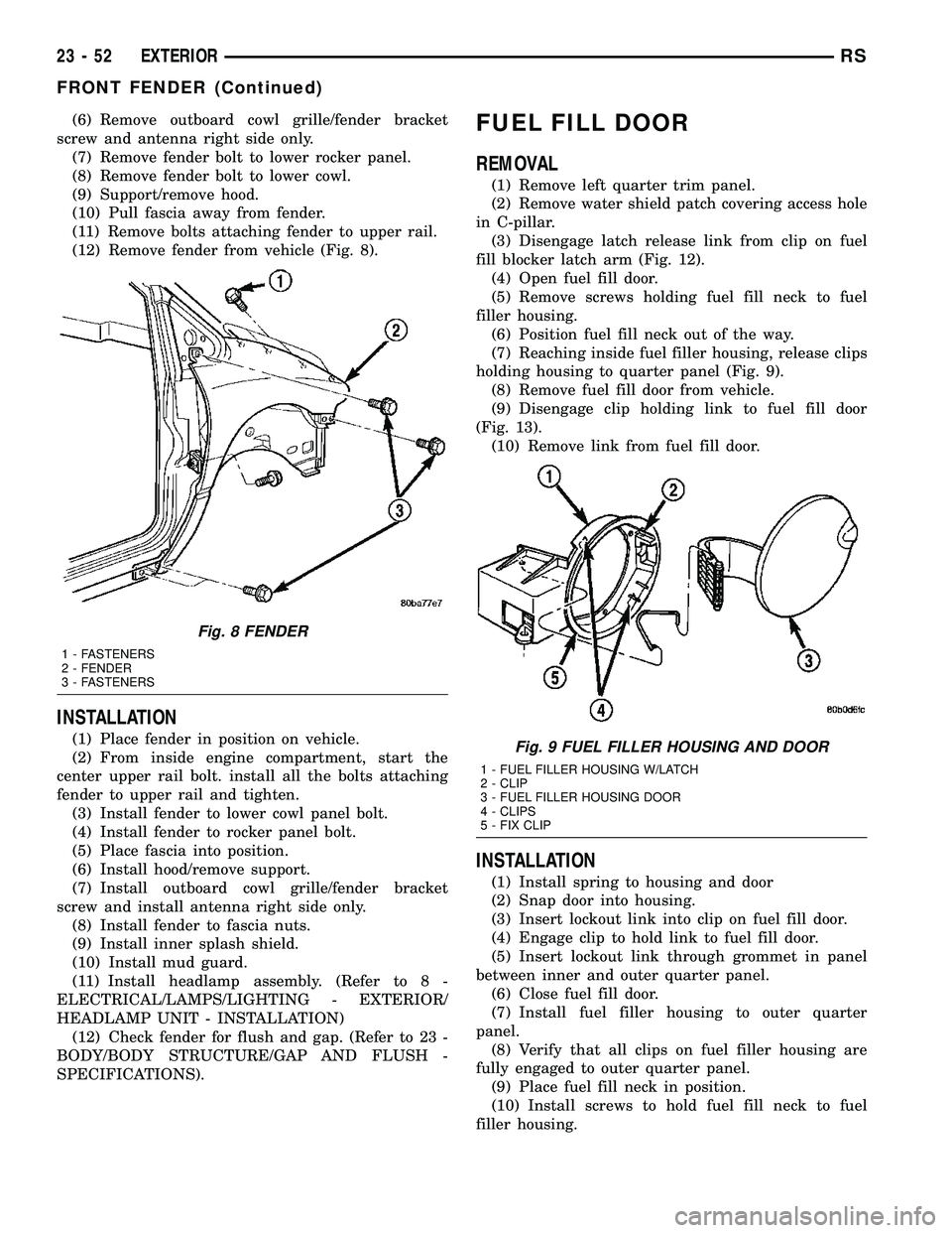
(12) Remove fender from vehicle (Fig. 8).
INSTALLATION
(1) Place fender in position on vehicle.
(2) From inside engine compartment, start the
center upper rail bolt. install all the bolts attaching
fender to upper rail and tighten.
(3) Install fender to lower cowl panel bolt.
(4) Install fender to rocker panel bolt.
(5) Place fascia into position.
(6) Install hood/remove support.
(7) Install outboard cowl grille/fender bracket
screw and install antenna right side only.
(8) Install fender to fascia nuts.
(9) Install inner splash shield.
(10) Install mud guard.
(11) Install headlamp assembly. (Refer to 8 -
ELECTRICAL/LAMPS/LIGHTING - EXTERIOR/
HEADLAMP UNIT - INSTALLATION)
(12) Check fender for flush and gap. (Refer to 23 -
BODY/BODY STRUCTURE/GAP AND FLUSH -
SPECIFICATIONS).
FUEL FILL DOOR
REMOVAL
(1) Remove left quarter trim panel.
(2) Remove water shield patch covering access hole
in C-pillar.
(3) Disengage latch release link from clip on fuel
fill blocker latch arm (Fig. 12).
(4) Open fuel fill door.
(5) Remove screws holding fuel fill neck to fuel
filler housing.
(6) Position fuel fill neck out of the way.
(7) Reaching inside fuel filler housing, release clips
holding housing to quarter panel (Fig. 9).
(8) Remove fuel fill door from vehicle.
(9) Disengage clip holding link to fuel fill door
(Fig. 13).
(10) Remove link from fuel fill door.
INSTALLATION
(1) Install spring to housing and door
(2) Snap door into housing.
(3) Insert lockout link into clip on fuel fill door.
(4) Engage clip to hold link to fuel fill door.
(5) Insert lockout link through grommet in panel
between inner and outer quarter panel.
(6) Close fuel fill door.
(7) Install fuel filler housing to outer quarter
panel.
(8) Verify that all clips on fuel filler housing are
fully engaged to outer quarter panel.
(9) Place fuel fill neck in position.
(10) Install screws to hold fuel fill neck to fuel
filler housing.
Fig. 8 FENDER
1 - FASTENERS
2 - FENDER
3 - FASTENERS
Fig. 9 FUEL FILLER HOUSING AND DOOR
1 - FUEL FILLER HOUSING W/LATCH
2 - CLIP
3 - FUEL FILLER HOUSING DOOR
4 - CLIPS
5 - FIX CLIP
23 - 52 EXTERIORRS
FRONT FENDER (Continued)
Page 2160 of 2339
Condition Possible Causes Correction
Normal pressures, but A/C
Performance Test air
temperatures at center panel
outlet are too high.1. Excessive refrigerant oil in
system.1. See Refrigerant Oil Level in this group.
Recover the refrigerant from the refrigerant
system and inspect the refrigerant oil content.
Restore the refrigerant oil to the proper level, if
required.
2. Blend door actuator
improperly installed or faulty.2. See Blend Door Actuator in this group. Inspect
the actuator for proper operation and replace, if
required.
3. Blend door inoperative or
sealing improperly.3. See HVAC Housing in this group. Inspect the
blend door for proper operation and sealing.
Repair if required.
4. Blend door not in full cold
position.Use a DRBIII Scan Tool to check for DTCs and
blend door position. Refer to Body Diagnostic
Procedures.
The low side pressure is
normal or slightly low, and the
high side pressure is too low.1. Low refrigerant system
charge.1. See Refrigerant System Leaks in this group.
Test the refrigerant system for leaks. Repair,
evacuate and charge the refrigerant system, if
required.
2. Refrigerant flow through
the A/C evaporator is
restricted.2. See A/C Evaporator in this group. Replace the
restricted A/C evaporator, if required.
3. Faulty A/C compressor. 3. See A/C Compressor in this group. Replace
the compressor, if required.
The low side pressure is
normal or slightly high, and
the high side pressure is too
high.1. A/C condenser air flow
restricted.1. Check the A/C condenser for damaged fins,
foreign objects obstructing air flow through the
condenser fins, and missing or improperly
installed air seals. Clean, repair, or replace
components as required.
2. Refrigerant flow through
the receiver/drier is
restricted.2. See Receiver/Drier in this group. Replace the
restricted receiver/drier, if required.
3. Inoperative radiator
cooling fan.3. Test the radiator cooling fan and replace, if
required. Refer to Group 7.
4. Refrigerant system
overcharged.4. See Refrigerant System Charge in this group.
Recover the refrigerant from the refrigerant
system. Charge the refrigerant system to the
proper level, if required.
5. Air in the refrigerant
system.5. See Refrigerant System Leaks in this group.
Test the refrigerant system for leaks. Repair,
evacuate and charge the refrigerant system, if
required.
6. Engine overheating. 6. Test the engine cooling system and repair, if
required. Refer to Group 7.
The low side pressure is too
high, and the high side
pressure is too low.1. Accessory drive belt
slipping.1. Inspect the accessory drive belt condition and
tension. Tighten or replace the accessory drive
belt, if required. Refer to Group 7.
2. Faulty A/C expansion
valve.2. See A/C Expansion Valve in this group.
Replace the valve, if required.
3. Faulty A/C compressor. 3. See A/C Compressor in this group. Replace
the compressor, if required.
RSHEATING & AIR CONDITIONING24-9
HEATING & AIR CONDITIONING (Continued)
Page 2161 of 2339
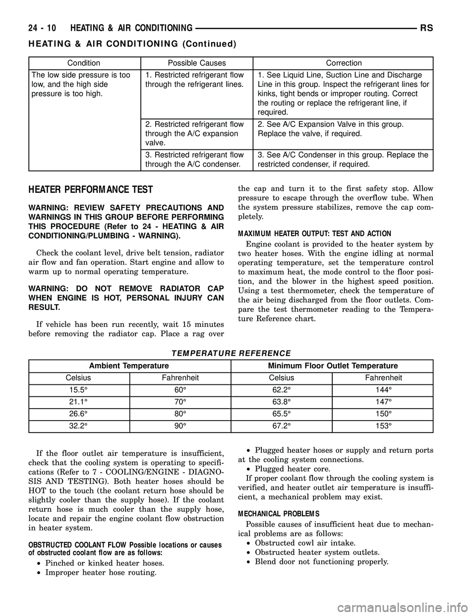
Condition Possible Causes Correction
The low side pressure is too
low, and the high side
pressure is too high.1. Restricted refrigerant flow
through the refrigerant lines.1. See Liquid Line, Suction Line and Discharge
Line in this group. Inspect the refrigerant lines for
kinks, tight bends or improper routing. Correct
the routing or replace the refrigerant line, if
required.
2. Restricted refrigerant flow
through the A/C expansion
valve.2. See A/C Expansion Valve in this group.
Replace the valve, if required.
3. Restricted refrigerant flow
through the A/C condenser.3. See A/C Condenser in this group. Replace the
restricted condenser, if required.
HEATER PERFORMANCE TEST
WARNING: REVIEW SAFETY PRECAUTIONS AND
WARNINGS IN THIS GROUP BEFORE PERFORMING
THIS PROCEDURE (Refer to 24 - HEATING & AIR
CONDITIONING/PLUMBING - WARNING).
Check the coolant level, drive belt tension, radiator
air flow and fan operation. Start engine and allow to
warm up to normal operating temperature.
WARNING: DO NOT REMOVE RADIATOR CAP
WHEN ENGINE IS HOT, PERSONAL INJURY CAN
RESULT.
If vehicle has been run recently, wait 15 minutes
before removing the radiator cap. Place a rag overthe cap and turn it to the first safety stop. Allow
pressure to escape through the overflow tube. When
the system pressure stabilizes, remove the cap com-
pletely.
MAXIMUM HEATER OUTPUT: TEST AND ACTION
Engine coolant is provided to the heater system by
two heater hoses. With the engine idling at normal
operating temperature, set the temperature control
to maximum heat, the mode control to the floor posi-
tion, and the blower in the highest speed position.
Using a test thermometer, check the temperature of
the air being discharged from the floor outlets. Com-
pare the test thermometer reading to the Tempera-
ture Reference chart.
TEMPERATURE REFERENCE
Ambient Temperature Minimum Floor Outlet Temperature
Celsius Fahrenheit Celsius Fahrenheit
15.5É 60É 62.2É 144É
21.1É 70É 63.8É 147É
26.6É 80É 65.5É 150É
32.2É 90É 67.2É 153É
If the floor outlet air temperature is insufficient,
check that the cooling system is operating to specifi-
cations (Refer to 7 - COOLING/ENGINE - DIAGNO-
SIS AND TESTING). Both heater hoses should be
HOT to the touch (the coolant return hose should be
slightly cooler than the supply hose). If the coolant
return hose is much cooler than the supply hose,
locate and repair the engine coolant flow obstruction
in heater system.
OBSTRUCTED COOLANT FLOW Possible locations or causes
of obstructed coolant flow are as follows:
²Pinched or kinked heater hoses.
²Improper heater hose routing.²Plugged heater hoses or supply and return ports
at the cooling system connections.
²Plugged heater core.
If proper coolant flow through the cooling system is
verified, and heater outlet air temperature is insuffi-
cient, a mechanical problem may exist.
MECHANICAL PROBLEMS
Possible causes of insufficient heat due to mechan-
ical problems are as follows:
²Obstructed cowl air intake.
²Obstructed heater system outlets.
²Blend door not functioning properly.
24 - 10 HEATING & AIR CONDITIONINGRS
HEATING & AIR CONDITIONING (Continued)
Page 2165 of 2339
clutch plate into contact with the clutch pulley and
drives the compressor shaft. When the coil is not
energized, the pulley freewheels on the clutch hub
bearing, which is part of the pulley.
A zener diode is connected in parallel with the
clutch electromagnetic coil. This diode controls the
dissipation of voltage induced into the coil windings
by the collapsing of the electromagnetic fields that
occurs when the compressor clutch is disengaged.
The zener diode dissipates this induced voltage by
regulating a current path to ground. This arrange-
ment serves to protect other circuits and components
from potentially damaging voltage spikes in the vehi-
cle electrical system that might occur if the voltage
induced in the clutch coil windings could not be dis-
sipated.
The compressor clutch engagement is controlled by
several components: the heater-A/C controls in the
passenger compartment, the A/C pressure transducer
on the liquid line, the evaporator temperature sensor
on the expansion valve for automatic temperature
control (ATC) system or on the HVAC housing for
manual temperature control (MTC) system, the Pow-
ertrain Control Module (PCM) in the engine compart-
ment, and the compressor clutch relay in the
Integrated Power Module (IPM). The PCM may delay
compressor clutch engagement for up to thirty sec-
onds (Refer to 8 - ELECTRICAL/ELECTRONIC
CONTROL MODULES/POWERTRAIN CONTROL
MODULE - DESCRIPTION - PCM OPERATION).
DIAGNOSIS AND TESTING
A/C COMPRESSOR CLUTCH COIL
The air conditioning compressor clutch coil electri-
cal circuit is controlled by the powertrain control
module (PCM) through the A/C compressor clutch
relay, which is located in the integrated power mod-
ule (IPM) in the engine compartment. Begin testing
of a suspected compressor clutch coil problem by per-
forming the preliminary checks.
PRELIMINARY CHECKS
(1) If the compressor clutch will not engage, verify
the refrigerant charge level (Refer to 24 - HEATING
& AIR CONDITIONING/PLUMBING - FRONT/RE-
FRIGERANT - DIAGNOSIS AND TESTING -
REFRIGERANT CHARGE LEVEL). If the refriger-
ant charge level is OK, go to Step 2. If the refriger-
ant charge level is not OK, adjust the refrigerant
charge as required.
(2) If the A/C compressor clutch still will not
engage, disconnect the wire harness connector for the
A/C pressure transducer and check for battery cur-
rent at the connector with the engine running and
the A/C-heater control set to the A/C mode. If OK, go
to TESTS. If not OK, refer to Body Diagnostic Proce-
dures to perform further diagnosis.
TESTS
(1) Verify the battery state of charge (Refer to 8 -
ELECTRICAL/BATTERY SYSTEM/BATTERY -
DIAGNOSIS AND TESTING).
(2) Connect an ammeter (0 to 10 ampere scale
selected) in series with the clutch coil feed terminal.
Connect a voltmeter (0 to 20 volt scale selected) to
measure voltage across the battery and the clutch
coil.
(3) With the heater-A/C control in the A/C mode
and the blower at low speed, start the engine and
allow it to run at a normal idle speed.
(4) The compressor clutch should engage immedi-
ately, and the clutch coil voltage should be within
two volts of the battery voltage. If the coil voltage is
not within two volts of battery voltage, test the
clutch coil feed circuit for excessive voltage drop. If
the compressor clutch does not engage, refer to Body
Diagnostic Procedures to perform further diagnosis.
(5) For the acceptable A/C clutch coil current draw
specificationsrefer to 24 - HEATING & AIR CONDI-
TIONING - SPECIFICATIONS. Specifications apply
for a work area temperature of 21É C (70É F). If volt-
age is more than 12.5 volts, add electrical loads by
turning on electrical accessories until voltage reads
below 12.5 volts.
(a) If the compressor clutch coil current reading
is zero, the coil is open and must be replaced.
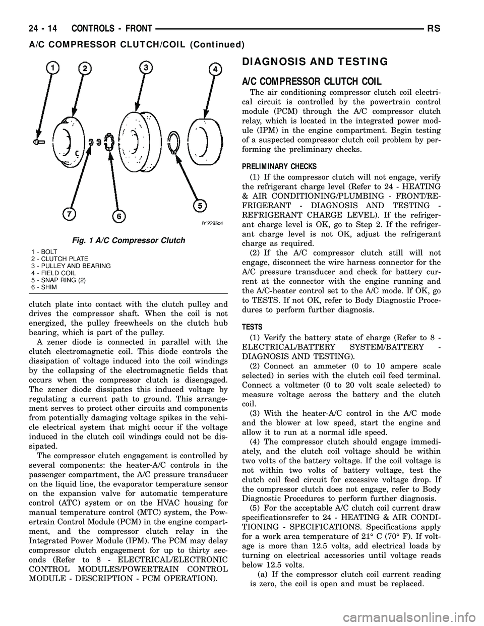
Fig. 1 A/C Compressor Clutch
1 - BOLT
2 - CLUTCH PLATE
3 - PULLEY AND BEARING
4 - FIELD COIL
5 - SNAP RING (2)
6 - SHIM
24 - 14 CONTROLS - FRONTRS
A/C COMPRESSOR CLUTCH/COIL (Continued)
Page 2166 of 2339
(b) If the compressor clutch coil current reading
is four amperes or more, the coil is shorted and
must be replaced.
STANDARD PROCEDURE
CLUTCH INSPECTION
NOTE: The compressor clutch can be serviced in
the vehicle. The refrigerant system can remain fully-
charged during compressor clutch, pulley, or coil
replacement.
Examine the friction surfaces of the clutch pulley
and the clutch plate for wear. The pulley and plate
should be replaced if there is excessive wear or scor-
ing.
If the friction surfaces are oily, inspect the shaft
and nose area of the A/C compressor for refrigerant
oil. If refrigerant oil is found, the compressor shaft
seal is leaking and the A/C compressor must be
replaced.
Check the clutch pulley bearing for roughness or
excessive leakage of grease. Replace the pulley and
bearing assembly, if required.
A/C CLUTCH BREAK-IN
After a new A/C compressor clutch has been
installed, cycle the compressor clutch approximately
twenty times (five seconds on, then five seconds off).
During this procedure, set the A/C-heater controls to
the A/C Recirculation Mode, the blower motor in the
highest speed position, and the engine speed at 1500
to 2000 rpm. This procedure (burnishing) will seat
the opposing friction surfaces of the compressor
clutch, which provides optimum compressor clutch
torque capability.
REMOVAL
NOTE: The compressor clutch can be serviced in
the vehicle. The refrigerant system can remain fully-
charged during compressor clutch, pulley, or coil
replacement.
(1) Disconnect and isolate the negative battery
cable.
(2) Remove the accessory drive belt (Refer to 7 -
COOLING/ACCESSORY DRIVE/DRIVE BELTS -
REMOVAL).
(3) Raise and support the vehicle.
(4) Disconnect the engine wire harness connector
for the compressor clutch coil from the clutch coil pig-
tail wire connector on the top of the A/C compressor.
(5) On models with the 3.3L and 3.8L engines, dis-
engage the retainer on the engine wire harness com-pressor clutch coil take out from the bracket on the
top of the A/C compressor.
(6) On models with the 2.4L, 2.5L and 2.8L
engines, remove all of the compressor mounting bolts
except the upper left (rear of the A/C compressor),
which should only be loosened. Allow the front (pul-
ley end) of the A/C compressor to tilt downward far
enough to access the clutch for removal, then tighten
the loosened upper left compressor mounting bolt.
(7) On models with the 3.3L and 3.8L engines,
remove the two bolts and two nuts that secure the
A/C compressor to the engine. Disengage the mount-
ing ear at the front of the A/C compressor from the
stud on the engine, allow the front (pulley end) of the
A/C compressor to tilt downward far enough to access
the clutch for removal, then reinstall and tighten the
upper left compressor mounting bolt.
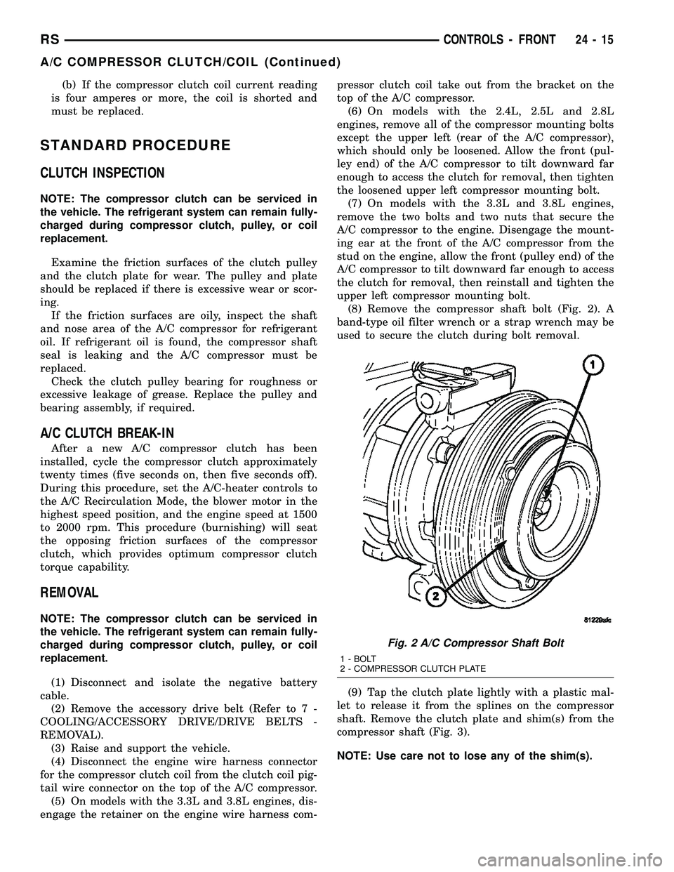
(8) Remove the compressor shaft bolt (Fig. 2). A
band-type oil filter wrench or a strap wrench may be
used to secure the clutch during bolt removal.
(9) Tap the clutch plate lightly with a plastic mal-
let to release it from the splines on the compressor
shaft. Remove the clutch plate and shim(s) from the
compressor shaft (Fig. 3).
NOTE: Use care not to lose any of the shim(s).
Fig. 2 A/C Compressor Shaft Bolt
1 - BOLT
2 - COMPRESSOR CLUTCH PLATE
RSCONTROLS - FRONT24-15
A/C COMPRESSOR CLUTCH/COIL (Continued)
Page 2168 of 2339
compressor. The bevel side of the snap ring must face
outward and both snap ring eyelets must be oriented
to the right or the left of the clutch coil dowel pin
location on the A/C compressor. Be certain that the
snap ring is fully and properly seated in the groove.
CAUTION: If the snap ring is not fully seated in the
groove it will vibrate out, resulting in a clutch fail-
ure and severe damage to the compressor front
cover.
(3) Install and securely tighten the screw that
secures the clutch coil pigtail wire connector bracket
and ground clip to the top of the compressor housing.
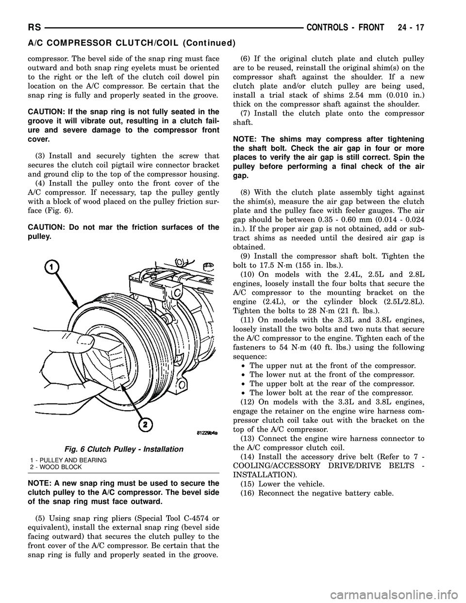
(4) Install the pulley onto the front cover of the
A/C compressor. If necessary, tap the pulley gently
with a block of wood placed on the pulley friction sur-
face (Fig. 6).
CAUTION: Do not mar the friction surfaces of the
pulley.
NOTE: A new snap ring must be used to secure the
clutch pulley to the A/C compressor. The bevel side
of the snap ring must face outward.
(5) Using snap ring pliers (Special Tool C-4574 or
equivalent), install the external snap ring (bevel side
facing outward) that secures the clutch pulley to the
front cover of the A/C compressor. Be certain that the
snap ring is fully and properly seated in the groove.(6) If the original clutch plate and clutch pulley
are to be reused, reinstall the original shim(s) on the
compressor shaft against the shoulder. If a new
clutch plate and/or clutch pulley are being used,
install a trial stack of shims 2.54 mm (0.010 in.)
thick on the compressor shaft against the shoulder.
(7) Install the clutch plate onto the compressor
shaft.
NOTE: The shims may compress after tightening
the shaft bolt. Check the air gap in four or more
places to verify the air gap is still correct. Spin the
pulley before performing a final check of the air
gap.
(8) With the clutch plate assembly tight against
the shim(s), measure the air gap between the clutch
plate and the pulley face with feeler gauges. The air
gap should be between 0.35 - 0.60 mm (0.014 - 0.024
in.). If the proper air gap is not obtained, add or sub-
tract shims as needed until the desired air gap is
obtained.
(9) Install the compressor shaft bolt. Tighten the
bolt to 17.5 N´m (155 in. lbs.).
(10) On models with the 2.4L, 2.5L and 2.8L
engines, loosely install the four bolts that secure the
A/C compressor to the mounting bracket on the
engine (2.4L), or the cylinder block (2.5L/2.8L).
Tighten the bolts to 28 N´m (21 ft. lbs.).
(11) On models with the 3.3L and 3.8L engines,
loosely install the two bolts and two nuts that secure
the A/C compressor to the engine. Tighten each of the
fasteners to 54 N´m (40 ft. lbs.) using the following
sequence:
²The upper nut at the front of the compressor.
²The lower nut at the front of the compressor.
²The upper bolt at the rear of the compressor.
²The lower bolt at the rear of the compressor.
(12) On models with the 3.3L and 3.8L engines,
engage the retainer on the engine wire harness com-
pressor clutch coil take out with the bracket on the
top of the A/C compressor.
(13) Connect the engine wire harness connector to
the A/C compressor clutch coil.
(14) Install the accessory drive belt (Refer to 7 -
COOLING/ACCESSORY DRIVE/DRIVE BELTS -
INSTALLATION).
(15) Lower the vehicle.
(16) Reconnect the negative battery cable.
Fig. 6 Clutch Pulley - Installation
1 - PULLEY AND BEARING
2 - WOOD BLOCK
RSCONTROLS - FRONT24-17
A/C COMPRESSOR CLUTCH/COIL (Continued)