Page 1550 of 2339
(10) Remove and inspect OD and UD Shafts, as
well as #3 thrust washer and plate, and #2 needle
bearing (Fig. 202).
Fig. 202 Overdrive/Underdrive Shafts
1 - OVERDRIVE SHAFT
2 - #3 THRUST PLATE (3 TABS)
3 - #3 THRUST WASHER (5 TABS)4 - UNDERDRIVE SHAFT
5 - #2 NEEDLE BEARING (3 TABS)
6 - INPUT CLUTCH ASSEMBLY
RS40TE AUTOMATIC TRANSAXLE21-89
INPUT CLUTCH ASSEMBLY (Continued)
Page 1553 of 2339
(15) Remove input hub tapered snap ring (Fig.
206) (Fig. 212).
(16) Tap on input hub with soft faced hammer and
separate input hub from OD/Reverse piston and
clutch retainer (Fig. 207).(17) Separate clutch retainer from OD/Reverse pis-
ton (Fig. 208).
(18) Using Tool 6057 and an arbor press, compress
return OD/Reverse piston return spring just enough
to remove snap ring (Fig. 209).
Fig. 206 Input Hub Tapered Snap Ring
1 - INPUT SHAFT
2 - INPUT HUB SNAP RING (TAPERED SIDE UP WITH TABS IN
CAVITY)
3 - SNAP RING PLIERS
Fig. 207 Tap on Input Hub
1 - INPUT SHAFT AND HUB ASSEMBLY
2 - PLASTIC HAMMER
Fig. 208 Pull Retainer from Piston
1 - OVERDRIVE/REVERSE PISTON
2 - INPUT CLUTCHES RETAINER
Fig. 209 Install Snap Ring
1 - ARBOR PRESS RAM (COMPRESS RETURN SPRING JUST
ENOUGH TO REMOVE OR INSTALL SNAP RING)
2 - SCREWDRIVER
3 - SNAP RING
4 - SPECIAL TOOL 6057
5 - OD/REVERSE PISTON
6 - RETURN SPRING
21 - 92 40TE AUTOMATIC TRANSAXLERS
INPUT CLUTCH ASSEMBLY (Continued)
Page 1557 of 2339
(4) Install the OD/Reverse piston assembly to the
input clutch retainer as shown in (Fig. 217).
(5) Install the input hub/shaft assy. to the OD/Re-
verse piston/clutch retainer assy. (Fig. 218).(6) Install input hub tapered snap ring (Fig. 219)
(Fig. 220).
Fig. 217 Install OD/Reverse Piston
1 - PUSH DOWN TO INSTALL OVERDRIVE/REVERSE PISTON
2 - INPUT CLUTCHES RETAINER
Fig. 218 Install Input Shaft Hub Assembly
1 - PUSH DOWN TO INSTALL INPUT SHAFT HUB ASSEMBLY
(ROTATE TO ALIGN SPLINES)
2 - OD/REV. PISTON
Fig. 219 Install Input Hub Tapered Snap Ring
1 - INPUT SHAFT
2 - INPUT HUB SNAP RING (TAPERED SIDE UP WITH TABS IN
CAVITY)
3 - SNAP RING PLIERS
21 - 96 40TE AUTOMATIC TRANSAXLERS
INPUT CLUTCH ASSEMBLY (Continued)
Page 1568 of 2339

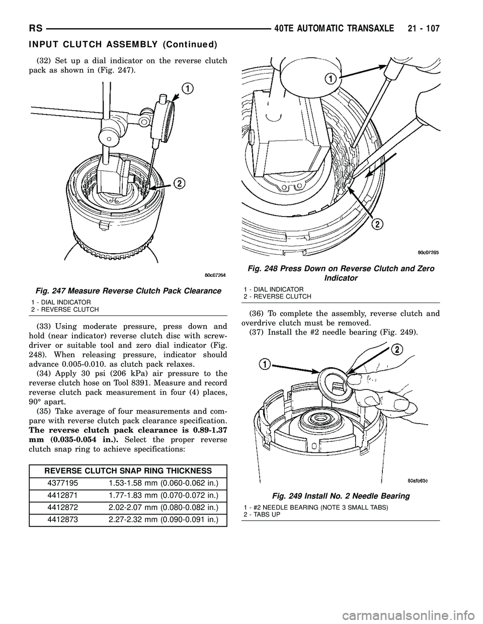
(32) Set up a dial indicator on the reverse clutch
pack as shown in (Fig. 247).
(33) Using moderate pressure, press down and
hold (near indicator) reverse clutch disc with screw-
driver or suitable tool and zero dial indicator (Fig.
248). When releasing pressure, indicator should
advance 0.005-0.010. as clutch pack relaxes.
(34) Apply 30 psi (206 kPa) air pressure to the
reverse clutch hose on Tool 8391. Measure and record
reverse clutch pack measurement in four (4) places,
90É apart.
(35) Take average of four measurements and com-
pare with reverse clutch pack clearance specification.
The reverse clutch pack clearance is 0.89-1.37
mm (0.035-0.054 in.).Select the proper reverse
clutch snap ring to achieve specifications:
REVERSE CLUTCH SNAP RING THICKNESS
4377195 1.53-1.58 mm (0.060-0.062 in.)
4412871 1.77-1.83 mm (0.070-0.072 in.)
4412872 2.02-2.07 mm (0.080-0.082 in.)
4412873 2.27-2.32 mm (0.090-0.091 in.)(36) To complete the assembly, reverse clutch and
overdrive clutch must be removed.
(37) Install the #2 needle bearing (Fig. 249).
Fig. 247 Measure Reverse Clutch Pack Clearance
1 - DIAL INDICATOR
2 - REVERSE CLUTCH
Fig. 248 Press Down on Reverse Clutch and Zero
Indicator
1 - DIAL INDICATOR
2 - REVERSE CLUTCH
Fig. 249 Install No. 2 Needle Bearing
1 - #2 NEEDLE BEARING (NOTE 3 SMALL TABS)
2 - TABS UP
RS40TE AUTOMATIC TRANSAXLE21 - 107
INPUT CLUTCH ASSEMBLY (Continued)
Page 1569 of 2339

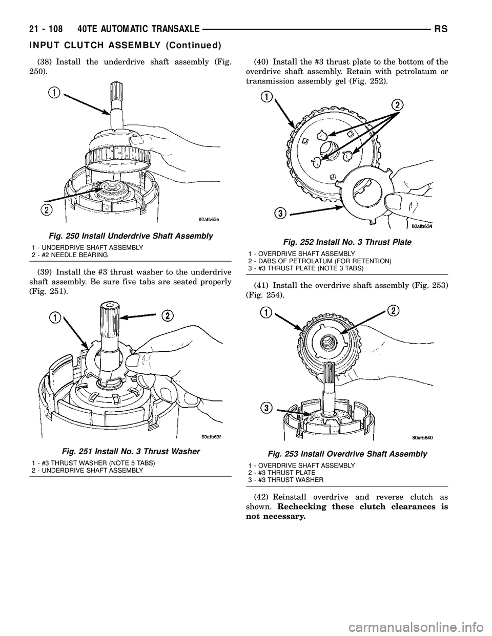
(38) Install the underdrive shaft assembly (Fig.
250).
(39) Install the #3 thrust washer to the underdrive
shaft assembly. Be sure five tabs are seated properly
(Fig. 251).(40) Install the #3 thrust plate to the bottom of the
overdrive shaft assembly. Retain with petrolatum or
transmission assembly gel (Fig. 252).
(41) Install the overdrive shaft assembly (Fig. 253)
(Fig. 254).
(42) Reinstall overdrive and reverse clutch as
shown.Rechecking these clutch clearances is
not necessary.
Fig. 250 Install Underdrive Shaft Assembly
1 - UNDERDRIVE SHAFT ASSEMBLY
2 - #2 NEEDLE BEARING
Fig. 251 Install No. 3 Thrust Washer
1 - #3 THRUST WASHER (NOTE 5 TABS)
2 - UNDERDRIVE SHAFT ASSEMBLY
Fig. 252 Install No. 3 Thrust Plate
1 - OVERDRIVE SHAFT ASSEMBLY
2 - DABS OF PETROLATUM (FOR RETENTION)
3 - #3 THRUST PLATE (NOTE 3 TABS)
Fig. 253 Install Overdrive Shaft Assembly
1 - OVERDRIVE SHAFT ASSEMBLY
2 - #3 THRUST PLATE
3 - #3 THRUST WASHER
21 - 108 40TE AUTOMATIC TRANSAXLERS
INPUT CLUTCH ASSEMBLY (Continued)
Page 1570 of 2339
Fig. 254 Overdrive/Underdrive Shafts
1 - OVERDRIVE SHAFT
2 - #3 THRUST PLATE (3 TABS)
3 - #3 THRUST WASHER (5 TABS)4 - UNDERDRIVE SHAFT
5 - #2 NEEDLE BEARING (3 TABS)
6 - INPUT CLUTCH ASSEMBLY
RS40TE AUTOMATIC TRANSAXLE21 - 109
INPUT CLUTCH ASSEMBLY (Continued)
Page 1623 of 2339
(20) Remove #1 needle bearing (Fig. 34).
(21) Remove input clutch assembly (Fig. 35).(22) Remove #4 thrust plate (Fig. 36).
(23) Remove front sun gear assembly and #4
thrust washer (Fig. 37).
Fig. 34 Remove Caged Needle Bearing
1 - #1 CAGED NEEDLE BEARING
2 - NOTE: TANGED SIDE OUT
Fig. 35 Remove Input Clutch Assembly
1 - INPUT CLUTCH ASSEMBLY
2 - #4 THRUST WASHER
Fig. 36 No. 4 Thrust Plate
1 - OVERDRIVE SHAFT ASSEMBLY
2 - #4 THRUST PLATE (SELECT)
3 - 3 DABS OF PETROLATUM FOR RETENTION
Fig. 37 Remove Front Sun Gear Assembly
1 - FRONT SUN GEAR ASSEMBLY
2 - #4 THRUST WASHER (FOUR TABS)
21 - 162 41TE AUTOMATIC TRANSAXLERS
41TE AUTOMATIC TRANSAXLE (Continued)
Page 1624 of 2339

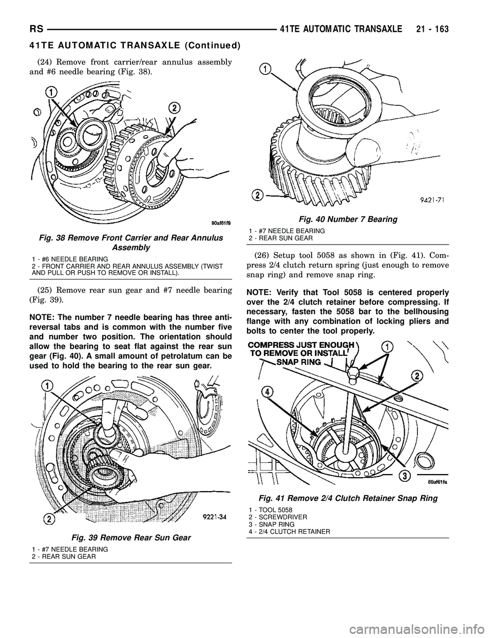
(24) Remove front carrier/rear annulus assembly
and #6 needle bearing (Fig. 38).
(25) Remove rear sun gear and #7 needle bearing
(Fig. 39).
NOTE: The number 7 needle bearing has three anti-
reversal tabs and is common with the number five
and number two position. The orientation should
allow the bearing to seat flat against the rear sun
gear (Fig. 40). A small amount of petrolatum can be
used to hold the bearing to the rear sun gear.(26) Setup tool 5058 as shown in (Fig. 41). Com-
press 2/4 clutch return spring (just enough to remove
snap ring) and remove snap ring.
NOTE: Verify that Tool 5058 is centered properly
over the 2/4 clutch retainer before compressing. If
necessary, fasten the 5058 bar to the bellhousing
flange with any combination of locking pliers and
bolts to center the tool properly.
Fig. 38 Remove Front Carrier and Rear Annulus
Assembly
1 - #6 NEEDLE BEARING
2 - FRONT CARRIER AND REAR ANNULUS ASSEMBLY (TWIST
AND PULL OR PUSH TO REMOVE OR INSTALL).
Fig. 39 Remove Rear Sun Gear
1 - #7 NEEDLE BEARING
2 - REAR SUN GEAR
Fig. 40 Number 7 Bearing
1 - #7 NEEDLE BEARING
2 - REAR SUN GEAR
Fig. 41 Remove 2/4 Clutch Retainer Snap Ring
1 - TOOL 5058
2 - SCREWDRIVER
3 - SNAP RING
4 - 2/4 CLUTCH RETAINER
RS41TE AUTOMATIC TRANSAXLE21 - 163
41TE AUTOMATIC TRANSAXLE (Continued)