Page 1643 of 2339
(23) Bend tabs on strap up against flats of bolts
(Fig. 110).
(24) Install transfer shaft bearing cone using Tool
6052 (Fig. 111).(25) Install bearing cup and oil baffle to transfer
shaft (Fig. 112).
(26) Using Tool 5049A, install transfer shaft (Fig.
113).
Fig. 110 Bend Tabs On Strap Up Against Flats Of
Bolts
1 - RETAINING STRAP TABS
2 - RETAINING STRAP
3 - STIRRUP
Fig. 111 Install Transfer Shaft Bearing Cone
1 - TOOL 6052
2 - NEW BEARING CONE
3 - TRANSFER SHAFT
4 - ARBOR PRESS RAM
Fig. 112 Install Bearing Cup to Shaft
1 - BEARING CUP
2 - BEARING CONE
3 - TRANSFER SHAFT
4 - OIL BAFFLE
5 - O-RING
Fig. 113 Install Transfer Shaft
1 - SPECIAL TOOL 5049±A
2 - TRANSFER SHAFT
3 - OUTPUT GEAR
21 - 182 41TE AUTOMATIC TRANSAXLERS
41TE AUTOMATIC TRANSAXLE (Continued)
Page 1651 of 2339

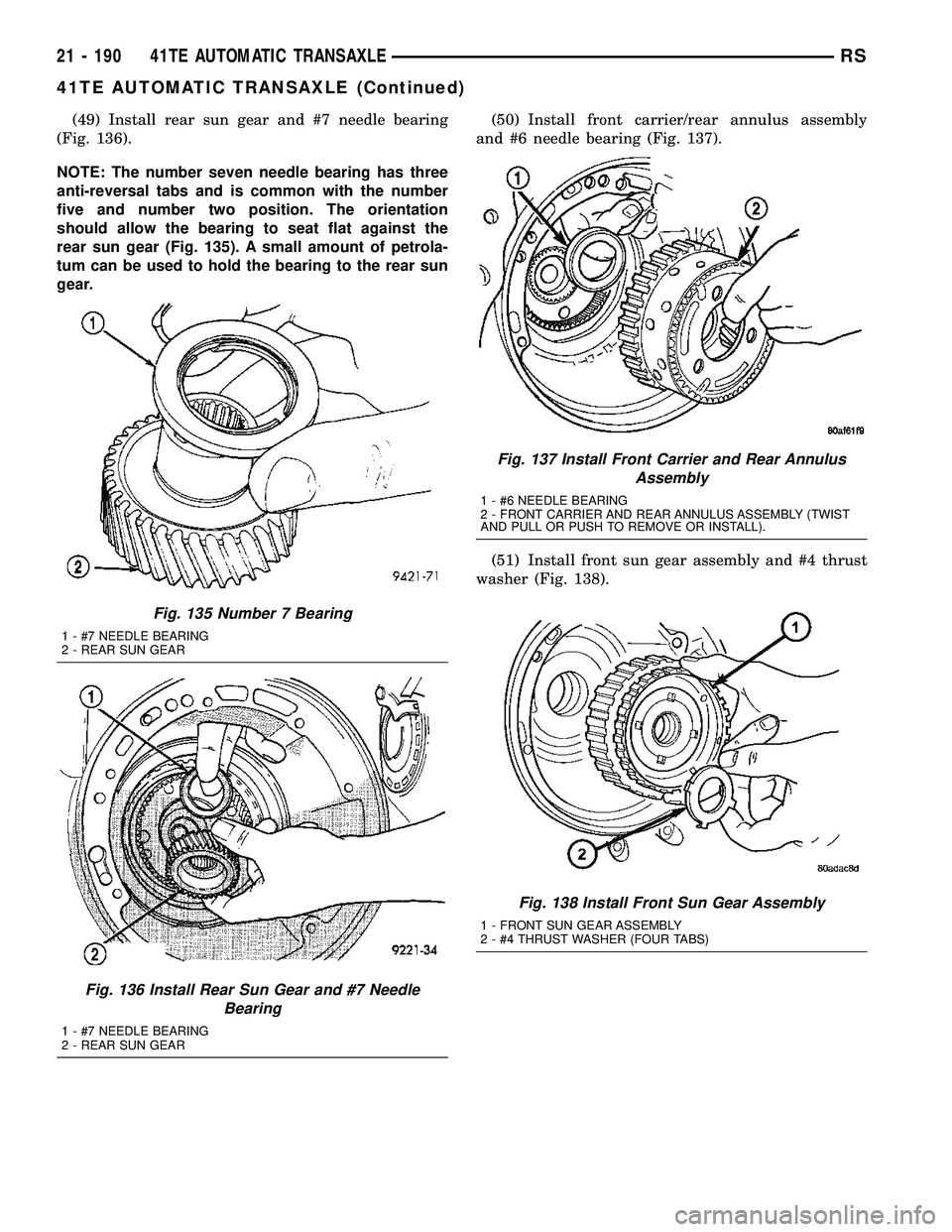
(49) Install rear sun gear and #7 needle bearing
(Fig. 136).
NOTE: The number seven needle bearing has three
anti-reversal tabs and is common with the number
five and number two position. The orientation
should allow the bearing to seat flat against the
rear sun gear (Fig. 135). A small amount of petrola-
tum can be used to hold the bearing to the rear sun
gear.(50) Install front carrier/rear annulus assembly
and #6 needle bearing (Fig. 137).
(51) Install front sun gear assembly and #4 thrust
washer (Fig. 138).
Fig. 135 Number 7 Bearing
1 - #7 NEEDLE BEARING
2 - REAR SUN GEAR
Fig. 136 Install Rear Sun Gear and #7 Needle
Bearing
1 - #7 NEEDLE BEARING
2 - REAR SUN GEAR
Fig. 137 Install Front Carrier and Rear Annulus
Assembly
1 - #6 NEEDLE BEARING
2 - FRONT CARRIER AND REAR ANNULUS ASSEMBLY (TWIST
AND PULL OR PUSH TO REMOVE OR INSTALL).
Fig. 138 Install Front Sun Gear Assembly
1 - FRONT SUN GEAR ASSEMBLY
2 - #4 THRUST WASHER (FOUR TABS)
21 - 190 41TE AUTOMATIC TRANSAXLERS
41TE AUTOMATIC TRANSAXLE (Continued)
Page 1652 of 2339

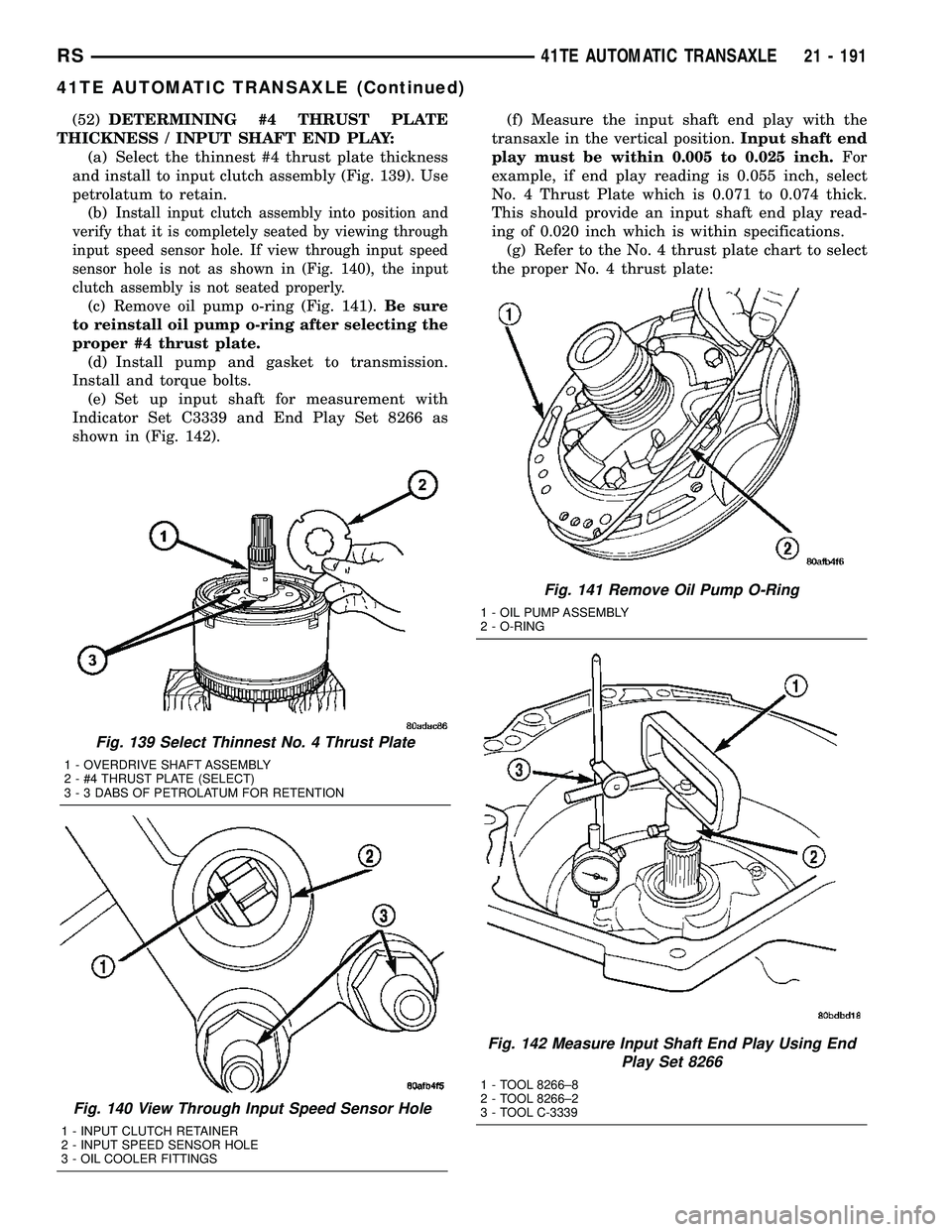
(52)DETERMINING #4 THRUST PLATE
THICKNESS / INPUT SHAFT END PLAY:
(a) Select the thinnest #4 thrust plate thickness
and install to input clutch assembly (Fig. 139). Use
petrolatum to retain.
(b)
Install input clutch assembly into position and
verify that it is completely seated by viewing through
input speed sensor hole. If view through input speed
sensor hole is not as shown in (Fig. 140), the input
clutch assembly is not seated properly.
(c) Remove oil pump o-ring (Fig. 141).Be sure
to reinstall oil pump o-ring after selecting the
proper #4 thrust plate.
(d) Install pump and gasket to transmission.
Install and torque bolts.
(e) Set up input shaft for measurement with
Indicator Set C3339 and End Play Set 8266 as
shown in (Fig. 142).(f) Measure the input shaft end play with the
transaxle in the vertical position.Input shaft end
play must be within 0.005 to 0.025 inch.For
example, if end play reading is 0.055 inch, select
No. 4 Thrust Plate which is 0.071 to 0.074 thick.
This should provide an input shaft end play read-
ing of 0.020 inch which is within specifications.
(g) Refer to the No. 4 thrust plate chart to select
the proper No. 4 thrust plate:
Fig. 139 Select Thinnest No. 4 Thrust Plate
1 - OVERDRIVE SHAFT ASSEMBLY
2 - #4 THRUST PLATE (SELECT)
3 - 3 DABS OF PETROLATUM FOR RETENTION
Fig. 140 View Through Input Speed Sensor Hole
1 - INPUT CLUTCH RETAINER
2 - INPUT SPEED SENSOR HOLE
3 - OIL COOLER FITTINGS
Fig. 141 Remove Oil Pump O-Ring
1 - OIL PUMP ASSEMBLY
2 - O-RING
Fig. 142 Measure Input Shaft End Play Using End
Play Set 8266
1 - TOOL 8266±8
2 - TOOL 8266±2
3 - TOOL C-3339
RS41TE AUTOMATIC TRANSAXLE21 - 191
41TE AUTOMATIC TRANSAXLE (Continued)
Page 1686 of 2339
(3) Install both pinion gears and washers to case,
while orientating washer tabs to notch in case (Fig.
190).
(4) Install pinion shaft (Fig. 191).(5) Install side gear to case (Fig. 192).
(6) Install side gear thrust washer to case (Fig.
193).
Fig. 190 Pinion Gear and Washer Installation
1 - PINION GEAR
2 - TABBED WASHER
3 - LOCATING TAB
4 - NOTCH
Fig. 191 Pinion Shaft Installation
1 - PINION SHAFT
Fig. 192 Side Gear Installation
1 - DIFFERENTIAL SIDE GEAR
Fig. 193 Side Gear Thrust Washer
1 - SIDE GEAR THRUST WASHER
RS41TE AUTOMATIC TRANSAXLE21 - 225
FINAL DRIVE (Continued)
Page 1701 of 2339
(10) Remove and inspect OD and UD Shafts, as
well as #3 thrust washer and plate, and #2 needle
bearing (Fig. 226).
Fig. 226 Overdrive/Underdrive Shafts
1 - OVERDRIVE SHAFT
2 - #3 THRUST PLATE (3 TABS)
3 - #3 THRUST WASHER (5 TABS)4 - UNDERDRIVE SHAFT
5 - #2 NEEDLE BEARING (3 TABS)
6 - INPUT CLUTCH ASSEMBLY
21 - 240 41TE AUTOMATIC TRANSAXLERS
INPUT CLUTCH ASSEMBLY (Continued)
Page 1704 of 2339

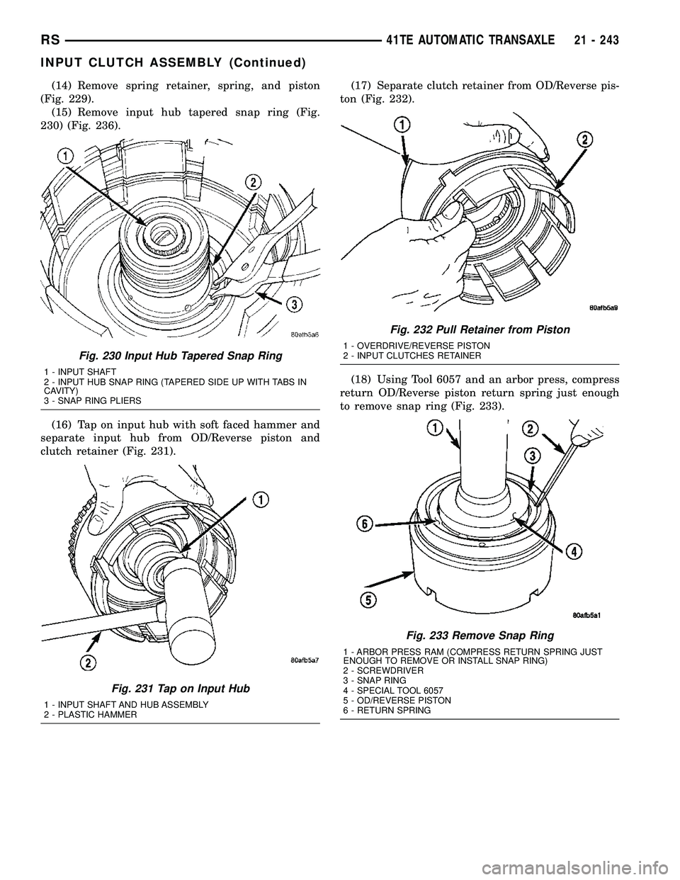
(14) Remove spring retainer, spring, and piston
(Fig. 229).
(15) Remove input hub tapered snap ring (Fig.
230) (Fig. 236).
(16) Tap on input hub with soft faced hammer and
separate input hub from OD/Reverse piston and
clutch retainer (Fig. 231).(17) Separate clutch retainer from OD/Reverse pis-
ton (Fig. 232).
(18) Using Tool 6057 and an arbor press, compress
return OD/Reverse piston return spring just enough
to remove snap ring (Fig. 233).
Fig. 230 Input Hub Tapered Snap Ring
1 - INPUT SHAFT
2 - INPUT HUB SNAP RING (TAPERED SIDE UP WITH TABS IN
CAVITY)
3 - SNAP RING PLIERS
Fig. 231 Tap on Input Hub
1 - INPUT SHAFT AND HUB ASSEMBLY
2 - PLASTIC HAMMER
Fig. 232 Pull Retainer from Piston
1 - OVERDRIVE/REVERSE PISTON
2 - INPUT CLUTCHES RETAINER
Fig. 233 Remove Snap Ring
1 - ARBOR PRESS RAM (COMPRESS RETURN SPRING JUST
ENOUGH TO REMOVE OR INSTALL SNAP RING)
2 - SCREWDRIVER
3 - SNAP RING
4 - SPECIAL TOOL 6057
5 - OD/REVERSE PISTON
6 - RETURN SPRING
RS41TE AUTOMATIC TRANSAXLE21 - 243
INPUT CLUTCH ASSEMBLY (Continued)
Page 1708 of 2339
(4) Install the OD/Reverse piston assembly to the
input clutch retainer as shown in (Fig. 241).
(5) Install the input hub/shaft assy. to the OD/Re-
verse piston/clutch retainer assy. (Fig. 242).(6) Install input hub tapered snap ring (Fig. 243)
(Fig. 244).
Fig. 241 Install OD/Reverse Piston
1 - PUSH DOWN TO INSTALL OVERDRIVE/REVERSE PISTON
2 - INPUT CLUTCHES RETAINER
Fig. 242 Install Input Shaft Hub Assembly
1 - PUSH DOWN TO INSTALL INPUT SHAFT HUB ASSEMBLY
(ROTATE TO ALIGN SPLINES)
2 - OD/REV. PISTON
Fig. 243 Install Input Hub Tapered Snap Ring
1 - INPUT SHAFT
2 - INPUT HUB SNAP RING (TAPERED SIDE UP WITH TABS IN
CAVITY)
3 - SNAP RING PLIERS
RS41TE AUTOMATIC TRANSAXLE21 - 247
INPUT CLUTCH ASSEMBLY (Continued)
Page 1719 of 2339

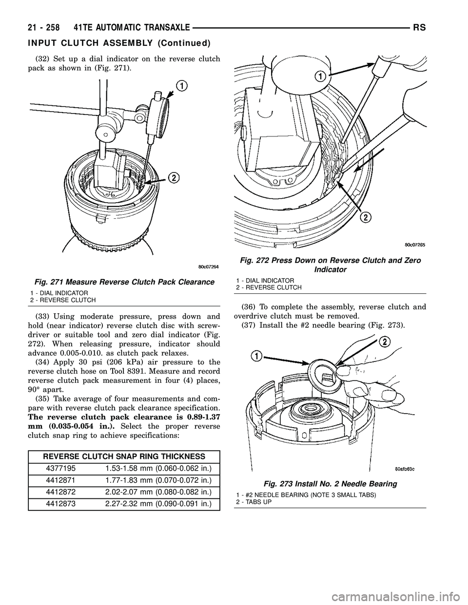
(32) Set up a dial indicator on the reverse clutch
pack as shown in (Fig. 271).
(33) Using moderate pressure, press down and
hold (near indicator) reverse clutch disc with screw-
driver or suitable tool and zero dial indicator (Fig.
272). When releasing pressure, indicator should
advance 0.005-0.010. as clutch pack relaxes.
(34) Apply 30 psi (206 kPa) air pressure to the
reverse clutch hose on Tool 8391. Measure and record
reverse clutch pack measurement in four (4) places,
90É apart.
(35) Take average of four measurements and com-
pare with reverse clutch pack clearance specification.
The reverse clutch pack clearance is 0.89-1.37
mm (0.035-0.054 in.).Select the proper reverse
clutch snap ring to achieve specifications:
REVERSE CLUTCH SNAP RING THICKNESS
4377195 1.53-1.58 mm (0.060-0.062 in.)
4412871 1.77-1.83 mm (0.070-0.072 in.)
4412872 2.02-2.07 mm (0.080-0.082 in.)
4412873 2.27-2.32 mm (0.090-0.091 in.)(36) To complete the assembly, reverse clutch and
overdrive clutch must be removed.
(37) Install the #2 needle bearing (Fig. 273).
Fig. 271 Measure Reverse Clutch Pack Clearance
1 - DIAL INDICATOR
2 - REVERSE CLUTCH
Fig. 272 Press Down on Reverse Clutch and Zero
Indicator
1 - DIAL INDICATOR
2 - REVERSE CLUTCH
Fig. 273 Install No. 2 Needle Bearing
1 - #2 NEEDLE BEARING (NOTE 3 SMALL TABS)
2 - TABS UP
21 - 258 41TE AUTOMATIC TRANSAXLERS
INPUT CLUTCH ASSEMBLY (Continued)