2005 CHRYSLER CARAVAN ABS
[x] Cancel search: ABSPage 1325 of 2339
STANDARD PROCEDURE - INTAKE MANIFOLD
VACUUM PORT REPAIR
The composite intake manifold vacuum ports can
be repaired. Although, if the manifold plenum cham-
ber is damaged or cracked, the manifold must be
replaced.
To repair a broken or damaged vacuum nipple
(port) on the composite intake manifold, perform the
following procedure:
PARTS REQUIRED TOOLS REQUIRED
´ Brass Nipple ± 1/49
O.D. x 1/89pipe thread
(LDP/Speed Control Port)´ Pipe Tap ± 1/89-18
NPT
´ Drill Bit ± 11/329
´ File/Sandpaper
´ Brass Nipple ± 1/29
O.D. x 1/49pipe thread
(Brake Booster Port)´ Pipe Tap ± 1/49-18
NPT
´ Drill Bit ± 7/169
´ File/Sandpaper
NOTE: While performing this procedure, avoid get-
ting the manifold material residue into the plenum
chamber.
(1) File or sand the remaining port back until a
flat surface is obtained (plane normal to nipple (port)
axis).
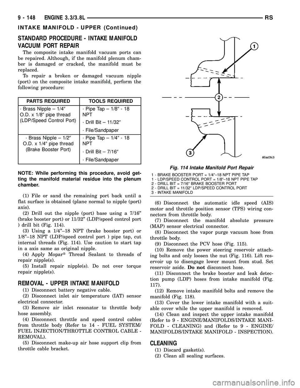
(2) Drill out the nipple (port) base using a 7/16º
(brake booster port) or 11/32º (LDP/speed control port
) drill bit (Fig. 114).
(3) Using a 1/4º±18 NPT (brake booster port) or
1/8º±18 NPT (LDP/speed control port ) pipe tap, cut
internal threads (Fig. 114). Use caution to start tap
in a axis same as original nipple.
(4) Apply MopartThread Sealant to threads of
repair nipple(s).
(5) Install repair nipple(s). Do not over torque
repair nipple(s).
REMOVAL - UPPER INTAKE MANIFOLD
(1) Disconnect battery negative cable.
(2) Disconnect inlet air temperature (IAT) sensor
electrical connector.
(3) Remove air inlet resonator to throttle body
hose assembly.
(4) Disconnect throttle and speed control cables
from throttle body (Refer to 14 - FUEL SYSTEM/
FUEL INJECTION/THROTTLE CONTROL CABLE -
REMOVAL).
(5) Disconnect make-up air hose support clip from
throttle cable bracket.(6) Disconnect the automatic idle speed (AIS)
motor and throttle position sensor (TPS) wiring con-
nectors from throttle body.
(7) Disconnect the manifold absolute pressure
(MAP) sensor electrical connector.
(8) Disconnect the vapor purge vacuum hose from
throttle body.
(9) Disconnect the PCV hose (Fig. 115).
(10) Remove the power steering reservoir attach-
ing bolts and only loosen the nut (Fig. 116). Lift res-
ervoir up to disengage lower mount from stud. Set
reservoir aside.Do notdisconnect hose.
(11) Disconnect the brake booster and leak detec-
tion pump (LDP) hoses from intake manifold (Fig.
117).
(12) Remove intake manifold bolts and remove the
manifold (Fig. 118).
(13) Cover the lower intake manifold with a suit-
able cover while the upper manifold is removed.
(14) Clean and inspect the upper intake manifold
(Refer to 9 - ENGINE/MANIFOLDS/INTAKE MANI-
FOLD - CLEANING) and (Refer to 9 - ENGINE/
MANIFOLDS/INTAKE MANIFOLD - INSPECTION).
CLEANING
(1) Discard gasket(s).
(2) Clean all sealing surfaces.
Fig. 114 Intake Manifold Port Repair
1 - BRAKE BOOSTER PORT = 1/49±18 NPT PIPE TAP
1 - LDP/SPEED CONTROL PORT = 1/89±18 NPT PIPE TAP
2 - DRILL BIT = 7/169BRAKE BOOSTER PORT
2 - DRILL BIT = 11/329LDP/SPEED CONTROL PORT
3 - INTAKE MANIFOLD
9 - 148 ENGINE 3.3/3.8LRS
INTAKE MANIFOLD - UPPER (Continued)
Page 1352 of 2339
REAR BUMPER
REINFORCEMENT
REMOVAL
(1) Remove rear bumper fascia. (Refer to 13 -
FRAMES & BUMPERS/BUMPERS/REAR FASCIA -
REMOVAL)
(2) Support rear bumper reinforcement on a suit-
able lifting device.
(3) Remove the four nuts attaching rear bumper
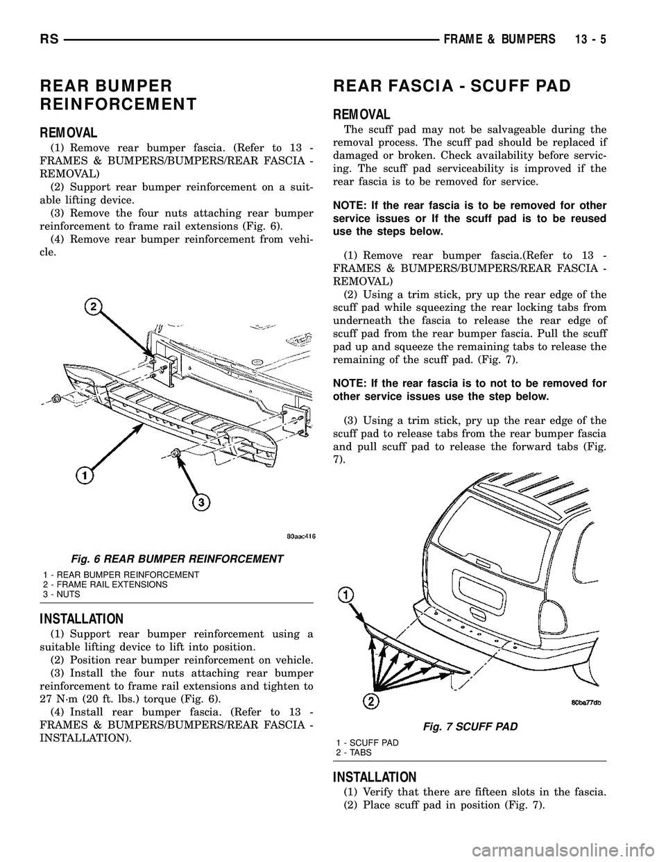
reinforcement to frame rail extensions (Fig. 6).
(4) Remove rear bumper reinforcement from vehi-
cle.
INSTALLATION
(1) Support rear bumper reinforcement using a
suitable lifting device to lift into position.
(2) Position rear bumper reinforcement on vehicle.
(3) Install the four nuts attaching rear bumper
reinforcement to frame rail extensions and tighten to
27 N´m (20 ft. lbs.) torque (Fig. 6).
(4) Install rear bumper fascia. (Refer to 13 -
FRAMES & BUMPERS/BUMPERS/REAR FASCIA -
INSTALLATION).
REAR FASCIA - SCUFF PAD
REMOVAL
The scuff pad may not be salvageable during the
removal process. The scuff pad should be replaced if
damaged or broken. Check availability before servic-
ing. The scuff pad serviceability is improved if the
rear fascia is to be removed for service.
NOTE: If the rear fascia is to be removed for other
service issues or If the scuff pad is to be reused
use the steps below.
(1) Remove rear bumper fascia.(Refer to 13 -
FRAMES & BUMPERS/BUMPERS/REAR FASCIA -
REMOVAL)
(2) Using a trim stick, pry up the rear edge of the
scuff pad while squeezing the rear locking tabs from
underneath the fascia to release the rear edge of
scuff pad from the rear bumper fascia. Pull the scuff
pad up and squeeze the remaining tabs to release the
remaining of the scuff pad. (Fig. 7).
NOTE: If the rear fascia is to not to be removed for
other service issues use the step below.
(3) Using a trim stick, pry up the rear edge of the
scuff pad to release tabs from the rear bumper fascia
and pull scuff pad to release the forward tabs (Fig.
7).
INSTALLATION
(1) Verify that there are fifteen slots in the fascia.
(2) Place scuff pad in position (Fig. 7).
Fig. 6 REAR BUMPER REINFORCEMENT
1 - REAR BUMPER REINFORCEMENT
2 - FRAME RAIL EXTENSIONS
3 - NUTS
Fig. 7 SCUFF PAD
1 - SCUFF PAD
2 - TABS
RSFRAME & BUMPERS13-5
Page 1353 of 2339
(3) Align and insert the center forward tab.
(4) Align the remaining tabs and press into the
slots, starting in the center and working outboard.
(5) Assure all tabs are fully engaged into the fas-
cia.
(6) If rear bumper fascia has been removed install.
(Refer to 13 - FRAME & BUMPERS/BUMPERS/
REAR FASCIA - INSTALLATION).
FRAME
SPECIFICATIONS
SPECIFICATIONS - FRAME DIMENSIONS
Frame dimensions are listed in metric scale. All
dimensions are from center to center of PrincipalLocating Point (PLP), or from center to center of PLP
and fastener location.
VEHICLE PREPARATION
Position the vehicle on a frame alignment rack,
refer to instructions provided with equipment being
used. Adjust the vehicle PLP heights to the specified
dimension above the work surface (datum line). Ver-
tical dimensions can be taken from the datum line to
the locations indicated were applicable.
INDEX
DESCRIPTION FIGURE
CROSSMEMBER DIMENSIONS 8
ENGINE BOX - TOP VIEW 9
ENGINE COMPARTMENT AND FRAME RAIL - SIDE VIEW 10
FULL VEHICLE - BOTTOM VIEW 11
13 - 6 FRAME & BUMPERSRS
REAR FASCIA - SCUFF PAD (Continued)
Page 1373 of 2339
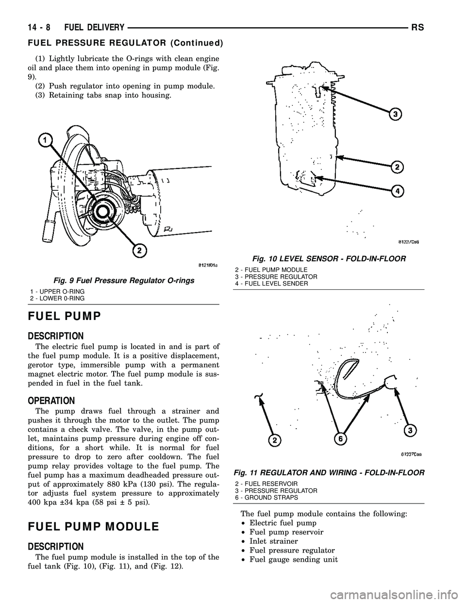
(1) Lightly lubricate the O-rings with clean engine
oil and place them into opening in pump module (Fig.
9).
(2) Push regulator into opening in pump module.
(3) Retaining tabs snap into housing.
FUEL PUMP
DESCRIPTION
The electric fuel pump is located in and is part of
the fuel pump module. It is a positive displacement,
gerotor type, immersible pump with a permanent
magnet electric motor. The fuel pump module is sus-
pended in fuel in the fuel tank.
OPERATION
The pump draws fuel through a strainer and
pushes it through the motor to the outlet. The pump
contains a check valve. The valve, in the pump out-
let, maintains pump pressure during engine off con-
ditions, for a short while. It is normal for fuel
pressure to drop to zero after cooldown. The fuel
pump relay provides voltage to the fuel pump. The
fuel pump has a maximum deadheaded pressure out-
put of approximately 880 kPa (130 psi). The regula-
tor adjusts fuel system pressure to approximately
400 kpa 34 kpa (58 psi 5 psi).
FUEL PUMP MODULE
DESCRIPTION
The fuel pump module is installed in the top of the
fuel tank (Fig. 10), (Fig. 11), and (Fig. 12).The fuel pump module contains the following:
²Electric fuel pump
²Fuel pump reservoir
²Inlet strainer
²Fuel pressure regulator
²Fuel gauge sending unit
Fig. 9 Fuel Pressure Regulator O-rings
1 - UPPER O-RING
2 - LOWER 0-RING
Fig. 10 LEVEL SENSOR - FOLD-IN-FLOOR
2 - FUEL PUMP MODULE
3 - PRESSURE REGULATOR
4 - FUEL LEVEL SENDER
Fig. 11 REGULATOR AND WIRING - FOLD-IN-FLOOR
2 - FUEL RESERVOIR
3 - PRESSURE REGULATOR
6 - GROUND STRAPS
14 - 8 FUEL DELIVERYRS
FUEL PRESSURE REGULATOR (Continued)
Page 1376 of 2339
FUEL RAIL
REMOVAL
REMOVAL - 2.4L
(1) Perform fuel system pressure release procedure
before servicing or starting repairs.Refer to
Fuel System Pressure Release Procedure in this sec-
tion.
(2) Disconnect negative cable from battery.
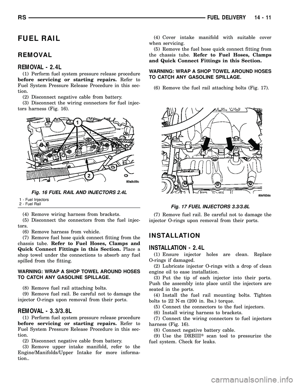
(3) Disconnect the wiring connectors for fuel injec-
tors harness (Fig. 16).
(4) Remove wiring harness from brackets.
(5) Disconnect the connectors from the fuel injec-
tors.
(6) Remove harness from vehicle.
(7) Remove fuel hose quick connect fitting from the
chassis tube.Refer to Fuel Hoses, Clamps and
Quick Connect Fittings in this Section.Place a
shop towel under the connections to absorb any fuel
spilled from the fitting.
WARNING: WRAP A SHOP TOWEL AROUND HOSES
TO CATCH ANY GASOLINE SPILLAGE.
(8) Remove fuel rail attaching bolts.
(9) Remove fuel rail. Be careful not to damage the
injector O-rings upon removal from their ports.
REMOVAL - 3.3/3.8L
(1) Perform fuel system pressure release procedure
before servicing or starting repairs.Refer to
Fuel System Pressure Release Procedure in this sec-
tion.
(2) Disconnect negative cable from battery.
(3) Remove upper intake manifold, refer to the
Engine/Manifolds/Upper Intake for more informa-
tion..(4) Cover intake manifold with suitable cover
when servicing.
(5) Remove the fuel hose quick connect fitting from
the chassis tube.Refer to Fuel Hoses, Clamps
and Quick Connect Fittings in this Section.
WARNING: WRAP A SHOP TOWEL AROUND HOSES
TO CATCH ANY GASOLINE SPILLAGE.
(6) Remove the fuel rail attaching bolts (Fig. 17).
(7) Remove fuel rail. Be careful not to damage the
injector O-rings upon removal from their ports.
INSTALLATION
INSTALLATION - 2.4L
(1) Ensure injector holes are clean. Replace
O-rings if damaged.
(2) Lubricate injector O-rings with a drop of clean
engine oil to ease installation.
(3) Put the tip of each injector into their ports.
Push the assembly into place until the injectors are
seated in the ports.
(4) Install the fuel rail mounting bolts. Tighten
bolts to 22 N´m (200 in. lbs.) torque.
(5) Connect the connectors to the fuel injectors.
(6) Install wiring harness to brackets.
(7) Connect the wiring connectors to fuel injectors
harness (Fig. 16).
(8) Connect negative battery cable.
(9) Use the DRBIIItscan tool to pressurize the
fuel system. Check for leaks.
Fig. 16 FUEL RAIL AND INJECTORS 2.4L
1 - Fuel Injectors
2 - Fuel Rail
Fig. 17 FUEL INJECTORS 3.3/3.8L
RSFUEL DELIVERY14-11
Page 1377 of 2339
INSTALLATION - 3.3/3.8L
(1) Ensure injector holes are clean. Replace
O-rings if damaged.
(2) Lubricate injector O-rings with a drop of clean
engine oil to ease installation.
(3) Put the tip of each injector into their ports.
Push the assembly into place until the injectors are
seated in the ports.
(4) Install the fuel rail mounting bolts. Tighten
bolts to 22 N´m (200 in. lbs.) torque.
(5) Remove covering on lower intake manifold and
clean surface.
(6) Install the Upper Intake Manifold, refer to
Engine/Manifolds/Upper Intake for more information.
(7) Install fuel hose quick connector fitting to chas-
sis tubes.Refer to Fuel Hoses, Clamps and
Quick Connect Fittings in this Section.Push the
fitting onto the chassis tube until it clicks into place.
Pull on the fitting to ensure complete insertion.
(8) Connect negative cable to battery.
(9) Use the DRBIIItscan tool to pressurize the
fuel system. Check for leaks.
FUEL TANK
DESCRIPTION
The fuel tank is constructed of a plastic material.
Its main functions are for fuel storage and for place-
ment of the fuel pump module. The tank is made
from High density Polyethylene (HDPE) material.If
equipped with ORVR (Onboard Refueling Vapor
Recovery) it has been added to the fuel tank to con-
trol refueling vapor emissions.
OPERATION
All models pass a full 360 degree rollover test
without fuel leakage. To accomplish this, fuel and
vapor flow controls are required for all fuel tank con-
nections.
All models are equipped with either one or two
check valves mounted into the top of the fuel tank (or
pump module).
An evaporation control system is connected to the
check valve(s)/control valve(Refer to 25 - EMIS-
SIONS CONTROL/EVAPORATIVE EMISSIONS/
ORVR - OPERATION) to reduce emissions of fuel
vapors into the atmosphere, when the tank is vented
due to vapor expansion in the tank. When fuel evap-
orates from the fuel tank, vapors pass through vent
hoses or tubes to a charcoal canister where they are
temporarily held. When the engine is running, the
vapors are drawn into the intake manifold. In addi-
tion, fuel vapors produced during vehicle refueling
are allowed to pass through the vent hoses/tubes to
the charcoal canister(s) for temporary storage (priorto being drawn into the intake manifold). All models
are equipped with a self-diagnosing system using a
Leak Detection Pump (LDP) or Natural Vacuum
Leak Detection (NVLD). Refer to the Emission Con-
trol System for additional information.
INLET CHECK VALVE
All vehicles have an inlet check valve on the inside
of the fuel tank at the filler inlet
The valve prevents fuel from splashing back on
customer during vehicle refueling. The valve is a
non-serviceable item.
REMOVAL
REMOVAL
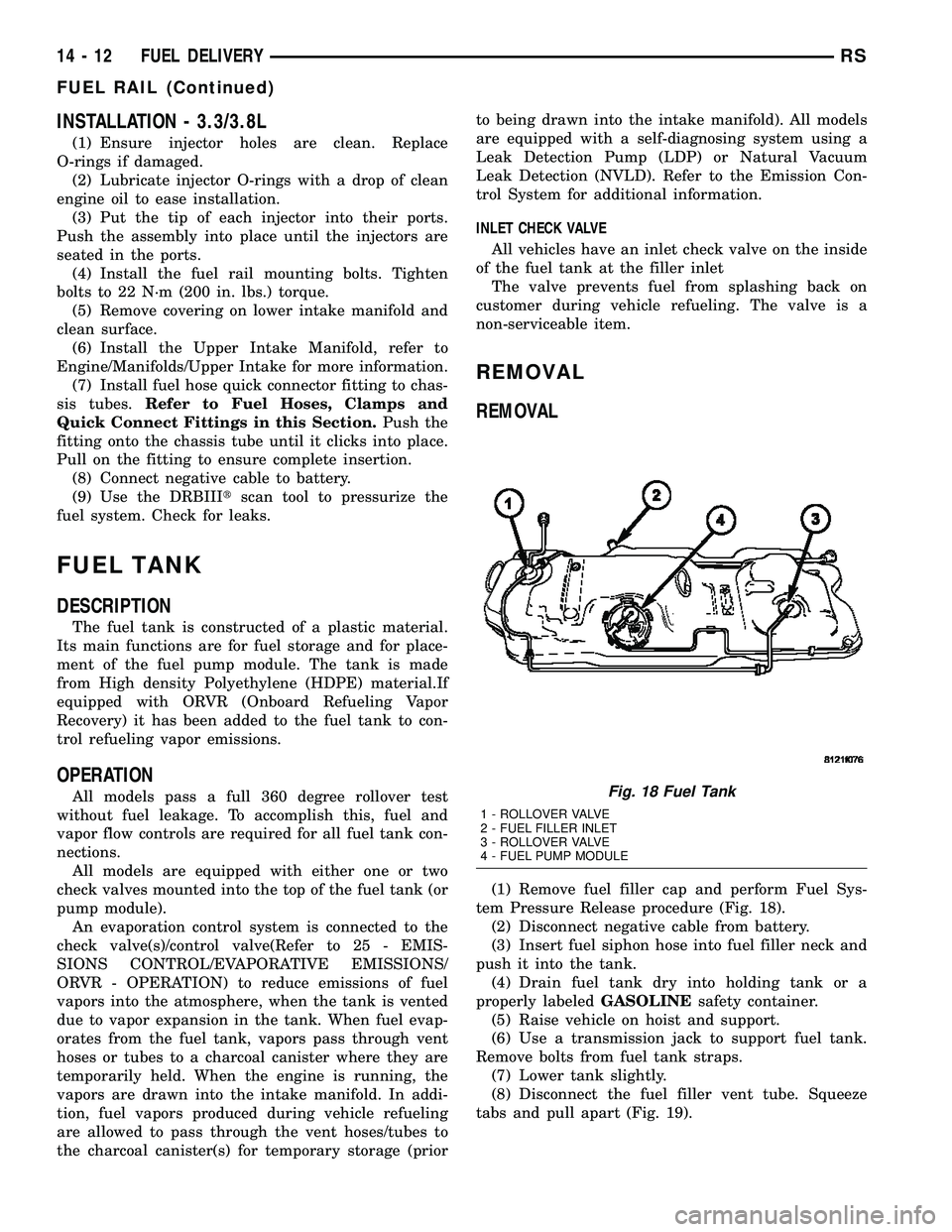
(1) Remove fuel filler cap and perform Fuel Sys-
tem Pressure Release procedure (Fig. 18).
(2) Disconnect negative cable from battery.
(3) Insert fuel siphon hose into fuel filler neck and
push it into the tank.
(4) Drain fuel tank dry into holding tank or a
properly labeledGASOLINEsafety container.
(5) Raise vehicle on hoist and support.
(6) Use a transmission jack to support fuel tank.
Remove bolts from fuel tank straps.
(7) Lower tank slightly.
(8) Disconnect the fuel filler vent tube. Squeeze
tabs and pull apart (Fig. 19).
Fig. 18 Fuel Tank
1 - ROLLOVER VALVE
2 - FUEL FILLER INLET
3 - ROLLOVER VALVE
4 - FUEL PUMP MODULE
14 - 12 FUEL DELIVERYRS
FUEL RAIL (Continued)
Page 1379 of 2339
(5) Use a transmission jack to support fuel tank.
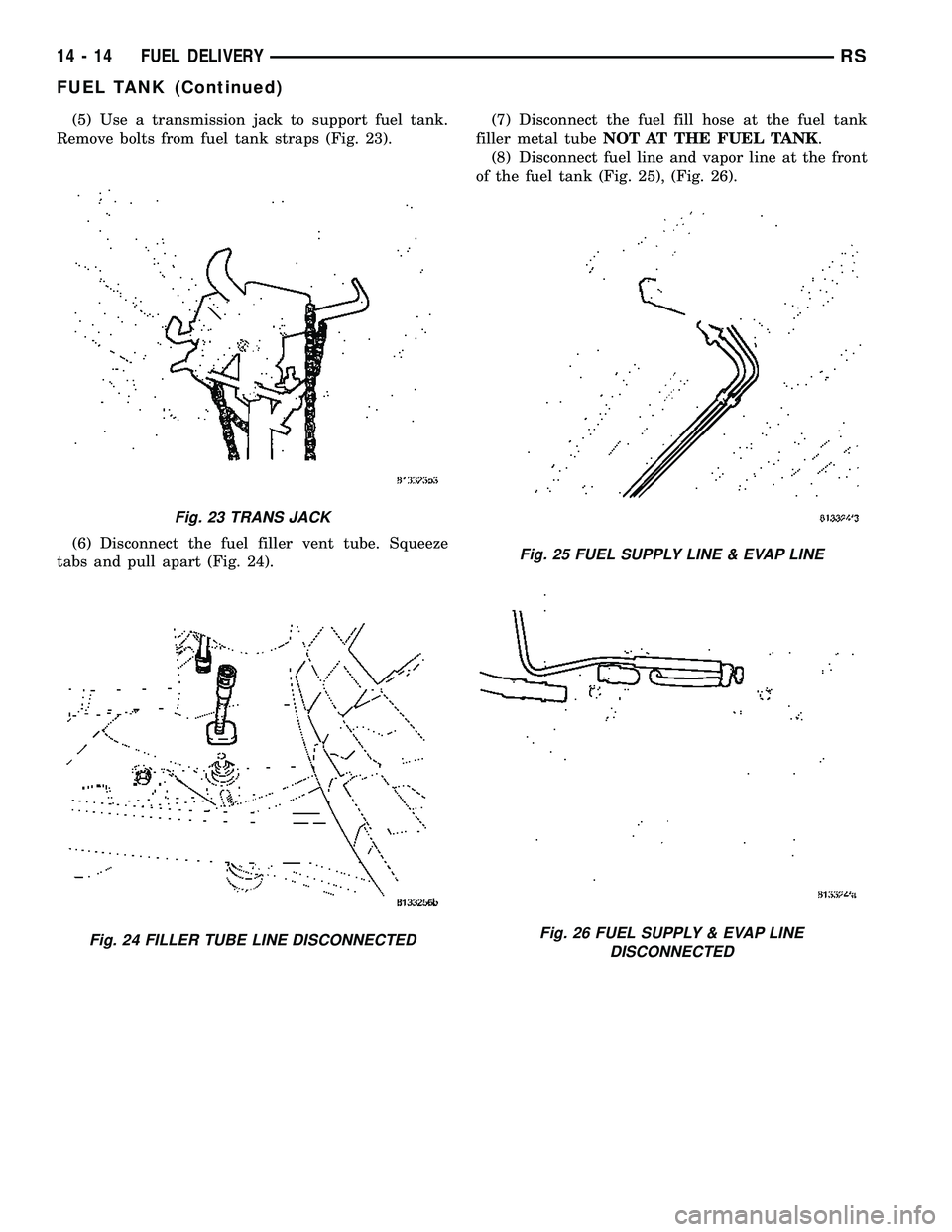
Remove bolts from fuel tank straps (Fig. 23).
(6) Disconnect the fuel filler vent tube. Squeeze
tabs and pull apart (Fig. 24).(7) Disconnect the fuel fill hose at the fuel tank
filler metal tubeNOT AT THE FUEL TANK.
(8) Disconnect fuel line and vapor line at the front
of the fuel tank (Fig. 25), (Fig. 26).
Fig. 23 TRANS JACK
Fig. 24 FILLER TUBE LINE DISCONNECTED
Fig. 25 FUEL SUPPLY LINE & EVAP LINE
Fig. 26 FUEL SUPPLY & EVAP LINE
DISCONNECTED
14 - 14 FUEL DELIVERYRS
FUEL TANK (Continued)
Page 1382 of 2339
(8)For RGDisconnect the vent at the top of the
filler tube.
(9) Remove the ground strap.
(10) Remove filler tube at tank.
INSTALLATION
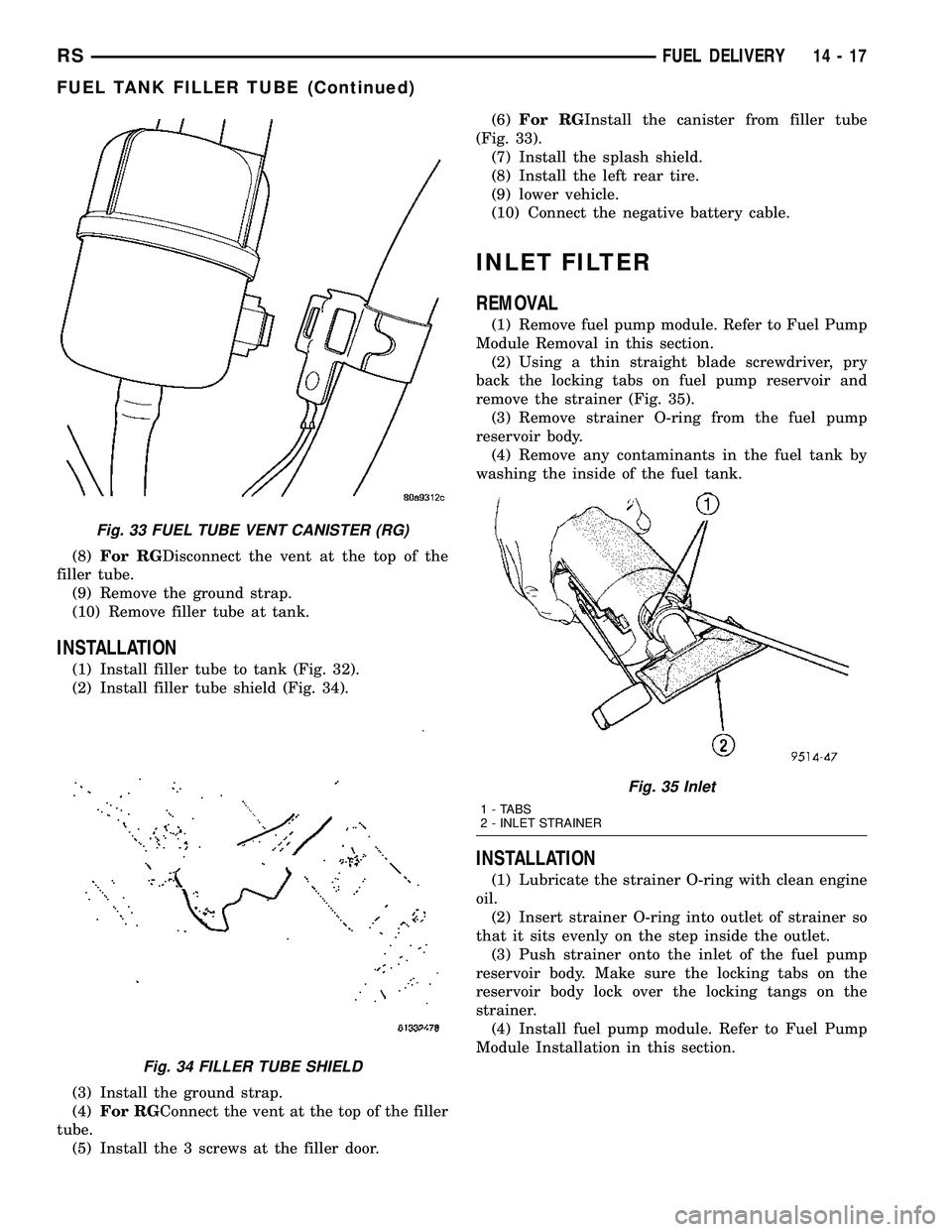
(1) Install filler tube to tank (Fig. 32).
(2) Install filler tube shield (Fig. 34).
(3) Install the ground strap.
(4)For RGConnect the vent at the top of the filler
tube.
(5) Install the 3 screws at the filler door.(6)For RGInstall the canister from filler tube
(Fig. 33).
(7) Install the splash shield.
(8) Install the left rear tire.
(9) lower vehicle.
(10) Connect the negative battery cable.
INLET FILTER
REMOVAL
(1) Remove fuel pump module. Refer to Fuel Pump
Module Removal in this section.
(2) Using a thin straight blade screwdriver, pry
back the locking tabs on fuel pump reservoir and
remove the strainer (Fig. 35).
(3) Remove strainer O-ring from the fuel pump
reservoir body.
(4) Remove any contaminants in the fuel tank by
washing the inside of the fuel tank.
INSTALLATION
(1) Lubricate the strainer O-ring with clean engine
oil.
(2) Insert strainer O-ring into outlet of strainer so
that it sits evenly on the step inside the outlet.
(3) Push strainer onto the inlet of the fuel pump
reservoir body. Make sure the locking tabs on the
reservoir body lock over the locking tangs on the
strainer.
(4) Install fuel pump module. Refer to Fuel Pump
Module Installation in this section.
Fig. 33 FUEL TUBE VENT CANISTER (RG)
Fig. 34 FILLER TUBE SHIELD
Fig. 35 Inlet
1 - TABS
2 - INLET STRAINER
RSFUEL DELIVERY14-17
FUEL TANK FILLER TUBE (Continued)