2005 CHRYSLER CARAVAN ABS
[x] Cancel search: ABSPage 1127 of 2339
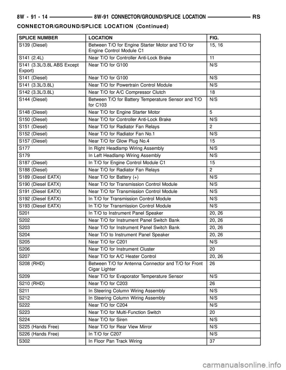
SPLICE NUMBER LOCATION FIG.
S139 (Diesel) Between T/O for Engine Starter Motor and T/O for
Engine Control Module C115, 16
S141 (2.4L) Near T/O for Controller Anti-Lock Brake 11
S141 (3.3L/3.8L ABS Except
Export)Near T/O for G100 N/S
S141 (Diesel) Near T/O for G100 N/S
S141 (3.3L/3.8L) Near T/O for Powertrain Control Module N/S
S142 (3.3L/3.8L) Near T/O for A/C Compressor Clutch 18
S144 (Diesel) Between T/O for Battery Temperature Sensor and T/O
for C103N/S
S148 (Diesel) Near T/O for Engine Starter Motor 5
S150 (Diesel) Near T/O for Controller Anti-Lock Brake N/S
S151 (Diesel) Near T/O for Radiator Fan Relays 2
S152 (Diesel) Near T/O for Radiator Fan No.1 N/S
S157 (Diesel) Near T/O for Glow Plug No.4 15
S177 In Right Headlamp Wiring Assembly N/S
S179 In Left Headlamp Wiring Assembly N/S
S187 (Diesel) In T/O for Engine Control Module C1 15
S188 (Diesel) Near T/O for Radiator Fan Relays 2
S189 (Diesel EATX) Near T/O for Battery (+) N/S
S190 (Diesel EATX) Near T/O for Transmission Control Module N/S
S191 (Diesel EATX) Near T/O for Transmission Control Module N/S
S192 (Diesel EATX) In T/O for Transmission Control Module N/S
S193 (Diesel EATX) In T/O for Transmission Control Module N/S
S201 In T/O to Instrument Panel Speaker 20, 26
S202 Near T/O for Instrument Panel Switch Bank 20, 26
S203 Near T/O for Instrument Panel Switch Bank 20, 26
S204 Near T/O to Instrument Panel Speaker 20, 26
S205 Near T/O for C201 N/S
S206 Near T/O for Instrument Cluster 20
S207 Near T/O for A/C Heater Control 20, 26
S208 (RHD) Between T/O for Antenna Connector and T/O for Front
Cigar Lighter26
S209 Near T/O for Evaporator Temperature Sensor N/S
S210 (RHD) Near T/O for C203 26
S211 In Steering Column Wiring Assembly N/S
S212 In Steering Column Wiring Assembly N/S
S222 Near T/O for C204 N/S
S223 Near T/O for Multi-Function Switch 20
S224 Near T/O for Siren N/S
S225 (Hands Free) Near T/O for Rear View Mirror N/S
S226 (Hands Free) In T/O for C207 N/S
S302 In Floor Pan Track Wiring 37
8W - 91 - 14 8W-91 CONNECTOR/GROUND/SPLICE LOCATIONRS
CONNECTOR/GROUND/SPLICE LOCATION (Continued)
Page 1188 of 2339
(11) Fill engine with specified amount of approved
oil.
(12) Connect negative battery cable.
(13) Start engine and check for any leaks.
FORM-IN-PLACE GASKETS AND SEALERS
There are numerous places where form-in-place
gaskets are used on the engine. Care must be taken
when applying form-in-place gaskets to assure
obtaining the desired results.Do not use form-in-
place gasket material unless specified.Bead size,
continuity, and location are of great importance. Too
thin a bead can result in leakage while too much can
result in spill-over which can break off and obstruct
fluid feed lines. A continuous bead of the proper
width is essential to obtain a leak-free gasket.
There are numerous types of form-in-place gasket
materials that are used in the engine area. Mopart
Engine RTV GEN II, MopartATF-RTV, and Mopart
Gasket Maker gasket materials, each have different
properties and can not be used in place of the other.
MOPARtENGINE RTV GEN IIis used to seal
components exposed to engine oil. This material is a
specially designed black silicone rubber RTV that
retains adhesion and sealing properties when
exposed to engine oil. Moisture in the air causes the
material to cure. This material is available in three
ounce tubes and has a shelf life of one year. After one
year this material will not properly cure. Always
inspect the package for the expiration date before
use.
MOPARtATF RTVis a specifically designed
black silicone rubber RTV that retains adhesion and
sealing properties to seal components exposed to
automatic transmission fluid, engine coolants, and
moisture. This material is available in three ounce
tubes and has a shelf life of one year. After one year
this material will not properly cure. Always inspect
the package for the expiration date before use.
MOPARtGASKET MAKERis an anaerobic type
gasket material. The material cures in the absence of
air when squeezed between two metallic surfaces. It
will not cure if left in the uncovered tube. The
anaerobic material is for use between two machined
surfaces. Do not use on flexible metal flanges.
MOPARtBED PLATE SEALANTis a unique
(green-in-color) anaerobic type gasket material that
is specially made to seal the area between the bed
plate and cylinder block without disturbing the bear-
ing clearance or alignment of these components. The
material cures slowly in the absence of air when
torqued between two metallic surfaces, and will rap-
idly cure when heat is applied.
MOPARtGASKET SEALANTis a slow drying,
permanently soft sealer. This material is recom-
mended for sealing threaded fittings and gasketsagainst leakage of oil and coolant. Can be used on
threaded and machined parts under all tempera-
tures. This material is used on engines with multi-
layer steel (MLS) cylinder head gaskets. This
material also will prevent corrosion. MopartGasket
Sealant is available in a 13 oz. aerosol can or 4oz./16
oz. can w/applicator.
SEALER APPLICATION
MopartGasket Maker material should be applied
sparingly 1 mm (0.040 in.) diameter or less of sealant
to one gasket surface. Be certain the material sur-
rounds each mounting hole. Excess material can eas-
ily be wiped off. Components should be torqued in
place within 15 minutes. The use of a locating dowel
is recommended during assembly to prevent smear-
ing material off the location.
MopartEngine RTV GEN II or ATF RTV gasket
material should be applied in a continuous bead
approximately 3 mm (0.120 in.) in diameter. All
mounting holes must be circled. For corner sealing, a
3.17 or 6.35 mm (1/8 or 1/4 in.) drop is placed in the
center of the gasket contact area. Uncured sealant
may be removed with a shop towel. Components
should be torqued in place while the sealant is still
wet to the touch (within 10 minutes). The usage of a
locating dowel is recommended during assembly to
prevent smearing material off the location.
MopartGasket Sealant in an aerosol can should be
applied using a thin, even coat sprayed completely
over both surfaces to be joined, and both sides of a
gasket. Then proceed with assembly. Material in a
can w/applicator can be brushed on evenly over the
sealing surfaces. Material in an aerosol can should be
used on engines with multi-layer steel gaskets.
STANDARD PROCEDURE - ENGINE GASKET
SURFACE PREPARATION
To ensure engine gasket sealing, proper surface
preparation must be performed, especially with the
use of aluminum engine components and multi-layer
steel cylinder head gaskets.
Neveruse the following to clean gasket surfaces:
²Metal scraper
²Abrasive pad or paper to clean cylinder block
and head
²High speed power tool with an abrasive pad or a
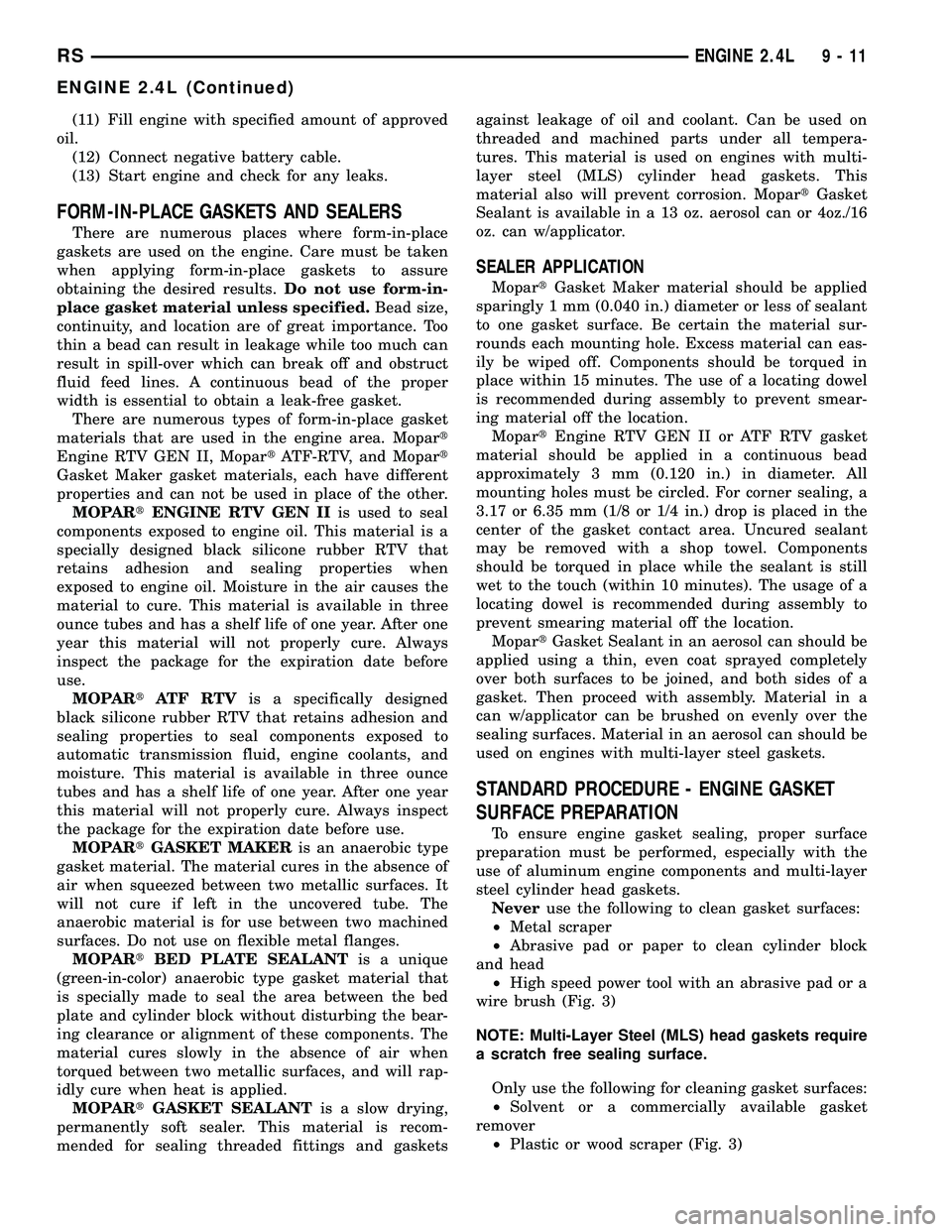
wire brush (Fig. 3)
NOTE: Multi-Layer Steel (MLS) head gaskets require
a scratch free sealing surface.
Only use the following for cleaning gasket surfaces:
²Solvent or a commercially available gasket
remover
²Plastic or wood scraper (Fig. 3)
RSENGINE 2.4L9-11
ENGINE 2.4L (Continued)
Page 1201 of 2339
AIR CLEANER ELEMENT
REMOVAL
(1) Unsnap 2 clips.
(2) Lift cover and pull toward the engine and
remove cover tabs from air box.
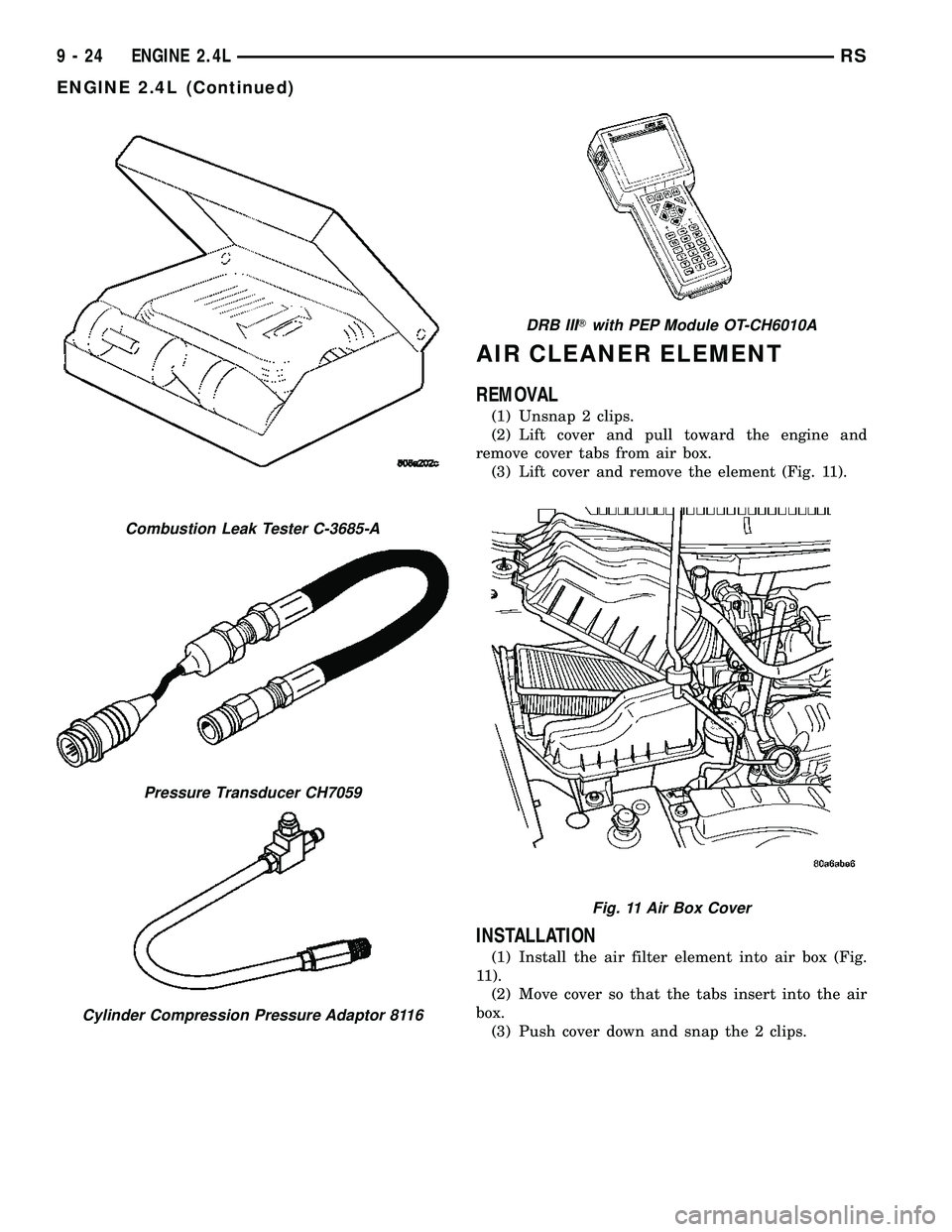
(3) Lift cover and remove the element (Fig. 11).
INSTALLATION
(1) Install the air filter element into air box (Fig.
11).
(2) Move cover so that the tabs insert into the air
box.
(3) Push cover down and snap the 2 clips.
Combustion Leak Tester C-3685-A
Pressure Transducer CH7059
Cylinder Compression Pressure Adaptor 8116
DRB IIITwith PEP Module OT-CH6010A
Fig. 11 Air Box Cover
9 - 24 ENGINE 2.4LRS
ENGINE 2.4L (Continued)
Page 1216 of 2339
thrust faces of No. 3 main bearing. DO NOT nick
crank pin or bearing fillets. After grinding, remove
rough edges from crankshaft oil holes and clean out
all passages.
CAUTION: With the nodular cast iron crankshafts, it
is important that the final paper or cloth polish be
in the same direction as normal rotation in the
engine.
INSTALLATION - CRANKSHAFT
CRANKSHAFT MAIN BEARING LOCATION
The crankshaft is supported in five main bearings.
All upper bearing shells in the crankcase have oil
grooves and holes. All lower bearing shellsexcept
for the thrust bearing half have oil grooves and holes
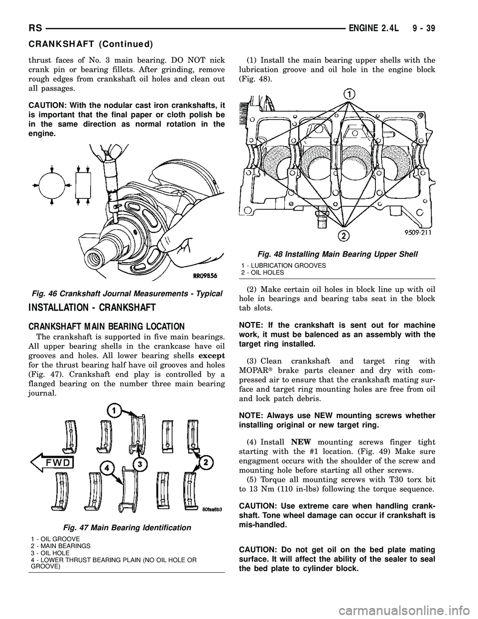
(Fig. 47). Crankshaft end play is controlled by a
flanged bearing on the number three main bearing
journal.(1) Install the main bearing upper shells with the
lubrication groove and oil hole in the engine block
(Fig. 48).
(2) Make certain oil holes in block line up with oil
hole in bearings and bearing tabs seat in the block
tab slots.
NOTE: If the crankshaft is sent out for machine
work, it must be balenced as an assembly with the
target ring installed.
(3) Clean crankshaft and target ring with
MOPARtbrake parts cleaner and dry with com-
pressed air to ensure that the crankshaft mating sur-
face and target ring mounting holes are free from oil
and lock patch debris.
NOTE: Always use NEW mounting screws whether
installing original or new target ring.
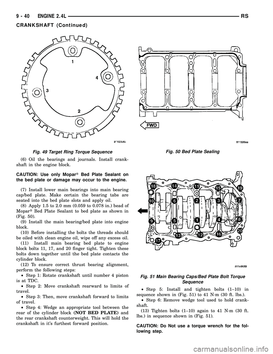
(4) InstallNEWmounting screws finger tight
starting with the #1 location. (Fig. 49) Make sure
engagment occurs with the shoulder of the screw and
mounting hole before starting all other screws.
(5) Torque all mounting screws with T30 torx bit
to 13 Nm (110 in-lbs) following the torque sequence.
CAUTION: Use extreme care when handling crank-
shaft. Tone wheel damage can occur if crankshaft is
mis-handled.
CAUTION: Do not get oil on the bed plate mating
surface. It will affect the ability of the sealer to seal
the bed plate to cylinder block.
Fig. 46 Crankshaft Journal Measurements - Typical
Fig. 47 Main Bearing Identification
1 - OIL GROOVE
2 - MAIN BEARINGS
3 - OIL HOLE
4 - LOWER THRUST BEARING PLAIN (NO OIL HOLE OR
GROOVE)
Fig. 48 Installing Main Bearing Upper Shell
1 - LUBRICATION GROOVES
2 - OIL HOLES
RSENGINE 2.4L9-39
CRANKSHAFT (Continued)
Page 1217 of 2339
(6) Oil the bearings and journals. Install crank-
shaft in the engine block.
CAUTION: Use only MoparTBed Plate Sealant on
the bed plate or damage may occur to the engine.
(7) Install lower main bearings into main bearing
cap/bed plate. Make certain the bearing tabs are
seated into the bed plate slots and apply oil.
(8) Apply 1.5 to 2.0 mm (0.059 to 0.078 in.) bead of
MopartBed Plate Sealant to bed plate as shown in
(Fig. 50).
(9) Install the main bearing/bed plate into engine
block.
(10) Before installing the bolts the threads should
be oiled with clean engine oil, wipe off any excess oil.
(11) Install main bearing bed plate to engine
block bolts 11, 17, and 20 finger tight. Tighten these
bolts down together until the bed plate contacts the
cylinder block.
(12) To ensure correct thrust bearing alignment,
perform the following steps:
²Step 1: Rotate crankshaft until number 4 piston
is at TDC.
²Step 2: Move crankshaft rearward to limits of
travel.
²Step 3: Then, move crankshaft forward to limits
of travel.
²Step 4: Wedge an appropriate tool between the
rear of the cylinder block(NOT BED PLATE)and
the rear crankshaft counterweight. This will hold the
crankshaft in it's furthest forward position.²Step 5: Install and tighten bolts (1±10) in
sequence shown in (Fig. 51) to 41 N´m (30 ft. lbs.).
²Step 6: Remove wedge tool used to hold crank-
shaft.
(13) Tighten bolts (1±10) again to 41 N´m (30 ft.
lbs.) in sequence shown in (Fig. 51).
CAUTION: Do Not use a torque wrench for the fol-
lowing step.
Fig. 49 Target Ring Torque SequenceFig. 50 Bed Plate Sealing
Fig. 51 Main Bearing Caps/Bed Plate Bolt Torque
Sequence
9 - 40 ENGINE 2.4LRS
CRANKSHAFT (Continued)
Page 1263 of 2339
Calibrate the tester according to the manufactur-
er's instructions. The shop air source for testing
should maintain 483 kPa (70 psi) minimum, 1,379
kPa (200 psi) maximum, with 552 kPa (80 psi) rec-
ommended.
Perform the test procedures on each cylinder
according to the tester manufacturer's instructions.
While testing, listen for pressurized air escaping
through the throttle body, tailpipe and oil filler cap
opening. Check for bubbles in the coolant.
All gauge pressure indications should be equal,
with no more than 25% leakage per cylinder.
FOR EXAMPLE:At 552 kPa (80 psi) input pres-
sure, a minimum of 414 kPa (60 psi) should be main-
tained in the cylinder.
STANDARD PROCEDURE
STANDARD PROCEDURE - MEASURING
BEARING CLEARANCE USING PLASTIGAGE
Engine crankshaft bearing clearances can be deter-
mined by use of Plastigage or equivalent. The follow-
ing is the recommended procedure for the use of
Plastigage:
(1) Remove oil film from surface to be checked.
Plastigage is soluble in oil.
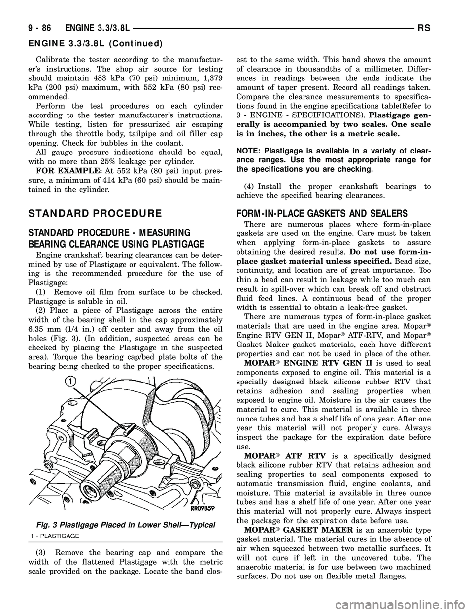
(2) Place a piece of Plastigage across the entire
width of the bearing shell in the cap approximately
6.35 mm (1/4 in.) off center and away from the oil
holes (Fig. 3). (In addition, suspected areas can be
checked by placing the Plastigage in the suspected
area). Torque the bearing cap/bed plate bolts of the
bearing being checked to the proper specifications.
(3) Remove the bearing cap and compare the
width of the flattened Plastigage with the metric
scale provided on the package. Locate the band clos-est to the same width. This band shows the amount
of clearance in thousandths of a millimeter. Differ-
ences in readings between the ends indicate the
amount of taper present. Record all readings taken.
Compare the clearance measurements to specsifica-
tions found in the engine specifications table(Refer to
9 - ENGINE - SPECIFICATIONS).Plastigage gen-
erally is accompanied by two scales. One scale
is in inches, the other is a metric scale.
NOTE: Plastigage is available in a variety of clear-
ance ranges. Use the most appropriate range for
the specifications you are checking.
(4) Install the proper crankshaft bearings to
achieve the specified bearing clearances.
FORM-IN-PLACE GASKETS AND SEALERS
There are numerous places where form-in-place
gaskets are used on the engine. Care must be taken
when applying form-in-place gaskets to assure
obtaining the desired results.Do not use form-in-
place gasket material unless specified.Bead size,
continuity, and location are of great importance. Too
thin a bead can result in leakage while too much can
result in spill-over which can break off and obstruct
fluid feed lines. A continuous bead of the proper
width is essential to obtain a leak-free gasket.
There are numerous types of form-in-place gasket
materials that are used in the engine area. Mopart
Engine RTV GEN II, MopartATF-RTV, and Mopart
Gasket Maker gasket materials, each have different
properties and can not be used in place of the other.
MOPARtENGINE RTV GEN IIis used to seal
components exposed to engine oil. This material is a
specially designed black silicone rubber RTV that
retains adhesion and sealing properties when
exposed to engine oil. Moisture in the air causes the
material to cure. This material is available in three
ounce tubes and has a shelf life of one year. After one
year this material will not properly cure. Always
inspect the package for the expiration date before
use.
MOPARtATF RTVis a specifically designed
black silicone rubber RTV that retains adhesion and
sealing properties to seal components exposed to
automatic transmission fluid, engine coolants, and
moisture. This material is available in three ounce
tubes and has a shelf life of one year. After one year
this material will not properly cure. Always inspect
the package for the expiration date before use.
MOPARtGASKET MAKERis an anaerobic type
gasket material. The material cures in the absence of
air when squeezed between two metallic surfaces. It
will not cure if left in the uncovered tube. The
anaerobic material is for use between two machined
surfaces. Do not use on flexible metal flanges.
Fig. 3 Plastigage Placed in Lower ShellÐTypical
1 - PLASTIGAGE
9 - 86 ENGINE 3.3/3.8LRS
ENGINE 3.3/3.8L (Continued)
Page 1264 of 2339
MOPARtBED PLATE SEALANTis a unique
(green-in-color) anaerobic type gasket material that
is specially made to seal the area between the bed
plate and cylinder block without disturbing the bear-
ing clearance or alignment of these components. The
material cures slowly in the absence of air when
torqued between two metallic surfaces, and will rap-
idly cure when heat is applied.
MOPARtGASKET SEALANTis a slow drying,
permanently soft sealer. This material is recom-
mended for sealing threaded fittings and gaskets
against leakage of oil and coolant. Can be used on
threaded and machined parts under all tempera-
tures. This material is used on engines with multi-
layer steel (MLS) cylinder head gaskets. This
material also will prevent corrosion. MopartGasket
Sealant is available in a 13 oz. aerosol can or 4oz./16
oz. can w/applicator.
SEALER APPLICATION
MopartGasket Maker material should be applied
sparingly 1 mm (0.040 in.) diameter or less of sealant
to one gasket surface. Be certain the material sur-
rounds each mounting hole. Excess material can eas-
ily be wiped off. Components should be torqued in
place within 15 minutes. The use of a locating dowel
is recommended during assembly to prevent smear-
ing material off the location.
MopartEngine RTV GEN II or ATF RTV gasket
material should be applied in a continuous bead
approximately 3 mm (0.120 in.) in diameter. All
mounting holes must be circled. For corner sealing, a
3.17 or 6.35 mm (1/8 or 1/4 in.) drop is placed in the
center of the gasket contact area. Uncured sealant
may be removed with a shop towel. Components
should be torqued in place while the sealant is still
wet to the touch (within 10 minutes). The usage of a
locating dowel is recommended during assembly to
prevent smearing material off the location.
MopartGasket Sealant in an aerosol can should be
applied using a thin, even coat sprayed completely
over both surfaces to be joined, and both sides of a
gasket. Then proceed with assembly. Material in a
can w/applicator can be brushed on evenly over the
sealing surfaces. Material in an aerosol can should be
used on engines with multi-layer steel gaskets.
STANDARD PROCEDURE - ENGINE GASKET
SURFACE PREPARATION
To ensure engine gasket sealing, proper surface
preparation must be performed, especially with the
use of aluminum engine components and multi-layer
steel cylinder head gaskets.
Neveruse the following to clean gasket surfaces:
²Metal scraper²Abrasive pad or paper to clean cylinder block
and head
²High speed power tool with an abrasive pad or a
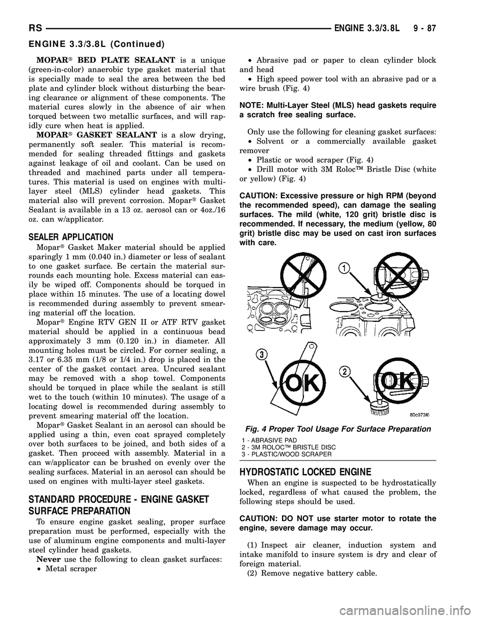
wire brush (Fig. 4)
NOTE: Multi-Layer Steel (MLS) head gaskets require
a scratch free sealing surface.
Only use the following for cleaning gasket surfaces:
²Solvent or a commercially available gasket
remover
²Plastic or wood scraper (Fig. 4)
²Drill motor with 3M RolocŸ Bristle Disc (white
or yellow) (Fig. 4)
CAUTION: Excessive pressure or high RPM (beyond
the recommended speed), can damage the sealing
surfaces. The mild (white, 120 grit) bristle disc is
recommended. If necessary, the medium (yellow, 80
grit) bristle disc may be used on cast iron surfaces
with care.
HYDROSTATIC LOCKED ENGINE
When an engine is suspected to be hydrostatically
locked, regardless of what caused the problem, the
following steps should be used.
CAUTION: DO NOT use starter motor to rotate the
engine, severe damage may occur.
(1) Inspect air cleaner, induction system and
intake manifold to insure system is dry and clear of
foreign material.
(2) Remove negative battery cable.
Fig. 4 Proper Tool Usage For Surface Preparation
1 - ABRASIVE PAD
2 - 3M ROLOCŸ BRISTLE DISC
3 - PLASTIC/WOOD SCRAPER
RSENGINE 3.3/3.8L9-87
ENGINE 3.3/3.8L (Continued)
Page 1278 of 2339
AIR CLEANER ELEMENT
REMOVAL
(1) Unsnap 2 clips.
(2) Lift cover and pull toward the engine and
remove cover tabs from air box.
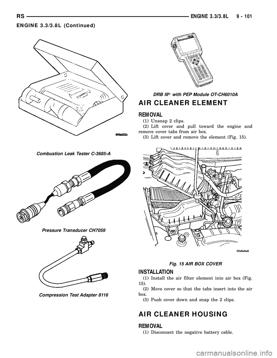
(3) Lift cover and remove the element (Fig. 15).
INSTALLATION
(1) Install the air filter element into air box (Fig.
15).
(2) Move cover so that the tabs insert into the air
box.
(3) Push cover down and snap the 2 clips.
AIR CLEANER HOUSING
REMOVAL
(1) Disconnect the negative battery cable.
Combustion Leak Tester C-3685-A
Pressure Transducer CH7059
Compression Test Adapter 8116
DRB IIITwith PEP Module OT-CH6010A
Fig. 15 AIR BOX COVER
RSENGINE 3.3/3.8L9 - 101
ENGINE 3.3/3.8L (Continued)