2005 CHRYSLER CARAVAN relay
[x] Cancel search: relayPage 1262 of 2339
(3) Remove torque converter or clutch housing
cover and inspect rear of block for evidence of oil.
Use a black light to check for the oil leak. If a leak is
present in this area, remove transmission for further
inspection.
(a) Circular spray pattern generally indicates
seal leakage or crankshaft damage.
(b) Where leakage tends to run straight down,
possible causes are a porous block, oil gallery cup
plug, bedplate to cylinder block mating surfaces
and seal bore. See proper repair procedures for
these items.
(4) If no leaks are detected, pressurize the crank-
case as previously described.
CAUTION: Do not exceed 20.6 kPa (3 psi).
(5) If the leak is not detected, very slowly turn the
crankshaft and watch for leakage. If a leak is
detected between the crankshaft and seal while
slowly turning the crankshaft, it is possible the
crankshaft seal surface is damaged. The seal area on
the crankshaft could have minor nicks or scratches
that can be polished out with emery cloth.
CAUTION: Use extreme caution when crankshaft
polishing is necessary to remove minor nicks and
scratches. The crankshaft seal flange is especially
machined to complement the function of the rear oil
seal.
(6) For bubbles that remain steady with shaft
rotation, no further inspection can be done until dis-
assembled.
(7) After the oil leak root cause and appropriate
corrective action have been identified, replace compo-
nent(s) as necessary.
DIAGNOSIS AND TESTING - CYLINDER
COMPRESSION PRESSURE TEST
The results of a cylinder compression pressure test
can be utilized to diagnose several engine malfunc-
tions.
Ensure the battery is completely charged and the
engine starter motor is in good operating condition.
Otherwise the indicated compression pressures may
not be valid for diagnosis purposes.
(1) Check engine oil level and add oil if necessary.
(2) Drive the vehicle until engine reaches normal
operating temperature. Select a route free from traf-
fic and other forms of congestion, observe all traffic
laws, and accelerate through the gears several times
briskly.
(3) Remove all spark plugs from engine. As spark
plugs are being removed, check electrodes for abnor-
mal firing indicators fouled, hot, oily, etc. Record cyl-
inder number of spark plug for future reference.(4) Remove the Auto Shutdown (ASD) relay from
the PDC.
(5) Be sure throttle blade is fully open during the
compression check.
(6) Insert compression gauge adaptor Special Tool
8116 or the equivalent, into the #1 spark plug hole in
cylinder head. Connect the 0±500 psi (Blue) pressure
transducer (Special Tool CH7059) with cable adap-
tors to the DRBIIIt. For Special Tool identification,
(Refer to 9 - ENGINE - SPECIAL TOOLS).
(7) Crank engine until maximum pressure is
reached on gauge. Record this pressure as #1 cylin-
der pressure.
(8) Repeat the previous step for all remaining cyl-
inders.
(9) Compression should not be less than 689 kPa
(100 psi) and not vary more than 25 percent from cyl-
inder to cylinder.
(10) If one or more cylinders have abnormally low
compression pressures, repeat the compression test.
(11) If the same cylinder or cylinders repeat an
abnormally low reading on the second compression
test, it could indicate the existence of a problem in
the cylinder in question.The recommended com-
pression pressures are to be used only as a
guide to diagnosing engine problems. An engine
should not be disassembled to determine the
cause of low compression unless some malfunc-
tion is present.
DIAGNOSIS AND TESTING - CYLINDER
COMBUSTION PRESSURE LEAKAGE TEST
The combustion pressure leakage test provides an
accurate means for determining engine condition.
Combustion pressure leakage testing will detect:
²Exhaust and intake valve leaks (improper seat-
ing).
²Leaks between adjacent cylinders or into water
jacket.
²Any causes for combustion/compression pressure
loss.
WARNING: DO NOT REMOVE THE PRESSURE CAP
WITH THE SYSTEM HOT AND UNDER PRESSURE
BECAUSE SERIOUS BURNS FROM COOLANT CAN
OCCUR.
Check the coolant level and fill as required. DO
NOT install the pressure cap.
Start and operate the engine until it attains nor-
mal operating temperature, then turn the engine
OFF.
Clean spark plug recesses with compressed air.
Remove the spark plugs.
Remove the oil filler cap.
Remove the air cleaner.
RSENGINE 3.3/3.8L9-85
ENGINE 3.3/3.8L (Continued)
Page 1350 of 2339
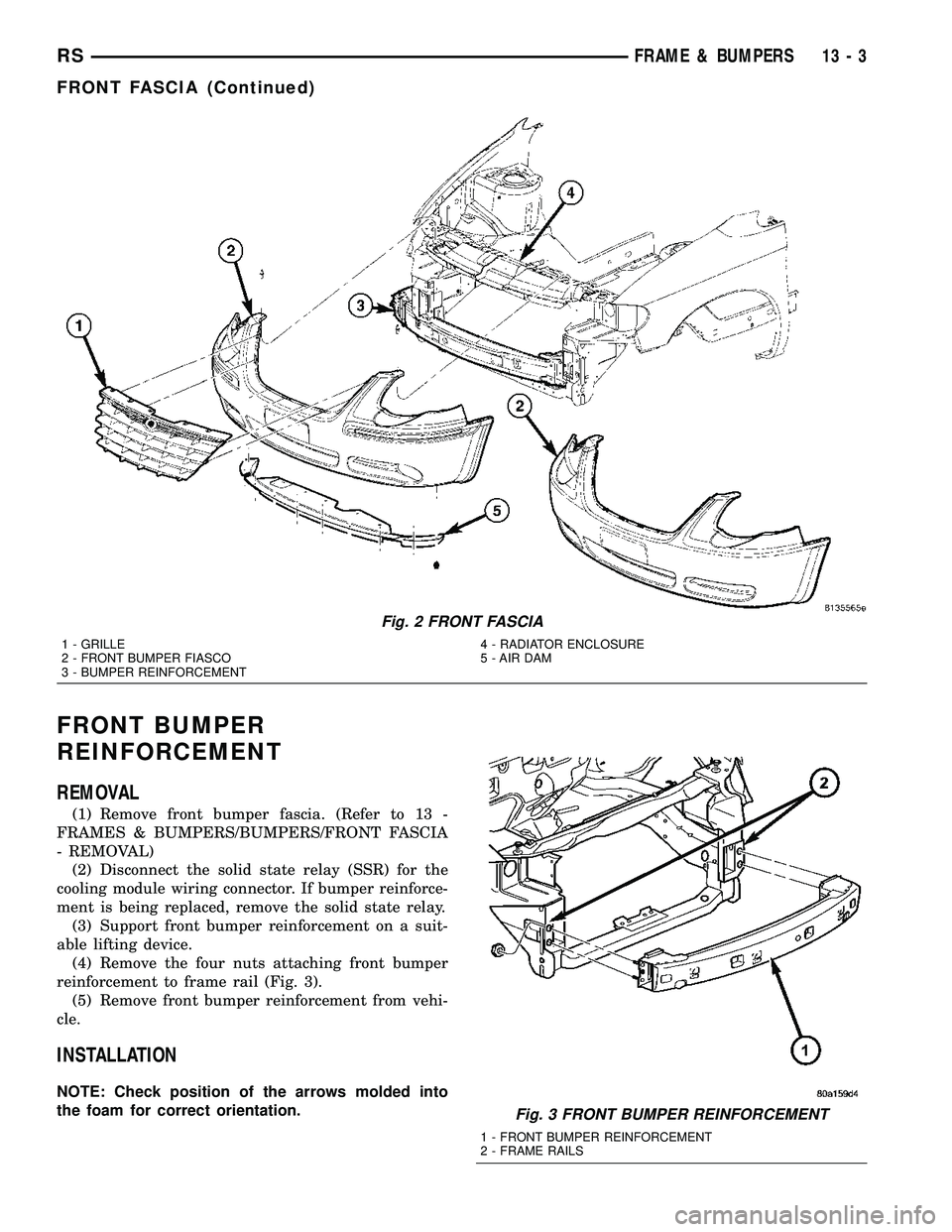
FRONT BUMPER
REINFORCEMENT
REMOVAL
(1) Remove front bumper fascia. (Refer to 13 -
FRAMES & BUMPERS/BUMPERS/FRONT FASCIA
- REMOVAL)
(2) Disconnect the solid state relay (SSR) for the
cooling module wiring connector. If bumper reinforce-
ment is being replaced, remove the solid state relay.
(3) Support front bumper reinforcement on a suit-
able lifting device.
(4) Remove the four nuts attaching front bumper
reinforcement to frame rail (Fig. 3).
(5) Remove front bumper reinforcement from vehi-
cle.
INSTALLATION
NOTE: Check position of the arrows molded into
the foam for correct orientation.
Fig. 2 FRONT FASCIA
1 - GRILLE
2 - FRONT BUMPER FIASCO
3 - BUMPER REINFORCEMENT4 - RADIATOR ENCLOSURE
5 - AIR DAM
Fig. 3 FRONT BUMPER REINFORCEMENT
1 - FRONT BUMPER REINFORCEMENT
2 - FRAME RAILS
RSFRAME & BUMPERS13-3
FRONT FASCIA (Continued)
Page 1351 of 2339
(1) Support front bumper reinforcement using a
suitable lifting device and lift into position.
(2) Install the four nuts attaching reinforcement to
frame rails. Tighten nuts to 54 N´m (40 ft. lbs.)
torque.
(3) Connect the solid state relay (SSR) wiring con-
nector. If bumper reinforcement was replaced, install
the solid state relay onto the bumper reinforcement.
(4) Install front fascia. (Refer to 13 - FRAMES &
BUMPERS/BUMPERS/FRONT FASCIA - INSTAL-
LATION).
REAR FASCIA
REMOVAL
(1) Open liftgate.
(2) Remove attaching screw from upper fascia to
the liftgate tower, right side and left side.
(3) Hoist and support vehicle with safety stands.
(4) Disconnect rear park assist wire connector, if
equipped.
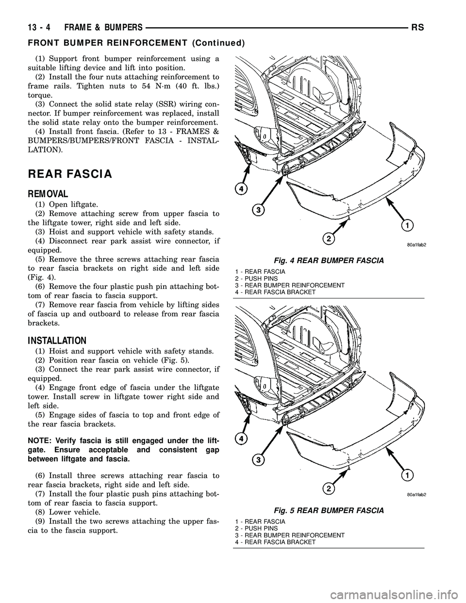
(5) Remove the three screws attaching rear fascia
to rear fascia brackets on right side and left side
(Fig. 4).
(6) Remove the four plastic push pin attaching bot-
tom of rear fascia to fascia support.
(7) Remove rear fascia from vehicle by lifting sides
of fascia up and outboard to release from rear fascia
brackets.
INSTALLATION
(1) Hoist and support vehicle with safety stands.
(2) Position rear fascia on vehicle (Fig. 5).
(3) Connect the rear park assist wire connector, if
equipped.
(4) Engage front edge of fascia under the liftgate
tower. Install screw in liftgate tower right side and
left side.
(5) Engage sides of fascia to top and front edge of
the rear fascia brackets.
NOTE: Verify fascia is still engaged under the lift-
gate. Ensure acceptable and consistent gap
between liftgate and fascia.
(6) Install three screws attaching rear fascia to
rear fascia brackets, right side and left side.
(7) Install the four plastic push pins attaching bot-
tom of rear fascia to fascia support.
(8) Lower vehicle.
(9) Install the two screws attaching the upper fas-
cia to the fascia support.
Fig. 4 REAR BUMPER FASCIA
1 - REAR FASCIA
2 - PUSH PINS
3 - REAR BUMPER REINFORCEMENT
4 - REAR FASCIA BRACKET
Fig. 5 REAR BUMPER FASCIA
1 - REAR FASCIA
2 - PUSH PINS
3 - REAR BUMPER REINFORCEMENT
4 - REAR FASCIA BRACKET
13 - 4 FRAME & BUMPERSRS
FRONT BUMPER REINFORCEMENT (Continued)
Page 1367 of 2339
FUEL DELIVERY
DESCRIPTION
DESCRIPTION
The front wheel drive car uses a plastic fuel tank
located rear center of the vehicle.
The Fuel Delivery System consists of: the following
items:
²Electric fuel pump module
²Fuel filter
²Tubes/lines/hoses
²Fuel injectors
The in-tank fuel pump module contains the fuel
pump. The pump is serviced as part of the fuel pump
module. Refer to Fuel Pump Module.
The fuel filter is replaceable only as part of the
fuel pump module.
DESCRIPTION - FFV REPLACEMENT PARTS
Many components in a Flexible Fuel Vehicle (FFV)
are designed to be compatible with ethanol. Always
be sure that the vehicle is serviced with correct etha-
nol compatible parts.
CAUTION: Replacing fuel system components with
non-ethanol compatible components can damage
your vehicle and may void the warranty.
OPERATION
The fuel system provides fuel pressure by an
in-tank pump module. The Powertrain Control Mod-
ule (PCM) controls the operation of the fuel system
by providing battery voltage to the fuel pump
through the fuel pump relay. The PCM requires only
three inputs and a good ground to operate the fuel
pump relay. The three inputs are:
²Ignition voltage
²Crankshaft Position (CKP) sensor
²Camshaft Position (CMP) sensor
DIAGNOSIS AND TESTING - FUEL DELIVERY
SYSTEM
(Refer to Appropriate Diagnostic Information)
STANDARD PROCEDURE
STANDARD PROCEDURE - FUEL SYSTEM
PRESSURE RELEASE PROCEDURE
(1) Remove Fuel Pump relay from Power Distribu-
tion Center (PDC). For location of relay, refer to label
on underside of PDC cover.
(2) Start and run engine until it stalls.(3) Attempt restarting engine until it will no
longer run.
(4) Turn ignition key to OFF position.
(5) Return fuel pump relay to PDC.
(6) One or more Diagnostic Trouble Codes (DTC's)
may have been stored in PCM memory due to fuel
pump relay removal. The DRB IIItscan tool must be
used to erase a DTC.
STANDARD PROCEDURE - DRAINING FUEL
TANK
Two different procedures may be used to drain fuel
tank (lowering tank or using DRBIIItscan tool).
The quickest draining procedure involves lowering
the fuel tank.
WARNING: RELEASE FUEL SYSTEM PRESSURE
BEFORE SERVICING FUEL SYSTEM COMPONENTS.
SERVICE VEHICLES IN WELL VENTILATED AREAS
AND AVOID IGNITION SOURCES. NEVER SMOKE
WHILE SERVICING THE VEHICLE. THIS MAY
RESULT IN PERSONAL INJURY OR DEATH.
As an alternative procedure, the electric fuel pump
may be activated allowing tank to be drained at fuel
rail connection. Refer to DRBIIItscan tool for fuel
pump activation procedures. Before disconnecting
fuel line at fuel rail, release fuel pressure. Refer to
the Fuel System Pressure Release Procedure in this
group for procedures. Disconnect the fuel line at the
fuel rail and remove the plastic retainer from the
fuel rail. Take plastic retainer and install it back into
the fuel line from body. Check the O-ring and make
sure that it is in place and not damaged. Attach end
of special test hose tool number 6539 at fuel line con-
nection from the body line. Position opposite end of
this hose tool to an approved gasoline draining sta-
tion. Activate fuel pump and drain tank until empty.
When done remove the special test hose tool number
6539 from the body line. Remove the plastic retainer
from the special test hose tool number 6539 and rein-
stall it into the fuel line from the body. Check the
O-ring and make sure that it is in place and not
damaged. Install the fuel line to the fuel rail.
If electric fuel pump is not operating, tank must be
lowered for fuel draining. Refer to following proce-
dures.
(1) Remove fuel filler cap.
(2) Perform the Fuel System Pressure Release pro-
cedure.
(3) Disconnect negative cable from battery.
(4) Raise vehicle and support.
(5) Certain models are equipped with a separate
grounding wire (strap) connecting the fuel fill tube
assembly to the body. Disconnect wire by removing
screw.
14 - 2 FUEL DELIVERYRS
Page 1373 of 2339
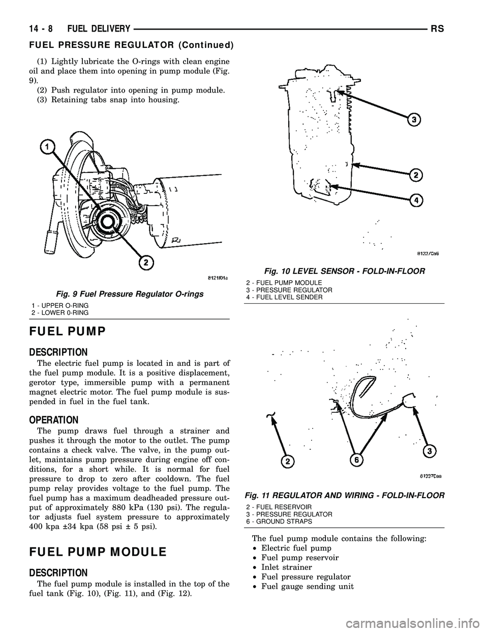
(1) Lightly lubricate the O-rings with clean engine
oil and place them into opening in pump module (Fig.
9).
(2) Push regulator into opening in pump module.
(3) Retaining tabs snap into housing.
FUEL PUMP
DESCRIPTION
The electric fuel pump is located in and is part of
the fuel pump module. It is a positive displacement,
gerotor type, immersible pump with a permanent
magnet electric motor. The fuel pump module is sus-
pended in fuel in the fuel tank.
OPERATION
The pump draws fuel through a strainer and
pushes it through the motor to the outlet. The pump
contains a check valve. The valve, in the pump out-
let, maintains pump pressure during engine off con-
ditions, for a short while. It is normal for fuel
pressure to drop to zero after cooldown. The fuel
pump relay provides voltage to the fuel pump. The
fuel pump has a maximum deadheaded pressure out-
put of approximately 880 kPa (130 psi). The regula-
tor adjusts fuel system pressure to approximately
400 kpa 34 kpa (58 psi 5 psi).
FUEL PUMP MODULE
DESCRIPTION
The fuel pump module is installed in the top of the
fuel tank (Fig. 10), (Fig. 11), and (Fig. 12).The fuel pump module contains the following:
²Electric fuel pump
²Fuel pump reservoir
²Inlet strainer
²Fuel pressure regulator
²Fuel gauge sending unit
Fig. 9 Fuel Pressure Regulator O-rings
1 - UPPER O-RING
2 - LOWER 0-RING
Fig. 10 LEVEL SENSOR - FOLD-IN-FLOOR
2 - FUEL PUMP MODULE
3 - PRESSURE REGULATOR
4 - FUEL LEVEL SENDER
Fig. 11 REGULATOR AND WIRING - FOLD-IN-FLOOR
2 - FUEL RESERVOIR
3 - PRESSURE REGULATOR
6 - GROUND STRAPS
14 - 8 FUEL DELIVERYRS
FUEL PRESSURE REGULATOR (Continued)
Page 1374 of 2339
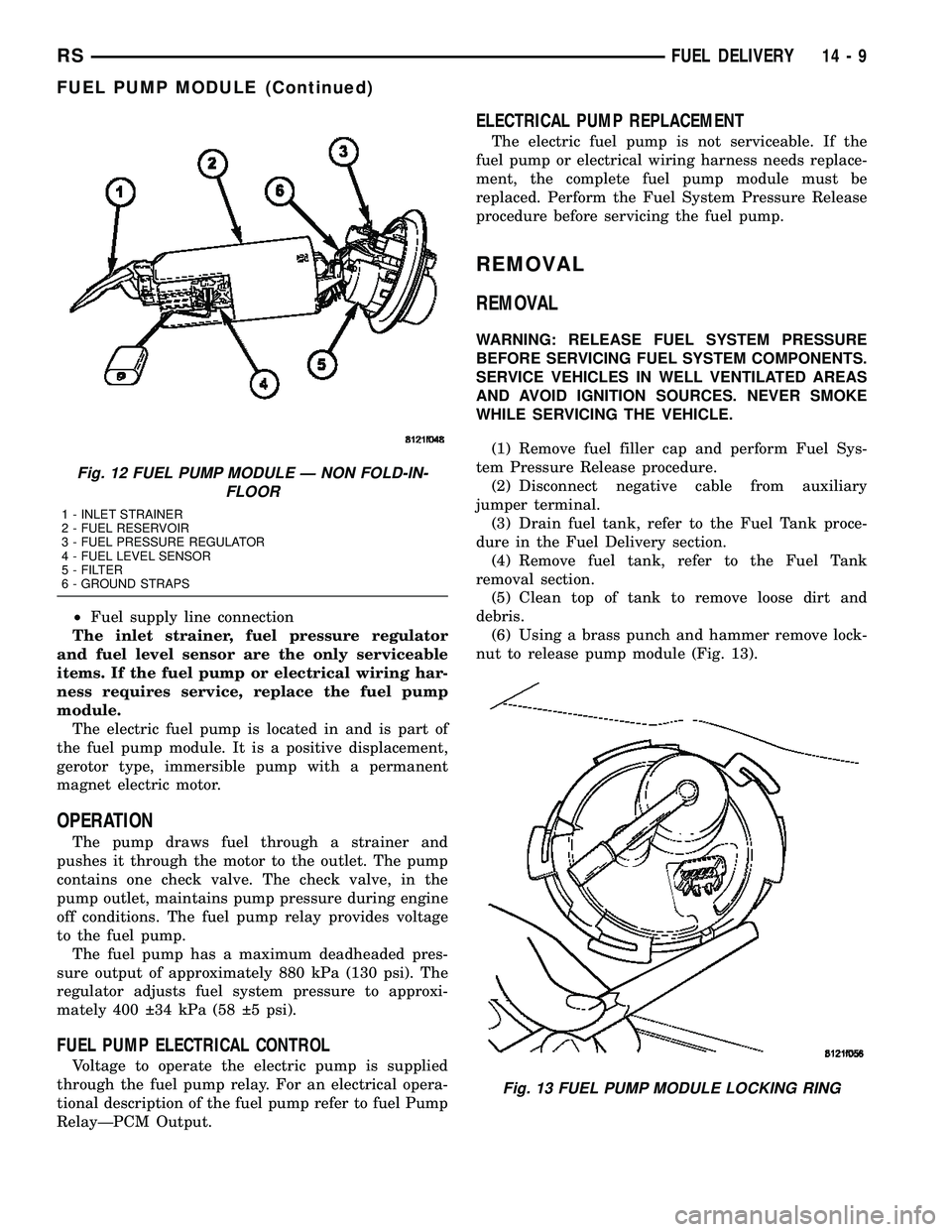
²Fuel supply line connection
The inlet strainer, fuel pressure regulator
and fuel level sensor are the only serviceable
items. If the fuel pump or electrical wiring har-
ness requires service, replace the fuel pump
module.
The electric fuel pump is located in and is part of
the fuel pump module. It is a positive displacement,
gerotor type, immersible pump with a permanent
magnet electric motor.
OPERATION
The pump draws fuel through a strainer and
pushes it through the motor to the outlet. The pump
contains one check valve. The check valve, in the
pump outlet, maintains pump pressure during engine
off conditions. The fuel pump relay provides voltage
to the fuel pump.
The fuel pump has a maximum deadheaded pres-
sure output of approximately 880 kPa (130 psi). The
regulator adjusts fuel system pressure to approxi-
mately 400 34 kPa (58 5 psi).
FUEL PUMP ELECTRICAL CONTROL
Voltage to operate the electric pump is supplied
through the fuel pump relay. For an electrical opera-
tional description of the fuel pump refer to fuel Pump
RelayÐPCM Output.
ELECTRICAL PUMP REPLACEMENT
The electric fuel pump is not serviceable. If the
fuel pump or electrical wiring harness needs replace-
ment, the complete fuel pump module must be
replaced. Perform the Fuel System Pressure Release
procedure before servicing the fuel pump.
REMOVAL
REMOVAL
WARNING: RELEASE FUEL SYSTEM PRESSURE
BEFORE SERVICING FUEL SYSTEM COMPONENTS.
SERVICE VEHICLES IN WELL VENTILATED AREAS
AND AVOID IGNITION SOURCES. NEVER SMOKE
WHILE SERVICING THE VEHICLE.
(1) Remove fuel filler cap and perform Fuel Sys-
tem Pressure Release procedure.
(2) Disconnect negative cable from auxiliary
jumper terminal.
(3) Drain fuel tank, refer to the Fuel Tank proce-
dure in the Fuel Delivery section.
(4) Remove fuel tank, refer to the Fuel Tank
removal section.
(5) Clean top of tank to remove loose dirt and
debris.
(6) Using a brass punch and hammer remove lock-
nut to release pump module (Fig. 13).
Fig. 12 FUEL PUMP MODULE Ð NON FOLD-IN-
FLOOR
1 - INLET STRAINER
2 - FUEL RESERVOIR
3 - FUEL PRESSURE REGULATOR
4 - FUEL LEVEL SENSOR
5 - FILTER
6 - GROUND STRAPS
Fig. 13 FUEL PUMP MODULE LOCKING RING
RSFUEL DELIVERY14-9
FUEL PUMP MODULE (Continued)
Page 1383 of 2339
QUICK CONNECT FITTING
STANDARD PROCEDURE - QUICK-CONNECT
FITTINGS
REMOVAL
When disconnecting a quick-connect fitting, the
retainer will remain on the fuel tube nipple.
WARNING: RELEASE FUEL SYSTEM PRESSURE
BEFORE DISCONNECTING A QUICK-CONNECT FIT-
TINGS. REFER TO THE FUEL PRESSURE RELEASE
PROCEDURE. THIS MAY RESULT IN PERSONAL
INJURY OR DEATH.
(1) Perform Fuel Pressure Release Procedure.
Refer to the Fuel Pressure Release Procedure in this
section.
(2) Disconnect negative cable from battery or aux-
iliary jumper terminal.
(3) Squeeze retainer tabs together and pull fuel
tube/quick-connect fitting assembly off of fuel tube
nipple. The retainer will remain on fuel tube.
INSTALLATION
CAUTION: Make sure that the o-ring in installed in
fitting. Never install a quick-connect fitting without
the retainer being either on the fuel tube or already
in the quick-connect fitting. In either case, ensure
the retainer locks securely into the quick-connect
fitting by firmly push-pulling-push on fuel tube and
fitting to ensure it is secured.
(1) Using a clean lint free cloth, clean the fuel tube
nipple and retainer.
(2) Prior to connecting the fitting to the fuel tube,
coat the fuel tube nipple with clean engine oil.
(3) Push the quick-connect fitting over the fuel
tube until theretainer seats and a click is heard.
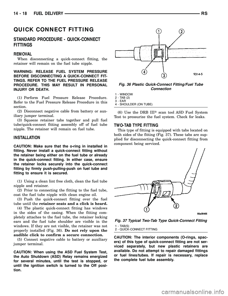
(4) The plastic quick-connect fitting has windows
in the sides of the casing. When the fitting com-
pletely attaches to the fuel tube, the retainer locking
ears and the fuel tube shoulder are visible in the
windows. If they are not visible, the retainer was not
properly installed (Fig. 36).Do not rely upon the
audible click to confirm a secure connection.
(5) Connect negative cable to battery or auxiliary
jumper terminal.
CAUTION: When using the ASD Fuel System Test,
the Auto Shutdown (ASD) Relay remains energized
for several minutes, until the test is stopped, or
until the ignition switch is turned to the Off posi-
tion.(6) Use the DRB IIItscan tool ASD Fuel System
Test to pressurize the fuel system. Check for leaks.
TWO-TAB TYPE FITTING
This type of fitting is equipped with tabs located on
both sides of the fitting (Fig. 37). These tabs are sup-
plied for disconnecting the quick-connect fitting from
component being serviced.
CAUTION: The interior components (O-rings, spac-
ers) of this type of quick-connect fitting are not ser-
viced separately, but new plastic retainers are
available. Do not attempt to repair damaged fittings
or fuel lines/tubes. If repair is necessary, replace
the complete fuel tube assembly.
Fig. 36 Plastic Quick-Connect Fitting/Fuel Tube
Connection
1 - WINDOW
2-TAB(2)
3 - EAR
4 - SHOULDER (ON TUBE)
Fig. 37 Typical Two-Tab Type Quick-Connect Fitting
1 - TAB(S)
2 - QUICK-CONNECT FITTING
14 - 18 FUEL DELIVERYRS
Page 1386 of 2339
FUEL INJECTION
TABLE OF CONTENTS
page page
FUEL INJECTION
OPERATION
OPERATION - INJECTION SYSTEM.......22
OPERATION - MODES OF OPERATION....22
FUEL CORRECTION or ADAPTIVE
MEMORIES..........................24
PROGRAMMABLE COMMUNICATIONS
INTERFACE (PCI) BUS.................25
SYSTEM DIAGNOSIS..................26
SPECIFICATIONS
TORQUE............................26
SPECIAL TOOLS
FUEL...............................27
ACCELERATOR PEDAL
REMOVAL.............................28
INSTALLATION.........................28
CRANKSHAFT POSITION SENSOR
DESCRIPTION.........................29
OPERATION...........................29
REMOVAL.............................30
INSTALLATION - 2.4L....................30
ENGINE SPEED SENSOR
DESCRIPTION.........................30
OPERATION...........................30
FUEL INJECTOR
DESCRIPTION.........................30
OPERATION...........................31
REMOVAL
REMOVAL - 2.4L......................31
REMOVAL - 3.3/3.8L...................31
INSTALLATION
INSTALLATION - 2.4L..................32
INSTALLATION - 3.3/3.8L................32
FUEL PUMP RELAY
DESCRIPTION.........................32
OPERATION...........................32
IDLE AIR CONTROL MOTOR
DESCRIPTION.........................33
OPERATION...........................33REMOVAL.............................33
INSTALLATION.........................33
INLET AIR TEMPERATURE SENSOR
DESCRIPTION.........................34
MAP SENSOR
DESCRIPTION.........................34
OPERATION...........................34
REMOVAL
REMOVAL - 2.4L......................35
REMOVAL - 3.3/3.8L...................35
INSTALLATION
INSTALLATION - 2.4L..................36
INSTALLATION - 3.3/3.8L................36
O2 SENSOR
DESCRIPTION.........................36
OPERATION...........................36
REMOVAL
REMOVAL - UPSTREAM 1/1 - 2.4L........37
REMOVAL - UPSTREAM 1/1 - 3.3/3.8L.....38
REMOVAL - DOWNSTREAM 1/2 - 2.4/3.3/
3.8L................................38
INSTALLATION
INSTALLATION - UPSTREAM 1/1 - 2.4L.....38
INSTALLATION - UPSTREAM 1/1 - 3.3/3.8L . . 39
INSTALLATION DOWNSTREAM 2/1 -
2.4/3.3/3.8L..........................39
THROTTLE BODY
DESCRIPTION.........................39
OPERATION...........................39
REMOVAL.............................40
INSTALLATION.........................40
THROTTLE CONTROL CABLE
REMOVAL.............................40
INSTALLATION.........................40
THROTTLE POSITION SENSOR
DESCRIPTION.........................40
OPERATION...........................41
REMOVAL - 3.3/3.8L.....................41
INSTALLATION - 3.3/3.8L.................41
RSFUEL INJECTION14-21