Page 65 of 86

PERIODIC MAINTENANCE AND MINOR REPAIR
6-28
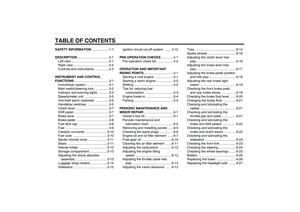
6 3. Remove the headlight bulb holder
by turning it counterclockwise, and
then remove the defective bulb.
WARNING
EWA10790
Headlight bulbs get very hot. There-
fore, keep flammable products away
from a lit headlight bulb, and do not
touch the bulb until it has cooleddown.
4. Place a new headlight bulb into po-
sition, and then secure it with the
bulb holder.CAUTION:
ECA10660
Do not touch the glass part of the
headlight bulb to keep it free from
oil, otherwise the transparency of
the glass, the luminosity of the bulb,
and the bulb life will be adversely af-
fected. Thoroughly clean off any dirt
and fingerprints on the headlight
bulb using a cloth moistened with al-cohol or thinner.5. Install the headlight bulb cover,
and then connect the coupler.
6. Install the headlight unit by install-
ing the screws.
7. Have a Yamaha dealer adjust the
headlight beam if necessary.
1. Headlight coupler
2. Headlight bulb cover
1. Headlight bulb holder
1. Do not touch the glass part of the bulb.
U5SCE1E0.book Page 28 Monday, September 8, 2003 11:32 AM
Page 66 of 86
PERIODIC MAINTENANCE AND MINOR REPAIR
6-29
6
EAU24281
Replacing a turn signal light
bulb or the tail/brake light bulb 1. Remove the lens by removing the
screws.2. Remove the defective bulb by
pushing it in and turning it counter-
clockwise.
3. Insert a new bulb into the socket,
push it in, and then turn it clock-
wise until it stops.
4. Install the lens by installing the
screws.
CAUTION:
ECA10680
Do not overtighten the screws, oth-erwise the lens may break.
EAU33411
Replacing the auxiliary light
bulb If the auxiliary light bulb burns out, re-
place it as follows.
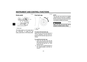
1. Remove the headlight unit by re-
moving the screws.
2. Remove the socket (together with
the bulb) by pushing it in and turn-
ing it counterclockwise.
1. Screw
1. Screw
1. Screw
U5SCE1E0.book Page 29 Monday, September 8, 2003 11:32 AM
Page 67 of 86

PERIODIC MAINTENANCE AND MINOR REPAIR
6-30
6 3. Remove the defective bulb by
pushing it in and turning it counter-
clockwise.
4. Insert a new bulb into the socket,
push it in, and then turn it clock-
wise until it stops.
5. Install the socket (together with the
bulb) by pushing it in and turning it
clockwise until it stops.
6. Install the headlight unit by install-
ing the screws.
EAU24350
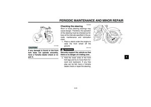
Supporting the motorcycle Since this model is not equipped with a
centerstand, follow these precautions
when removing the front and rear
wheel or performing other maintenance
requiring the motorcycle to stand up-
right. Check that the motorcycle is in a
stable and level position before starting
any maintenance. A strong wooden
box can be placed under the engine for
added stability.
To service the front wheel
1. Stabilize the rear of the motorcycle
by using a motorcycle stand or, if
an additional motorcycle stand is
not available, by placing a jack un-
der the frame in front of the rear
wheel.
2. Raise the front wheel off the
ground by using a motorcycle
stand.
To service the rear wheel
Raise the rear wheel off the ground by
using a motorcycle stand or, if a motor-
cycle stand is not available, by placinga jack either under each side of the
frame in front of the rear wheel or under
each side of the swingarm.
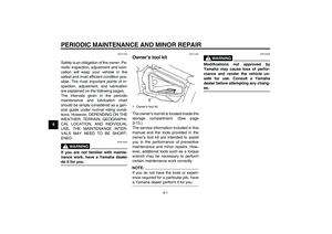
1. Auxiliary light bulb socket
U5SCE1E0.book Page 30 Monday, September 8, 2003 11:32 AM
Page 68 of 86

PERIODIC MAINTENANCE AND MINOR REPAIR
6-31
6
EAU24360
Front wheel
EAU24660
To remove the front wheel
WARNING
EWA10820
�
It is advisable to have a Yamaha
dealer service the wheel.
�
Securely support the motor-
cycle so that there is no dangerof it falling over.
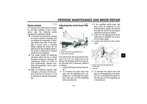
1. Disconnect the speedometer ca-
ble from the front wheel.
2. Loosen the front wheel axle pinch
bolt.
3. Remove the rubber cap, and then
loosen the wheel axle.4. Lift the front wheel off the ground
according to the procedure on
page 6-30.
5. Pull the wheel axle out, and then
remove the wheel.
CAUTION:
ECA11070
Do not apply the brake after the
wheel has been removed together
with the brake disc, otherwise thebrake pads will be forced shut.
EAU24921
To install the front wheel
1. Install the speedometer gear unit
into the wheel hub so that the pro-
jections mesh with the slots.
2. Lift the wheel up between the fork
legs.NOTE:Make sure that there is enough space
between the brake pads before insert-
ing the brake disc and that the slot in
the speedometer gear unit fits over theretainer on the fork leg.
3. Insert the wheel axle.
4. Lower the front wheel so that it is
on the ground.
1. Speedometer cable
1. Rubber cap
2. Wheel axle
3. Front wheel axle pinch bolt
1. Speedometer gear unit
2. Speedometer cable
3. Retainer
U5SCE1E0.book Page 31 Monday, September 8, 2003 11:32 AM
Page 69 of 86

PERIODIC MAINTENANCE AND MINOR REPAIR
6-32
6 5. Tighten the wheel axle and front
wheel axle pinch bolt to the speci-
fied torques, and then install the
rubber cap.
6. While applying the front brake,
push down hard on the handlebars
several times to check if the front
fork compresses and rebounds
smoothly.
7. Connect the speedometer cable.
EAU25080
Rear wheel
EAU25141
To remove the rear wheel
WARNING
EWA10820
�
It is advisable to have a Yamaha
dealer service the wheel.
�
Securely support the motor-
cycle so that there is no dangerof it falling over.
1. Loosen the axle nut.
2. Disconnect the brake torque rod
from the brake shoe plate by re-
moving the bolt and nut.
3. Loosen the brake torque rod nut at
the swingarm.4. Remove the brake pedal free play
adjusting nut, and then disconnect
the brake rod from the brake cam-
shaft lever.
5. Remove panel A. (See page 6-5.)
6. Remove the bolts that secure the
final gear case to the swingarm.
Tightening torques:
Wheel axle:
59 Nm (5.9 m·kgf, 43 ft·lbf)
Front wheel axle pinch bolt:
20 Nm (2.0 m·kgf, 14 ft·lbf)
1. Axle nut
1. Brake pedal free play adjusting nut
2. Brake camshaft lever
3. Bolt and nut (shoe plate)
4. Brake torque rod
5. Nut (swingarm)
6. Brake rod
U5SCE1E0.book Page 32 Monday, September 8, 2003 11:32 AM
Page 70 of 86

PERIODIC MAINTENANCE AND MINOR REPAIR
6-33
67. Lift the rear wheel off the ground
according to the procedure on
page 6-30.
8. While supporting the drive shaft,
pull the rear wheel back to remove
the following parts as an assem-
bly: wheel, wheel axle, final gear
case, and drive shaft.
NOTE:Make sure to support the drive shaft asit is being pulled out.
EAU25511
To install the rear wheel
1. Install the rear wheel, wheel axle,
final gear case, and drive shaft by
pushing the wheel forward and
guiding the drive shaft into the mid-
dle gear universal joint.
2. Install the final gear case bolts.
3. Install the brake rod onto the brake
camshaft lever, and then install the
brake pedal free play adjusting nut
onto the brake rod.
4. Install the brake torque rod bolt
and nut at the brake shoe plate.
5. Install the panel.
6. Lower the rear wheel so that it is
on the ground.7. Tighten the axle nut, the final gear
case bolts and the brake torque
rod nuts to the specified torques.
8. Adjust the brake pedal free play.
(See page 6-18.)
WARNING
EWA10660
After adjusting the brake pedal free
play, check the operation of thebrake light.
1. Bolt
2. Final gear case
1. Middle gear universal joint
2. Drive shaft
Tightening torques:
Axle nut:
92 Nm (9.2 m·kgf, 67 ft·lbf)
Final gear case bolt:
74 Nm (7.4 m·kgf, 54 ft·lbf)
Brake torque rod nut:
20 Nm (2.0 m·kgf, 14 ft·lbf)
U5SCE1E0.book Page 33 Monday, September 8, 2003 11:32 AM
Page 71 of 86
PERIODIC MAINTENANCE AND MINOR REPAIR
6-34
6
EAU25850
Troubleshooting Although Yamaha motorcycles receive
a thorough inspection before shipment
from the factory, trouble may occur dur-
ing operation. Any problem in the fuel,
compression, or ignition systems, for
example, can cause poor starting and
loss of power.
The following troubleshooting chart
represents a quick and easy procedure
for checking these vital systems your-
self. However, should your motorcycle
require any repair, take it to a Yamaha
dealer, whose skilled technicians have
the necessary tools, experience, and
know-how to service the motorcycle
properly.
Use only genuine Yamaha replace-
ment parts. Imitation parts may look like
Yamaha parts, but they are often inferi-
or, have a shorter service life and can
lead to expensive repair bills.
U5SCE1E0.book Page 34 Monday, September 8, 2003 11:32 AM
Page 72 of 86

PERIODIC MAINTENANCE AND MINOR REPAIR
6-35
6
EAU25891
Troubleshooting chart
WARNING
EWA10840
Keep away open flames and do not smoke while checking or working on the fuel system.
Check the fuel level in
the fuel tank.1. Fuel
There is enough fuel.
There is no fuel.
Check the compression.
Supply fuel.
The engine does not start.
Check the compression.
Operate the electric starter.2. Compression
There is compression.
There is no compression.
Check the ignition.
Have a Yamaha dealer
check the vehicle.
Remove the spark plugs
and check the electrodes.3. Ignition
Wipe off with a dry cloth and correct the
spark plug gaps, or replace the spark plugs.
Have a Yamaha dealer check the vehicle.
The engine does not start.
Have a Yamaha dealer
check the vehicle.
The engine does not start.
Check the battery.
Operate the electric starter.4. Battery
The engine turns over
quickly.
The engine turns over
slowly.
The battery is good.Check the battery lead connections,
and charge the battery if necessary.
DryWet
Open the throttle halfway and operate
the electric starter.
U5SCE1E0.book Page 35 Monday, September 8, 2003 11:32 AM