Page 25 of 86

INSTRUMENT AND CONTROL FUNCTIONS
3-11
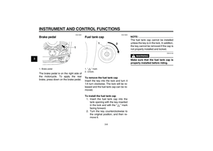
3 This indicates reserve. With the fuel
cock lever in this position, the fuel re-
serve is made available. Turn the fuel
cock lever to this position if you run out
of fuel while riding. When this occurs,
refuel as soon as possible and be sure
to turn the fuel cock lever back to “ON”!
EAU13620
Starter (choke) knob “” Starting a cold engine requires a richer
air-fuel mixture, which is supplied by
the starter (choke).
Move the knob in direction (a) to turn on
the starter (choke).
Move the knob in direction (b) to turn off
the starter (choke).CAUTION:
ECA10990
Do not use the starter (choke) for
more than 3 minutes as the exhaust
pipe may discolor from excessive
heat. In addition, extended use of
the starter (choke) will cause after-
burning. If this occurs, turn off thestarter (choke).
EAU14190
Seats Passenger seat
To remove the passenger seatRemove the bolt, and then pull the pas-
senger seat up.
To install the passenger seatInsert the projections on the front of the
passenger seat into the holders as
shown, place the seat in the original po-
sition, and then install the bolt.
1. Starter (choke) knob “”
1. Bolt
U5SCE1E0.book Page 11 Monday, September 8, 2003 11:32 AM
Page 26 of 86
INSTRUMENT AND CONTROL FUNCTIONS
3-12
3
Rider seat
To remove the rider seat
1. Remove the passenger seat.
2. Remove the bolt, and then pull the
rider seat up.To install the rider seat
1. Insert the projection on the front of
the rider seat into the holder as
shown, place the seat in the origi-
nal position, and then install the
bolt.
2. Install the passenger seat.NOTE:Make sure that the seats are properlysecured before riding.
EAU14281
Helmet holder To open the helmet holder, insert the
key into the lock, and then turn the key
as shown.
To lock the helmet holder, place it in the
original position, and then remove the
key.
WARNING
EWA10160
Never ride with a helmet attached to
the helmet holder, since the helmet
may hit objects, causing loss of con-trol and possibly an accident.
1. Seat holder
2. Projection
1. Bolt
1. Seat holder
2. Projection
1. Helmet holder
2. Unlock.
U5SCE1E0.book Page 12 Monday, September 8, 2003 11:32 AM
Page 27 of 86

INSTRUMENT AND CONTROL FUNCTIONS
3-13
3
EAU14481
Storage compartment The storage compartment is located on
the left side of the vehicle.
To open the storage compartment
1. Slide the lock cover open, insert
the key into the lock, and then turn
it clockwise.
2. Pull the storage compartment cov-
er out as shown.To close the storage compartment
1. Place the storage compartment
cover in its original position as
shown.
2. Turn the key counterclockwise, re-
move it, and then close the lock
cover.
EAU14860
Adjusting the shock absorber
assembly This shock absorber assembly is
equipped with a spring preload adjust-
ing ring.CAUTION:
ECA10100
Never attempt to turn an adjusting
mechanism beyond the maximum orminimum settings.
Adjust the spring preload as follows.
1. Remove the passenger and rider
seats. (See page 3-11.)
1. Storage compartment cover
2. Storage compartment lock cover
3. Storage compartment lock
1. Storage compartment
2. Storage compartment cover
1. Position indicator
2. Spring preload adjusting ring
3. Extension bar
4. Special wrench
U5SCE1E0.book Page 13 Monday, September 8, 2003 11:32 AM
Page 28 of 86
. To decrease the spring pre-
load and thereby softe")
INSTRUMENT AND CONTROL FUNCTIONS
3-14
32. To increase the spring preload and
thereby harden the suspension,
turn the adjusting ring in direction
(a). To decrease the spring pre-
load and thereby soften the sus-
pension, turn the adjusting ring in
direction (b).
NOTE:�
Align the appropriate notch in the
adjusting ring with the position in-
dicator on the shock absorber.
�
Use the special wrench and exten-
sion bar included in the owner’stool kit to make the adjustment.
3. Install the passenger and rider
seats.
WARNING
EWA10220
This shock absorber contains highly
pressurized nitrogen gas. For prop-
er handling, read and understand
the following information before
handling the shock absorber. The
manufacturer cannot be held re-
sponsible for property damage or
personal injury that may result from
improper handling.�
Do not tamper with or attempt to
open the gas cylinder.
�
Do not subject the shock ab-
sorber to an open flame or other
high heat sources, otherwise it
may explode due to excessive
gas pressure.
�
Do not deform or damage the
gas cylinder in any way, as this
will result in poor damping per-
formance.
�
Always have a Yamaha dealerservice the shock absorber.
EAU15150
Luggage strap holders There is a luggage strap holder on each
passenger footrest.
Spring preload setting:
Minimum (soft):
1
Standard:
3
Maximum (hard):
7
1. Luggage strap holder
U5SCE1E0.book Page 14 Monday, September 8, 2003 11:32 AM
Page 29 of 86

INSTRUMENT AND CONTROL FUNCTIONS
3-15
3
EAU15300
Sidestand The sidestand is located on the left side
of the frame. Raise the sidestand or
lower it with your foot while holding the
vehicle upright.NOTE:The built-in sidestand switch is part of
the ignition circuit cut-off system, which
cuts the ignition in certain situations.
(See further down for an explanation ofthe ignition circuit cut-off system.)
WARNING
EWA10240
The vehicle must not be ridden with
the sidestand down, or if the side-
stand cannot be properly moved up
(or does not stay up), otherwise the
sidestand could contact the ground
and distract the operator, resulting
in a possible loss of control.
Yamaha’s ignition circuit cut-off
system has been designed to assist
the operator in fulfilling the respon-
sibility of raising the sidestand be-
fore starting off. Therefore, check
this system regularly as describedbelow and have a Yamaha dealer re-
pair it if it does not function proper-
ly.
EAU15311
Ignition circuit cut-off system The ignition circuit cut-off system (com-
prising the sidestand switch, clutch
switch and neutral switch) has the fol-
lowing functions.�
It prevents starting when the trans-
mission is in gear and the side-
stand is up, but the clutch lever is
not pulled.
�
It prevents starting when the trans-
mission is in gear and the clutch le-
ver is pulled, but the sidestand is
still down.
�
It cuts the running engine when the
transmission is in gear and the sid-
estand is moved down.
Periodically check the operation of the
ignition circuit cut-off system according
to the following procedure.WARNING
EWA10250
If a malfunction is noted, have a
Yamaha dealer check the system be-fore riding.
U5SCE1E0.book Page 15 Monday, September 8, 2003 11:32 AM
Page 30 of 86

INSTRUMENT AND CONTROL FUNCTIONS
3-16
3
With the engine turned off:
1. Move the sidestand down.
2. Make sure that the engine stop switch is turned on.
3. Turn the key on.
4. Shift the transmission into the neutral position.
5. Push the start switch.
Does the engine start?
With the engine still running:
6. Move the sidestand up.
7. Keep the clutch lever pulled.
8. Shift the transmission into gear.
9. Move the sidestand down.
Does the engine stall?
After the engine has stalled:
10. Move the sidestand up.
11. Keep the clutch lever pulled.
12. Push the start switch.
Does the engine start?
The system is OK. The motorcycle can be ridden.
This check is most reliable if performed with
a warmed-up engine.The neutral switch may be defective.
The motorcycle should not be ridden until
checked by a Yamaha dealer.
The sidestand switch may be defective.
The motorcycle should not be ridden until
checked by a Yamaha dealer.
The clutch switch may be defective.
The motorcycle should not be ridden until
checked by a Yamaha dealer.
YES NO YES NO YES NONOTE:
U5SCE1E0.book Page 16 Monday, September 8, 2003 11:32 AM
Page 31 of 86
PRE-OPERATION CHECKS
4-1
4
EAU15591
The condition of a vehicle is the owner’s responsibility. Vital components can start to deteriorate quickly and unexpectedly,
even if the vehicle remains unused (for example, as a result of exposure to the elements). Any damage, fluid leakage or loss
of tire air pressure could have serious consequences. Therefore, it is very important, in addition to a thorough visual inspec-
tion, to check the following points before each ride.NOTE:Pre-operation checks should be made each time the vehicle is used. Such an inspection can be accomplished in a very shorttime; and the added safety it assures is more than worth the time involved.
WARNING
EWA11150
If any item in the Pre-operation check list is not working properly, have it inspected and repaired before operatingthe vehicle.
U5SCE1E0.book Page 1 Monday, September 8, 2003 11:32 AM
Page 32 of 86

PRE-OPERATION CHECKS
4-2
4
EAU15602
Pre-operation check list
ITEM CHECKS PAGE
FuelCheck fuel level in fuel tank.
Refuel if necessary.
Check fuel line for leakage.3-9
Engine oilCheck oil level in engine.
If necessary, add recommended oil to specified level.
Check vehicle for oil leakage.6-7
Final gear oilCheck vehicle for oil leakage. 6-10
Front brakeCheck operation.
If soft or spongy, have Yamaha dealer bleed hydraulic system.
Check lever free play.
Adjust if necessary.
Check brake pads for wear.
Replace if necessary.
Check fluid level in reservoir.
If necessary, add recommended brake fluid to specified level.
Check hydraulic system for leakage.6-17, 6-19, 6-20
Rear brakeCheck operation.
Check pedal free play.
Adjust if necessary.6-18, 6-19
ClutchCheck operation.
Lubricate cable if necessary.
Check lever free play.
Adjust if necessary.6-16
Throttle gripMake sure that operation is smooth.
Check cable free play.
If necessary, have Yamaha dealer adjust cable free play and lubricate cable and
grip housing.6-13, 6-21
Control cablesMake sure that operation is smooth.
Lubricate if necessary.6-21
U5SCE1E0.book Page 2 Monday, September 8, 2003 11:32 AM