Page 65 of 90

PERIODIC MAINTENANCE AND MINOR REPAIR
6-27
6
EAU23271
Checking the front fork The condition and operation of the front
fork must be checked as follows at the
intervals specified in the periodic main-
tenance and lubrication chart.
To check the condition
WARNING
EWA10750
Securely support the vehicle so thatthere is no danger of it falling over.
Check the inner tubes for scratches,
damage and excessive oil leakage.
To check the operation
1. Place the vehicle on a level sur-
face and hold it in an upright posi-
tion.
2. While applying the front brake,
push down hard on the handlebars
several times to check if the front
fork compresses and rebounds
smoothly.
CAUTION:
ECA10590
If any damage is found or the front
fork does not operate smoothly,
have a Yamaha dealer check or re-pair it.
EAU23280
Checking the steering Worn or loose steering bearings may
cause danger. Therefore, the operation
of the steering must be checked as fol-
lows at the intervals specified in the pe-
riodic maintenance and lubrication
chart.
1. Place a stand under the engine to
raise the front wheel off the
ground.
WARNING
EWA10750
Securely support the vehicle so thatthere is no danger of it falling over.
2. Hold the lower ends of the front
fork legs and try to move them for-
ward and backward. If any free
play can be felt, have a Yamaha
dealer check or repair the steering.
Page 66 of 90
PERIODIC MAINTENANCE AND MINOR REPAIR
6-28
6
EAU23290
Checking the wheel bearings The front and rear wheel bearings must
be checked at the intervals specified in
the periodic maintenance and lubrica-
tion chart. If there is play in the wheel
hub or if the wheel does not turn
smoothly, have a Yamaha dealer check
the wheel bearings.
EAUM1730
Battery This model is equipped with a sealed-
type (MF) battery, which does not re-
quire any maintenance. There is no
need to check the electrolyte or to add
distilled water.CAUTION:
ECA10620
Never attempt to remove the battery
cell seals, as this would permanent-ly damage the battery.
To access the battery
1. Remove the seat. (See page
3-12.)
2. Remove the battery cover by re-
moving the bolts.
Page 67 of 90

PERIODIC MAINTENANCE AND MINOR REPAIR
6-29
6 To charge the battery
Have a Yamaha dealer charge the bat-
tery as soon as possible if it seems to
have discharged. Keep in mind that the
battery tends to discharge more quickly
if the vehicle is equipped with optional
electrical accessories.
WARNING
EWA10760
�
Electrolyte is poisonous and
dangerous since it contains sul-
furic acid, which causes severe
burns. Avoid any contact with
skin, eyes or clothing and al-
ways shield your eyes whenworking near batteries. In case
of contact, administer the fol-
lowing FIRST AID.
EXTERNAL: Flush with plenty
of water.
INTERNAL: Drink large quan-
tities of water or milk and im-
mediately call a physician.
EYES: Flush with water for 15
minutes and seek prompt
medical attention.
�
Batteries produce explosive hy-
drogen gas. Therefore, keep
sparks, flames, cigarettes, etc.,
away from the battery and pro-
vide sufficient ventilation when
charging it in an enclosed
space.
�
KEEP THIS AND ALL BATTER-
IES OUT OF THE REACH OFCHILDREN.
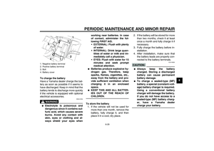
To store the battery
1. If the vehicle will not be used for
more than one month, remove the
battery, fully charge it, and then
place it in a cool, dry place.2. If the battery will be stored for more
than two months, check it at least
once a month and fully charge it if
necessary.
3. Fully charge the battery before in-
stallation.
4. After installation, make sure that
the battery leads are properly con-
nected to the battery terminals.
CAUTION:
ECA10630
�
Always keep the battery
charged. Storing a discharged
battery can cause permanent
battery damage.
�
To charge a sealed-type (MF)
battery, a special (constant-volt-
age) battery charger is required.
Using a conventional battery
charger will damage the battery.
If you do not have access to a
sealed-type (MF) battery charg-
er, have a Yamaha dealercharge your battery.
1. Negative battery terminal
2. Positive battery terminal
3. Bolt
4. Battery cover
Page 68 of 90

Fuse box 1 and fuse box 2 are located
under the seat. (See page 3-12.")
PERIODIC MAINTENANCE AND MINOR REPAIR
6-30
6
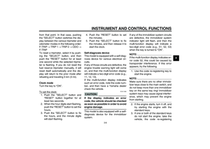
EAUM1740
Replacing the fuses The main fuse is located behind panel
A. (See page 6-5.)
Fuse box 1 and fuse box 2 are located
under the seat. (See page 3-12.)
If a fuse is blown, replace it as follows.
1. Turn the key to “OFF” and turn off
the electrical circuit in question.
2. Remove the blown fuse, and then
install a new fuse of the specified
amperage.
CAUTION:
ECA10640
Do not use a fuse of a higher amper-
age rating than recommended to
avoid causing extensive damage to
the electrical system and possibly afire.
3. Turn the key to “ON” and turn on
the electrical circuit in question to
check if the device operates.
1. Main fuse
2. Spare main fuse
1. Fuse box 1
2. Signaling system fuse
3. Headlight fuse
4. Ignition fuse
5. Electronic fuel injection fuse
6. Radiator fan fuse
7. Backup fuse (for odometer, clock and
immobilizer system)
8. Parking lighting fuse
9. Fuse box 2
10.Spare fuse
Specified fuses:
Main fuse:
30.0 A
Fuse box 1:
Headlight fuse:
20.0 A
Signaling system fuse:
10.0 A
Radiator fan fuse:
7.5 A
Ignition fuse:
10.0 A
Electronic fuel injection fuse:
10.0 A
Backup fuse:
10.0 A
Fuse box 2:
Parking lighting fuse:
10.0 A
Page 69 of 90

PERIODIC MAINTENANCE AND MINOR REPAIR
6-31
6 4. If the fuse immediately blows
again, have a Yamaha dealer
check the electrical system.
EAUM1750
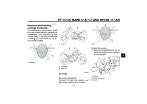
Replacing the headlight bulb This model is equipped with a quartz
bulb headlight. If the headlight bulb
burns out, replace it as follows.
1. Remove cowling A together with
the headlight unit. (See page 6-5.)
2. Disconnect the headlight coupler,
and then remove the headlight
bulb cover.
3. Remove the headlight bulb holder
by turning it counterclockwise, and
then remove the defective bulb.
WARNING
EWA10790
Headlight bulbs get very hot. There-
fore, keep flammable products away
from a lit headlight bulb, and do not
touch the bulb until it has cooleddown.
4. Place a new bulb into position, and
then secure it with the bulb holder.CAUTION:
ECA10660
Do not touch the glass part of the
headlight bulb to keep it free from
oil, otherwise the transparency of
the glass, the luminosity of the bulb,
and the bulb life will be adversely af-
1. Headlight bulb cover
2. Headlight coupler
1. Headlight bulb holder
2. Headlight bulb
Page 70 of 90
PERIODIC MAINTENANCE AND MINOR REPAIR
6-32
6fected. Thoroughly clean off any dirt
and fingerprints on the headlight
bulb using a cloth moistened with al-
cohol or thinner.
5. Install the bulb cover, and then
connect the coupler.
6. Install the cowling together with
the headlight unit.
7. Have a Yamaha dealer adjust the
headlight beam if necessary.
EAU24281
Replacing a turn signal light
bulb or the tail/brake light bulb 1. Remove the lens by removing the
screws.2. Remove the defective bulb by
pushing it in and turning it counter-
clockwise.
3. Insert a new bulb into the socket,
push it in, and then turn it clock-
wise until it stops.
4. Install the lens by installing the
screws.
CAUTION:
ECA10680
Do not overtighten the screws, oth-erwise the lens may break.
1. Do not touch the glass part of the bulb.
1. Screw
1. Screw
Page 71 of 90

PERIODIC MAINTENANCE AND MINOR REPAIR
6-33
6
EAUM1820
Replacing an auxiliary light
bulb If the auxiliary light bulb burns out, re-
place it as follows.
1. Remove cowling A together with
the headlight unit. (See page 6-5.)
2. Remove the auxiliary light socket
(together with the bulb) by pulling it
out.
3. Remove the defective bulb by pull-
ing it out.
4. Insert a new bulb into the socket.
5. Install the auxiliary light socket (to-
gether with the bulb) by pushing it
in.
6. Install the cowling together with
the headlight unit.
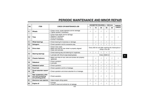
EAU24350
Supporting the motorcycle Since this model is not equipped with a
centerstand, follow these precautions
when removing the front and rear
wheel or performing other maintenance
requiring the motorcycle to stand up-
right. Check that the motorcycle is in a
stable and level position before starting
any maintenance. A strong wooden
box can be placed under the engine for
added stability.
To service the front wheel
1. Stabilize the rear of the motorcycle
by using a motorcycle stand or, if
an additional motorcycle stand is
not available, by placing a jack un-
der the frame in front of the rear
wheel.
2. Raise the front wheel off the
ground by using a motorcycle
stand.
To service the rear wheel
Raise the rear wheel off the ground by
using a motorcycle stand or, if a motor-
cycle stand is not available, by placinga jack either under each side of the
frame in front of the rear wheel or under
each side of the swingarm.
1. Auxiliary light bulb socket
Page 72 of 90

PERIODIC MAINTENANCE AND MINOR REPAIR
6-34
6
EAU24360
Front wheel
EAUM1761
To remove the front wheel
WARNING
EWA10820
�
It is advisable to have a Yamaha
dealer service the wheel.
�
Securely support the motor-
cycle so that there is no dangerof it falling over.
1. Loosen the front wheel axle pinch
bolts, then the wheel axle and the
brake caliper bolts.
XT660RXT660X
2. Lift the front wheel off the ground
according to the procedure on
page 6-33.
3. Remove the brake caliper by re-
moving the bolts.
CAUTION:
ECA11070
Do not apply the brake after the
wheel has been removed together
with the brake disc, otherwise thebrake pads will be forced shut.
4. Pull the wheel axle out, and then
remove the wheel.
EAUM1811
To install the front wheel
1. Lift the wheel up between the fork
legs.
2. Insert the wheel axle.
3. Lower the front wheel so that it is
on the ground.
1. Wheel axle
2. Front wheel axle pinch bolt A
3. Front wheel axle pinch bolt B
1. Wheel axle
2. Front wheel axle pinch bolt A
3. Front wheel axle pinch bolt B
1. Bolt
2. Brake caliper