Page 17 of 90

INSTRUMENT AND CONTROL FUNCTIONS
3-2
3
EAU10471
Main switch/steering lock The main switch/steering lock controls
the ignition and lighting systems, and is
used to lock the steering.NOTE:Be sure to use the standard key (black
bow) for regular use of the vehicle. To
minimize the risk of losing the code re-
registering key (red bow), keep it in a
safe place and only use it for code re-registering.
EAU10570
ON
All electrical circuits are supplied with
power; the meter lighting, taillight and
auxiliary light come on, and the engine
can be started. The key cannot be re-
moved.NOTE:The headlight comes on automatically
when the engine is started and stays onuntil the key is turned to “OFF”.
EAU10660
OFF
All electrical systems are off. The key
can be removed.
EAU10680
LOCK
The steering is locked, and all electrical
systems are off. The key can be re-
moved.To lock the steering
1. Turn the handlebars all the way to
the left.
2. Push the key in from the “OFF” po-
sition, and then turn it to “LOCK”
while still pushing it.
3. Remove the key.1. Push.
2. Turn.
Page 18 of 90

INSTRUMENT AND CONTROL FUNCTIONS
3-3
3To unlock the steering
Push the key in, and then turn it to
“OFF” while still pushing it.
WARNING
EWA10060
Never turn the key to “OFF” or
“LOCK” while the vehicle is moving,
otherwise the electrical systems will
be switched off, which may result in
loss of control or an accident. Make
sure that the vehicle is stopped be-
fore turning the key to “OFF” or“LOCK”.
EAU33000
(Parking)
The steering is locked, and the taillight
and auxiliary light are on. The hazard
light and turn signal lights can be turned
on, but all other electrical systems are
off. The key can be removed.
The steering must be locked before the
key can be turned to “”.
CAUTION:
ECA11020
Do not use the parking position for
an extended length of time, other-wise the battery may discharge.
EAU11001
Indicator and warning lights
EAU11020
Turn signal indicator light “”
This indicator light flashes when the
turn signal switch is pushed to the left or
right.
EAU11060
Neutral indicator light “”
This indicator light comes on when the
transmission is in the neutral position.
1. Push.
2. Turn.
1. Engine trouble warning light “”
2. Turn signal indicator light “”
3. Fuel level warning light “”
4. High beam indicator light “”
5. Neutral indicator light “”
6. Coolant temperature warning light “”
7. Immobilizer system indicator light “”
Page 19 of 90

INSTRUMENT AND CONTROL FUNCTIONS
3-4
3
EAU11080
High beam indicator light “”
This indicator light comes on when the
high beam of the headlight is switched
on.
EAU11360
Fuel level warning light “”
This warning light comes on when the
fuel level drops below approximately
5.0 L (1.32 US gal) (1.10 Imp.gal).
When this occurs, refuel as soon as
possible.
The electrical circuit of the warning light
can be checked by turning the key to
“ON”.
If the warning light does not come on
for a few seconds, then go off, have a
Yamaha dealer check the electrical cir-
cuit.NOTE:This model is also equipped with a self-
diagnosis device for the fuel level de-
tection circuit. If the fuel level detection
circuit is defective, the following cycle
will be repeated until the malfunction is
corrected: The fuel level warning lightwill flash eight times, then go off for 2.5
seconds. If this occurs, have a Yamaha
dealer check the vehicle.
EAU11440
Coolant temperature warning light
“”
This warning light comes on when the
engine overheats. When this occurs,
stop the engine immediately and allow
the engine to cool.
The electrical circuit of the warning light
can be checked by turning the key to
“ON”.
If the warning light does not come on
for a few seconds, then go off, have a
Yamaha dealer check the electrical cir-
cuit.CAUTION:
ECA10020
Do not operate the engine if it isoverheated.
EAU11530
Engine trouble warning light “”
This warning light comes on or flashes
when an electrical circuit monitoring the
engine is defective. When this occurs,
have a Yamaha dealer check the self-diagnosis system. (See page 3-5 for an
explanation of the self-diagnosis de-
vice.)
The electrical circuit of the warning light
can be checked by turning the key to
“ON”. If the warning light does not come
on for a few seconds, then go off, have
a Yamaha dealer check the electrical
circuit.
EAU26871
Immobilizer system indicator light
“”
The electrical circuit of the indicator
light can be checked by turning the key
to “ON”.
If the indicator light does not come on
for a few seconds, then go off, have a
Yamaha dealer check the electrical cir-
cuit.
When the key is turned to “OFF” and 30
seconds have passed, the indicator
light will start flashing indicating the im-
mobilizer system is enabled. After 24
hours have passed, the indicator light
will stop flashing, however the immobi-
lizer system is still enabled.
Page 20 of 90

INSTRUMENT AND CONTROL FUNCTIONS
3-5
3
NOTE:This model is also equipped with a self-
diagnosis device for the immobilizer
system. If the immobilizer system is de-
fective, the indicator will start flashing
and the multi-function meter will display
an error code when the key is turned to
“ON”. (See “Self-diagnosis device” onpage 3-5 for details.)
EAUM1662
Multi-function display The multi-function display is equipped
with the following:�
a speedometer (which shows the
riding speed)
�
an odometer (which shows the to-
tal distance traveled)
�
two tripmeters (which show the
distance traveled since they were
last set to zero)
�
a fuel reserve tripmeter (which
shows the distance traveled since
the fuel level warning light came
on)
�
a clock
�
a self-diagnosis device
NOTE:�
Be sure to turn the key to “ON” be-
fore using the “SELECT” and “RE-
SET” buttons.
�
For the U.K. only: To switch the
speedometer and odometer/trip-
meter displays between kilometers
and miles, press the “SELECT”button for at least two seconds.
Odometer and tripmeter modes
Pushing the “SELECT” button switches
the display between the odometer
mode “ODO” and the tripmeter modes
“TRIP 1” and “TRIP 2” in the following
order:
ODO → TRIP 1 → TRIP 2 → ODO
If the fuel level warning light comes on
(see page 3-3), the odometer display
will automatically change to the fuel re-
serve tripmeter mode “F-TRIP” and
start counting the distance traveled
1. Multi-function display
2. Clock
3. Tripmeter 1
4. Odometer/fuel reserve tripmeter/tripmeter 2
5.“SELECT” button
6.“RESET” button
7. Speedometer
Page 21 of 90

INSTRUMENT AND CONTROL FUNCTIONS
3-6
3 from that point. In that case, pushing
the “SELECT” button switches the dis-
play between the various tripmeter and
odometer modes in the following order:
F-TRIP → TRIP 1 → TRIP 2 → ODO →
F-TRIP
To reset a tripmeter, select it by push-
ing the “SELECT” button, and then
push the “RESET” button for at least
one second while the selected tripme-
ter is flashing. If you do not reset the
fuel reserve tripmeter manually, it will
reset itself automatically and the dis-
play will return to the prior mode after
refueling and traveling 5 km (3 mi).
Clock mode
Turn the key to “ON”.
To set the clock:
1. Push the “SELECT” button and
“RESET” button together for at
least two seconds.
2. When the hour digits start flashing,
push the “RESET” button to set the
hours.
3. Push the “SELECT” button to fix
the hours, and the minute digits
will start flashing.4. Push the “RESET” button to set
the minutes.
5. Push the “SELECT” button to fix
the minutes, and then release it to
start the clock.
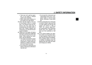
Self-diagnosis device
This model is equipped with a self-diag-
nosis device for various electrical cir-
cuits.
If any of those circuits are defective, the
engine trouble warning light will come
on, and then the multi-function display
will indicate a two-digit error code (e.g.,
11, 12, 13).
If the multi-function display indicates
such an error code, note the code num-
ber, and then have a Yamaha dealer
check the vehicle.
CAUTION:
ECA11590
If the display indicates an error
code, the vehicle should be checked
as soon as possible in order to avoidengine damage.
This model is also equipped with a self-
diagnosis device for the immobilizer
system.If any of the immobilizer system circuits
are defective, the immobilizer system
indicator light will flash, and then the
multi-function display will indicate a
two-digit error code (e.g., 51, 52, 53)
when the key is turned to “ON”.
NOTE:If the multi-function display indicates er-
ror code 52, this could be caused by
transponder interference. If this errorappears, try the following.
1. Use the code re-registering key to
start the engine.NOTE:Make sure there are no other immobi-
lizer keys close to the main switch, and
do not keep more than one immobilizer
key on the same key ring! Immobilizer
system keys may cause signal interfer-
ence, which may prevent the enginefrom starting.
2. If the engine starts, turn it off, and
try starting the engine with the
standard keys.
3. If one or both of the standard keys
do not start the engine, take the
vehicle, the code re-registering
Page 22 of 90
INSTRUMENT AND CONTROL FUNCTIONS
3-7
3key and both standard keys to a
Yamaha dealer and have the stan-
dard keys re-registered.
If the multi-function display indicates
any error codes, note the code number,
and then have a Yamaha dealer check
the vehicle.
EAU12330
Anti-theft alarm (optional) This model can be equipped with an
optional anti-theft alarm by a Yamaha
dealer. Contact a Yamaha dealer for
more information.
EAU12343
Handlebar switches Left1. Pass switch “”
2. Dimmer switch “/”
3. Turn signal switch “/”
4. Horn switch “”
5. Hazard switch “”
Page 23 of 90

INSTRUMENT AND CONTROL FUNCTIONS
3-8
3 Right
EAU12350
Pass switch “”
Press this switch to flash the headlight.
EAU12400
Dimmer switch “/”
Set this switch to “” for the high
beam and to “” for the low beam.
EAU12460
Turn signal switch “/”
To signal a right-hand turn, push this
switch to “”. To signal a left-hand
turn, push this switch to “”. When re-
leased, the switch returns to the centerposition. To cancel the turn signal
lights, push the switch in after it has re-
turned to the center position.
EAU12500
Horn switch “”
Press this switch to sound the horn.
EAU12660
Engine stop switch “/”
Set this switch to “” before starting
the engine. Set this switch to “” to
stop the engine in case of an emergen-
cy, such as when the vehicle overturns
or when the throttle cable is stuck.
EAU12710
Start switch “”
Push this switch to crank the engine
with the starter.CAUTION:
ECA10050
See page 5-1 for starting instruc-tions prior to starting the engine.
EAU12731
Hazard switch “”
With the key in the “ON” or “” posi-
tion, use this switch to turn on the haz-
ard light (simultaneous flashing of all
turn signal lights).
The hazard light is used in case of an
emergency or to warn other drivers
when your vehicle is stopped where it
might be a traffic hazard.CAUTION:
ECA10060
Do not use the hazard light for an ex-
tended length of time, otherwise thebattery may discharge.
1. Engine stop switch “/”
2. Start switch “”
Page 24 of 90
INSTRUMENT AND CONTROL FUNCTIONS
3-9
3
EAU12820
Clutch lever The clutch lever is located at the left
handlebar grip. To disengage the
clutch, pull the lever toward the handle-
bar grip. To engage the clutch, release
the lever. The lever should be pulled
rapidly and released slowly for smooth
clutch operation.
The clutch lever is equipped with a
clutch switch, which is part of the igni-
tion circuit cut-off system. (See page
3-15.)
EAU12870
Shift pedal The shift pedal is located on the left
side of the engine and is used in com-
bination with the clutch lever when
shifting the gears of the 5-speed con-
stant-mesh transmission equipped on
this motorcycle.
EAU12890
Brake lever The brake lever is located at the right
handlebar grip. To apply the front
brake, pull the lever toward the handle-
bar grip.
1. Clutch lever
1. Shift pedal
1. Brake lever