Page 49 of 90

PERIODIC MAINTENANCE AND MINOR REPAIR
6-8
6 2. Clean the surface of the spark plug
gasket and its mating surface, and
then wipe off any grime from the
spark plug threads.
3. Install the spark plug with the
spark plug wrench, and then tight-
en it to the specified torque.
NOTE:
If a torque wrench is not available when
installing a spark plug, a good estimate
of the correct torque is 1/4–1/2 turn
past finger tight. However, the spark
plug should be tightened to the speci-fied torque as soon as possible.
4. Install the spark plug cap.
EAU19691
Engine oil and oil filter
element The engine oil level should be checked
before each ride. In addition, the oil
must be changed and the oil filter ele-
ment replaced at the intervals specified
in the periodic maintenance and lubri-
cation chart.
To check the engine oil level
1. Place the vehicle on the center-
stand.NOTE:
Make sure that the vehicle is positioned
straight up when checking the oil level.
A slight tilt to the side can result in afalse reading.
2. Start the engine, warm it up for
several minutes, and then turn it
off.
3. Wait a few minutes until the oil set-
tles, and then check the oil level
through the check window located
at the bottom-right side of the
crankcase.
NOTE:The engine oil should be between theminimum and maximum level marks.
4. If the engine oil is below the mini-
mum level mark, add sufficient oil
of the recommended type to raise
it to the correct level.
To change the engine oil (with or
without oil filter element replace-
ment)
1. Start the engine, warm it up for
several minutes, and then turn it
off.
Tightening torque:
Spark plug:
17.5 Nm (1.75 m·kgf, 13 ft·lbf)
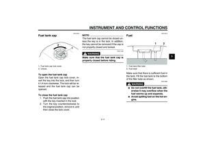
1. Engine oil filler cap
2. Engine oil level check window
3. Maximum level mark
4. Minimum level mark
U5WME1E0.book Page 8 Thursday, September 11, 2003 11:10 AM
Page 50 of 90

PERIODIC MAINTENANCE AND MINOR REPAIR
6-9
62. Place an oil pan under the engine
to collect the used oil.
3. Remove the engine oil filler cap
and drain bolt to drain the oil from
the crankcase.
NOTE:
Skip steps 4–10 if the oil filter elementis not being replaced.
4. Remove panel C. (See page 6-5.)
5. Remove the oil filter element drain
screw to drain the oil from the oil fil-
ter element.
6. Remove the oil filter element cover
by removing the bolt.7. Remove and replace the oil filter
element and O-ring.8. Install the oil filter element cover by
aligning the projection on the cover
with the slot in the crankcase, in-
stalling the bolt, then tightening it
to the specified torque.
NOTE:Make sure that the O-ring is properlyseated.
9. Install the oil filter element drain
screw, and then tighten it to the
specified torque.
1. Engine oil drain bolt
1. Oil filter element drain screw
2. Bolt
3. Oil filter element cover
1. Oil filter element
2. O-ring
1. Projection
2. SlotTightening torque:
Oil filter element cover bolt:
15 Nm (1.5 m·kgf, 11 ft·lbf)
U5WME1E0.book Page 9 Thursday, September 11, 2003 11:10 AM
Page 51 of 90

PERIODIC MAINTENANCE AND MINOR REPAIR
6-10
6 10. Install the panel.
11. Install the engine oil drain bolt, and
then tighten it to the specified
torque.
12. Add the specified amount of the
recommended engine oil, and then
install and tighten the oil filler cap.
CAUTION:
ECA11620
�
In order to prevent clutch slip-
page (since the engine oil also
lubricates the clutch), do notmix any chemical additives. Do
not use oils with a diesel speci-
fication of “CD” or oils of a high-
er quality than specified. In
addition, do not use oils labeled
“ENERGY CONSERVING II” or
higher.
�
Make sure that no foreign mate-rial enters the crankcase.
13. Start the engine, and then let it idle
for several minutes while checking
it for oil leakage. If oil is leaking, im-
mediately turn the engine off and
check for the cause.
NOTE:After the engine is started, the engine
oil level warning light should go off if theoil level is sufficient.CAUTION:
ECA10400
If the oil level warning light flickers
or remains on, immediately turn the
engine off and have a Yamaha dealercheck the vehicle.
14. Turn the engine off, and then
check the oil level and correct it if
necessary.
EAU20610
Cleaning the air filter element The air filter element should be cleaned
at the intervals specified in the periodic
maintenance and lubrication chart.
Clean the air filter element more fre-
quently if you are riding in unusually
wet or dusty areas.
1. Remove the seat. (See page
3-14.)
2. Remove panel A. (See page 6-5.)
3. Remove the air filter case cover by
removing the screws.
4. Pull the air filter element out.
Tightening torque:
Oil filter element drain screw:
7 Nm (0.7 m·kgf, 5 ft·lbf)
Tightening torque:
Engine oil drain bolt:
43 Nm (4.3 m·kgf, 31 ft·lbf)
Recommended engine oil:
See page 8-1.
Oil quantity:
Without oil filter element replace-
ment:
3.00 L (3.17 US qt) (2.64 Imp.qt)
With oil filter element replacement:
3.35 L (3.54 US qt) (2.95 Imp.qt)
1. Air filter case cover
2. Screw
U5WME1E0.book Page 10 Thursday, September 11, 2003 11:10 AM
Page 52 of 90

PERIODIC MAINTENANCE AND MINOR REPAIR
6-11
65. Lightly tap the air filter element to
remove most of the dust and dirt,
and then blow the remaining dirt
out with compressed air as shown.
If the air filter element is damaged,
replace it.
6. Insert the air filter element into the
air filter case.
CAUTION:
ECA10480
�
Make sure that the air filter ele-
ment is properly seated in the
air filter case.
�
The engine should never be op-
erated without the air filter ele-
ment installed, otherwise the
piston(s) and/or cylinder(s) maybecome excessively worn.
7. Install the air filter case cover by in-
stalling the screws.
8. Install the panel and the seat.
EAU21290
Adjusting the carburetors The carburetors are important parts of
the engine and require very sophisticat-
ed adjustment. Therefore, most carbu-
retor adjustments should be left to a
Yamaha dealer, who has the neces-
sary professional knowledge and expe-
rience. The adjustment described in the
following section, however, may be ser-
viced by the owner as part of routine
maintenance.CAUTION:
ECA10560
The carburetors have been set and
extensively tested at the Yamaha
factory. Changing these settings
without sufficient technical knowl-
edge may result in poor perfor-mance of or damage to the engine.
1. Air filter elementU5WME1E0.book Page 11 Thursday, September 11, 2003 11:10 AM
Page 53 of 90

PERIODIC MAINTENANCE AND MINOR REPAIR
6-12
6
EAU21320
Adjusting the engine idling
speed The engine idling speed must be
checked and, if necessary, adjusted as
follows at the intervals specified in the
periodic maintenance and lubrication
chart.
The engine should be warm before
making this adjustment.NOTE:
The engine is warm when it quickly re-sponds to the throttle.
Check the engine idling speed and, if
necessary, adjust it to specification by
turning the throttle stop screw. To in-
crease the engine idling speed, turn the
screw in direction (a). To decrease the
engine idling speed, turn the screw in
direction (b).
NOTE:
If the specified idling speed cannot be
obtained as described above, have aYamaha dealer make the adjustment.
EAU21380
Adjusting the throttle cable
free play The throttle cable free play should mea-
sure 3.0–5.0 mm (0.12–0.20 in) at the
throttle grip. Periodically check the
throttle cable free play and, if neces-
sary, have a Yamaha dealer adjust it.
1. Throttle stop screw
Engine idling speed:
950–1150 r/min
1. Throttle cable free play
U5WME1E0.book Page 12 Thursday, September 11, 2003 11:10 AM
Page 54 of 90

PERIODIC MAINTENANCE AND MINOR REPAIR
6-13
6
EAU21400
Adjusting the valve clearance The valve clearance changes with use,
resulting in improper air-fuel mixture
and/or engine noise. To prevent this
from occurring, the valve clearance
must be adjusted by a Yamaha dealer
at the intervals specified in the periodic
maintenance and lubrication chart.
EAU21771
Tires To maximize the performance, durabil-
ity, and safe operation of your motor-
cycle, note the following points
regarding the specified tires.
Tire air pressure
The tire air pressure should be checked
and, if necessary, adjusted before each
ride.
WARNING
EWA10500
�
The tire air pressure must be
checked and adjusted on cold
tires (i.e., when the temperature
of the tires equals the ambient
temperature).
�
The tire air pressure must be ad-
justed in accordance with the
riding speed and with the total
weight of rider, passenger, car-
go, and accessories approvedfor this model.
WARNING
EWA11020
Because loading has an enormous
impact on the handling, braking,
performance and safety characteris-
tics of your motorcycle, you should
keep the following precautions in
mind.Tire air pressure (measured on cold
tires):
0–90 kg (0–198 lb):
Front:
250 kPa (36 psi) (2.50 kgf/cm²)
Rear:
250 kPa (36 psi) (2.50 kgf/cm²)
90–203 kg (198–448 lb):
Front:
250 kPa (36 psi) (2.50 kgf/cm²)
Rear:
290 kPa (42 psi) (2.90 kgf/cm²)
High-speed riding:
Front:
250 kPa (36 psi) (2.50 kgf/cm²)
Rear:
290 kPa (42 psi) (2.90 kgf/cm²)
Maximum load*:
203 kg (448 lb)
* Total weight of rider, passenger, car-
go and accessories
U5WME1E0.book Page 13 Thursday, September 11, 2003 11:10 AM
Page 55 of 90

PERIODIC MAINTENANCE AND MINOR REPAIR
6-14
6
�
NEVER OVERLOAD THE
MOTORCYCLE! Operation of an
overloaded motorcycle may re-
sult in tire damage, loss of con-
trol, or severe injury. Make sure
that the total weight of rider,
passenger, cargo, and accesso-
ries does not exceed the speci-
fied maximum load for the
vehicle.
�
Do not carry along loosely
packed items, which can shift
during a ride.
�
Securely pack the heaviest
items close to the center of the
motorcycle and distribute the
weight evenly on both sides.
�
Adjust the suspension and tire
air pressure with regard to the
load.
�
Check the tire condition and airpressure before each ride.Tire inspection
The tires must be checked before each
ride. If the center tread depth reaches
the specified limit, if the tire has a nail or
glass fragments in it, or if the sidewall is
cracked, have a Yamaha dealer re-
place the tire immediately.
NOTE:The tire tread depth limits may differ
from country to country. Always complywith the local regulations.
WARNING
EWA10470
�
Have a Yamaha dealer replace
excessively worn tires. Besides
being illegal, operating the vehi-
cle with excessively worn tires
decreases riding stability and
can lead to loss of control.
�
The replacement of all wheel
and brake related parts, includ-
ing the tires, should be left to a
Yamaha dealer, who has the
necessary professional knowl-edge and experience.
Tire information
1. Tire sidewall
2. Tire tread depth
Minimum tire tread depth (front and
rear):
1.6 mm (0.06 in)
1. Tire air valve
2. Tire air valve core
3. Tire air valve cap with seal
U5WME1E0.book Page 14 Thursday, September 11, 2003 11:10 AM
Page 56 of 90

PERIODIC MAINTENANCE AND MINOR REPAIR
6-15
6This motorcycle is equipped with cast
wheels and tubeless tires with valves.
WARNING
EWA10480
�
The front and rear tires should
be of the same make and de-
sign, otherwise the handling
characteristics of the motor-
cycle cannot be guaranteed.
�
After extensive tests, only the
tires listed below have been ap-
proved for this model by
Yamaha Motor Co., Ltd.
�
Always make sure that the valve
caps are securely installed to
prevent air pressure leakage.
�
Use only the tire valves and
valve cores listed below to
avoid tire deflation during ahigh-speed ride.
WARNING
EWA10600
This motorcycle is fitted with super-
high-speed tires. Note the following
points in order to make the most ef-
ficient use of these tires.�
Use only the specified replace-
ment tires. Other tires may run
the danger of bursting at super
high speeds.
�
Brand-new tires can have a rela-
tively poor grip on certain road
surfaces until they have been
“broken in”. Therefore, it is ad-
visable before doing any high-speed riding to ride conserva-
tively for approximately 100 km
(60 mi) after installing a new tire.
�
The tires must be warmed up
before a high-speed run.
�
Always adjust the tire air pres-
sure according to the operatingconditions.
Front tire:
Size:
120/70 ZR17M/C (58W)
Manufacturer/model:
DUNLOP/D252FJ
Rear tire:
Size:
180/55 ZR17M/C (73W)
Manufacturer/model:
DUNLOP/D252J
FRONT and REAR:
Tire air valve:
TR412
Va l ve c o r e :
#9000A (original)
U5WME1E0.book Page 15 Thursday, September 11, 2003 11:10 AM