Page 25 of 90

INSTRUMENT AND CONTROL FUNCTIONS
3-11
3
EAU13070
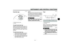
Fuel tank cap To open the fuel tank cap
Open the fuel tank cap lock cover, in-
sert the key into the lock, and then turn
it 1/4 turn clockwise. The lock will be re-
leased and the fuel tank cap can be
opened.
To close the fuel tank cap
1. Push the fuel tank cap into position
with the key inserted in the lock.
2. Turn the key counterclockwise to
the original position, remove it, and
then close the lock cover.
NOTE:The fuel tank cap cannot be closed un-
less the key is in the lock. In addition,
the key cannot be removed if the cap isnot properly closed and locked.
WARNING
EWA11090
Make sure that the fuel tank cap isproperly closed before riding.
EAU13210
Fuel Make sure that there is sufficient fuel in
the tank. Fill the fuel tank to the bottom
of the filler tube as shown.
WARNING
EWA10880
�
Do not overfill the fuel tank, oth-
erwise it may overflow when the
fuel warms up and expands.
�
Avoid spilling fuel on the hot en-gine.
1. Fuel tank cap lock cover
2. Unlock.
1. Fuel tank filler tube
2. Fuel level
U5WME1E0.book Page 11 Thursday, September 11, 2003 11:10 AM
Page 26 of 90

INSTRUMENT AND CONTROL FUNCTIONS
3-12
3
CAUTION:
ECA10070
Immediately wipe off spilled fuel
with a clean, dry, soft cloth, since
fuel may deteriorate painted surfac-es or plastic parts.
EAU13320
CAUTION:
ECA11400
Use only unleaded gasoline. The use
of leaded gasoline will cause severe
damage to internal engine parts,
such as the valves and piston rings,as well as to the exhaust system.
Your Yamaha engine has been de-
signed to use regular unleaded gaso-
line with a research octane number of
91 or higher. If knocking (or pinging) oc-
curs, use a gasoline of a different brandor premium unleaded fuel. Use of un-
leaded fuel will extend spark plug life
and reduce maintenance costs.
EAU13410
Fuel tank breather hose Before operating the motorcycle:�
Check the fuel tank breather hose
connection.
�
Check the fuel tank breather hose
for cracks or damage, and replace
it if damaged.
�
Make sure that the end of the fuel
tank breather hose is not blocked,
and clean it if necessary.
Recommended fuel:
REGULAR UNLEADED GASOLINE
ONLY
Fuel tank capacity:
21.0 L (5.55 US gal) (4.62 Imp.gal)
Fuel reserve amount:
4.5 L (1.19 US gal) (0.99 Imp.gal)
1. Fuel tank breather hose
2. Original position (white marks)
U5WME1E0.book Page 12 Thursday, September 11, 2003 11:10 AM
Page 27 of 90

INSTRUMENT AND CONTROL FUNCTIONS
3-13
3
EAU13440
Catalytic converter This vehicle is equipped with a catalytic
converter in the muffler.
WARNING
EWA10860
The exhaust system is hot after op-
eration. Make sure that the exhaust
system has cooled down before do-ing any maintenance work.CAUTION:
ECA10700
The following precautions must be
observed to prevent a fire hazard or
other damages.�
Use only unleaded gasoline.
The use of leaded gasoline will
cause unrepairable damage to
the catalytic converter.
�
Never park the vehicle near pos-
sible fire hazards such as grass
or other materials that easily
burn.
�
Do not allow the engine to idletoo long.
EAU13570
Fuel cock The fuel cock supplies fuel from the
tank to the carburetors while also filter-
ing it.
The fuel cock lever positions are ex-
plained as follows and shown in the il-
lustrations.
ON
With the fuel cock lever in this position,
fuel flows to the carburetors when the
engine is running. Turn the fuel cock le-
ver to this position when starting the en-
gine and riding.RES
This indicates reserve. With the fuel
cock lever in this position, the fuel re-
serve is made available. Quickly turn
the fuel cock lever to this position if you
run out of fuel while riding, otherwise
the engine may stall and will have to be
primed (see “PRI”). After turning the
fuel cock lever to “RES”, refuel as soon
as possible and be sure to turn the fuel
cock lever back to “ON”!1. Arrow mark positioned over “ON”
1. Arrow mark positioned over “RES”
U5WME1E0.book Page 13 Thursday, September 11, 2003 11:10 AM
Page 28 of 90

INSTRUMENT AND CONTROL FUNCTIONS
3-14
3PRI
This indicates prime. With the fuel cock
lever in this position, the engine can be
“primed”. Turn the fuel cock lever to this
position when the engine has been al-
lowed to run out of fuel. This sends fuel
directly to the carburetors, which will
make starting easier. After the engine
has started, be sure to turn the lever to
“ON” (or “RES” if you have not refueled
yet).
EAU13590
Starter (choke) lever “” Starting a cold engine requires a richer
air-fuel mixture, which is supplied by
the starter (choke).
Move the lever in direction (a) to turn on
the starter (choke).
Move the lever in direction (b) to turn off
the starter (choke).
EAU13900
Seat To remove the seat
1. Insert the key into the seat lock,
and then turn it as shown.
2. Pull the seat off.
To install the seat
1. Insert the projection on the front of
the seat into the seat holder as
shown.
1. Arrow mark positioned over “PRI”
1. Starter (choke) lever “”
1. Unlock.
U5WME1E0.book Page 14 Thursday, September 11, 2003 11:10 AM
Page 29 of 90

INSTRUMENT AND CONTROL FUNCTIONS
3-15
3
2. Push the rear of the seat down to
lock it in place.
3. Remove the key.
NOTE:Make sure that the seat is properly se-cured before riding.
EAU14350
Helmet holder To open the helmet holder, insert the
key into the seat lock, and then turn the
key as shown.
To lock the helmet holder, turn the key
to the original position, and then re-
move it.
WARNING
EWA10160
Never ride with a helmet attached to
the helmet holder, since the helmet
may hit objects, causing loss of con-trol and possibly an accident.
EAU14411
Storage compartment This storage compartment is designed
to hold an optional genuine Yamaha U-
LOCK. (Other locks may not fit.) When
placing a U-LOCK in the storage com-
partment, securely fasten it with the
straps. When the U-LOCK is not in the
storage compartment, be sure to se-
cure the straps to prevent losing them.
When storing the owner’s manual or
other documents in the storage com-
partment, be sure to wrap them in a
plastic bag so that they will not get wet.
1. Projection
2. Seat holder
1. Unlock.
1. U-LOCK bar (optional)
2. Strap
3. Lock of U-LOCK (optional)
U5WME1E0.book Page 15 Thursday, September 11, 2003 11:10 AM
Page 30 of 90
INSTRUMENT AND CONTROL FUNCTIONS
3-16
3When washing the motorcycle, be
careful not to let any water enter the
storage compartment.
EAU14720
Adjusting the front fork This front fork is equipped with spring
preload adjusting bolts.
WARNING
EWA10180
Always adjust both fork legs equal-
ly, otherwise poor handling and lossof stability may result.
Adjust the spring preload as follows.
To increase the spring preload and
thereby harden the suspension, turn
the adjusting bolt on each fork leg in di-
rection (a). To decrease the spring pre-
load and thereby soften the
suspension, turn the adjusting bolt on
each fork leg in direction (b).
NOTE:Align the appropriate groove on the ad-
justing mechanism with the top of thefront fork cap bolt.
1. Spring preload adjusting bolt
1. Current setting
2. Front fork cap boltSpring preload setting:
Minimum (soft):
7
Standard:
5
Maximum (hard):
1
U5WME1E0.book Page 16 Thursday, September 11, 2003 11:10 AM
Page 31 of 90

INSTRUMENT AND CONTROL FUNCTIONS
3-17
3
EAU14900
Adjusting the shock absorber
assemblies Each shock absorber assembly is
equipped with a spring preload adjust-
ing ring.CAUTION:
ECA10100
Never attempt to turn an adjusting
mechanism beyond the maximum orminimum settings.
WARNING
EWA10210
Always adjust both shock absorber
assemblies equally, otherwise poor
handling and loss of stability mayresult.
Adjust the spring preload as follows,
using the special wrenches included
along with the owner’s tool kit.
To increase the spring preload and
thereby harden the suspension, hold
the upper ring in place while turning the
lower ring (adjusting ring) on each
shock absorber assembly as shown in
direction (a).To decrease the spring preload and
thereby soften the suspension, hold the
upper ring in place while turning the
lower ring (adjusting ring) on each
shock absorber assembly as shown in
direction (b).
WARNING
EWA10230
These shock absorbers contain
highly pressurized nitrogen gas. For
proper handling read and under-
stand the following information be-
fore handling the shock absorbers.
The manufacturer cannot be held re-
sponsible for property damage or
personal injury that may result from
improper handling.
1. Upper ring
2. Lower ring (spring preload adjusting ring)
1. Upper ring
2. Lower ring (spring preload adjusting ring)
Setting:
Minimu (soft) / standard
Medium
Maximum (hard)
U5WME1E0.book Page 17 Thursday, September 11, 2003 11:10 AM
Page 32 of 90

INSTRUMENT AND CONTROL FUNCTIONS
3-18
3
�
Do not tamper with or attempt to
open the gas cylinders.
�
Do not subject the shock ab-
sorbers to an open flame or oth-
er high heat sources, otherwise
they may explode due to exces-
sive gas pressure.
�
Do not deform or damage the
gas cylinders in any way, as this
will result in poor damping per-
formance.
�
Always have a Yamaha dealerservice the shock absorbers.
EAU15230
Luggage strap holders There are four luggage strap holders,
two of which can be turned out for eas-
ier access.
EAU15300
Sidestand The sidestand is located on the left side
of the frame. Raise the sidestand or
lower it with your foot while holding the
vehicle upright.NOTE:The built-in sidestand switch is part of
the ignition circuit cut-off system, which
cuts the ignition in certain situations.
(See further down for an explanation ofthe ignition circuit cut-off system.)
WARNING
EWA10240
The vehicle must not be ridden with
the sidestand down, or if the side-
stand cannot be properly moved up
(or does not stay up), otherwise the
sidestand could contact the ground
and distract the operator, resulting
in a possible loss of control.
Yamaha’s ignition circuit cut-off
system has been designed to assist
the operator in fulfilling the respon-
sibility of raising the sidestand be-
fore starting off. Therefore, check
this system regularly as described
1. Luggage strap holder
U5WME1E0.book Page 18 Thursday, September 11, 2003 11:10 AM