Page 25 of 96

INSTRUMENT AND CONTROL FUNCTIONS
1
EAU00185
Immediately wipe off spilled fuel with a
clean, dry, soft cloth, since fuel may
deteriorate painted surfaces or plastic
parts.
CAUTION:
EAU00191
NOTE:
If knocking (or pinging) occurs, use gaso-
line of a different brand or with a higher
octane grade.Recommended fuel:
Regular unleaded gasoline with a
research octane number of 91 or
higher
Fuel tank capacity:
Total amount:
20 L
Reserve amount:
5.8 L
1. Fuel tank breather hose
EAU02955
Fuel tank breather hose
Before operating the motorcycle:
Check the fuel tank breather hose connec-
tion.
Check the fuel tank breather hose for
cracks or damage, and replace it if dam-
aged.
Make sure that the end of the fuel tank
breather hose is not blocked, and clean it if
necessary.
EAU03839
Starter (choke) lever
Starting a cold engine requires a richer air-
fuel mixture, which is supplied by the
starter (choke).
Move the lever in direction bto turn on
the starter (choke).
Move the lever in direction ato turn off
the starter (choke).
1
b
a
1. Starter (choke) lever
3-12
3
EAU00027
Page 26 of 96
INSTRUMENT AND CONTROL FUNCTIONS
1
��
ECA00038
Do not use the starter (choke) for more
than 3 minutes as the exeaust pipe may
discolor from excessive heat. In addi-
tion, extended use of the starter
(choke) will cause afterburning. If this
occurs, turn off the starter (choke).
CAUTION:
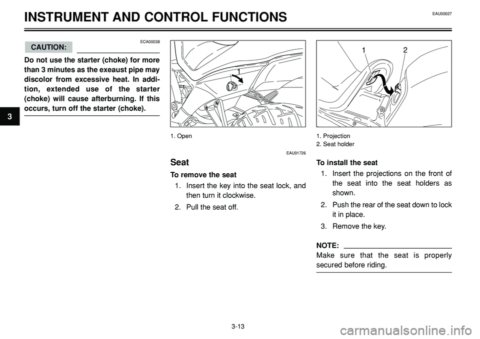
EAU01726
Seat
To remove the seat
1. Insert the key into the seat lock, and
then turn it clockwise.
2. Pull the seat off.
1. Open 1. Projection
2. Seat holder
To install the seat
1. Insert the projections on the front of
the seat into the seat holders as
shown.
2. Push the rear of the seat down to lock
it in place.
3. Remove the key.
NOTE:
Make sure that the seat is properly
secured before riding.
EAU00027
3-13
3
Page 27 of 96

1
3
INSTRUMENT AND CONTROL FUNCTIONS
1. Helmet holders
12
1. Storage compartment
2. Yamaha U-LOCK
1
1. Tool kit compartment
EAUB0005
Helmet holders
The helmet holders are located under the
seat. Each of the two helmet-holding ca-
bles provided can be used to secure a hel-
met to either helmet holder
To secure a helmet to a helmet holder
1. Remove the seat. (See page 3-13 for
removal and installation procedures).
2. Pass the helmet holding cable
through the buckle on the helmet
strap as shown, and then hook the
cable loop over the helmet holder.
3. Install the seat.
EWA00015WARNING0
Never ride with a helmet attached to a
helmet holder, since the helmet may hit
objects, causing loss of control and
possibly an accident.
EAUB0006
Storage compartment
The storage compartment is located under
the seat. (See page 3-13 for seat removal
and installation procedures).
This storage compartment is designed to
hold a genuine Yamaha U-LOCK. (Other
locks may not fit).
The tool kit is located at the back of the
storage compartment and held in place
with a strap.
When storing the owner’s manual or other
documents in the storage compartment,
be sure to wrap them in a plastic bag so
that they will not get wet. When washing
the motorcycle, be careful not to let any
water enter the storage compartment.
3-14
EAU00027
Page 28 of 96

INSTRUMENT AND CONTROL FUNCTIONS
1. Spring preload adjusting bolt 1. Setting
2. Front fork cap bolt
��
�
� �
1. Spring preload adjusting nut
2. Locknut
EAU00285
Adjusting the front fork
This front fork is equipped with spring pre-
load adjusting bolts.
EW000035WARNING0
Always adjust both fork legs equally,
otherwise poor handling and loss of
stability may result.
Adjust the spring preload as follows.
To increase the spring preload and thereby
harden the suspension, turn the adjusting
bolt on each fork leg in direction a. To de-
crease the spring preload and thereby
soften the suspension, turn the adjusting
bolt on each fork leg in direction b.
NOTE:
Align the appropriate groove on the adjust-
ing mechanism with the top of the front
fork cap bolt.
EAUB0007
Adjusting the shock absorber
assembly
This shock absorber assembly is equipped
with a spring preload adjusting nut.
EC000015
Never attempt to turn an adjusting
mechanism beyond the maximum or
minimum settings.
Adjust the spring preload as follows.
1. Loosen the locknut.
2. To increase the spring preload and
thereby harden the suspension, turn
the adjusting nut in direction a. To
CAUTION:
3-15
3
EAU00027
Minimum (soft) Standard Maximum (hard)
Setting 1 2 3 4 5 6 7
Page 29 of 96

INSTRUMENT AND CONTROL FUNCTIONS
decrease the spring preload and
thereby soften the suspension, turn
the adjusting nut in direction b.
NOTE:
Use the special wrench included in the
owner’s tool kit to make the adjustment.
The spring preload setting is determined
by measuring distance A, shown in the
illustration. The longer distance A is, the
higher the spring preload; the shorter dis-
tance A is, the lower the spring preload.
With each complete turn of the adjusting
nut, distance A changes by 1.5 mm.3. Tighten the locknut to the specified
torque.• Always have a Yamaha dealer ser-
vice the shock absorber.
EAU00330
Sidestand
The sidestand is located on the left side of
the frame. Raise the sidestand or lower it
with your foot while holding the motorcycle
upright.
NOTE:
The built-in sidestand switch is part of the
ignition circuit cut-off system, which cuts
the ignition in certain situations. (See fur-
ther down for an explanation of the ignition
circuit cut-off system).
3-16
3
Spring preload:
Minimum (soft):
Distance A = 170 mm
Standard:
Distance A = 162 mm
Maximum (hard):
Distance A = 154 mm
Tightening torque:
Locknut:
45 Nm (4.5 m•kg)
EAU00315WARNING0
This shock absorber contains highly
pressurized nitrogen gas. For proper
handling, read and understand the fol-
lowing information before handling the
shock absorber. The manufacturer can-
not be held responsible for property
damage or personal injury that may
result from improper handling.
•Do not tamper with or attempt to
open the gas cylinder.
•Do not subject the shock absorber
to an open flame or other high heat
sources, otherwise it may explode
due to excessive gas pressure.
•Do not deform or damage the gas
cylinder in any way, as this will
result in poor damping perfor-
mance.
EAU00027
Page 59 of 96
EAU00462PERIODIC MAINTENANCE AND MINOR REPAIR
2
1
c
b
a
Ride at moderate speeds after changing a
tire since the tire surface must first be “bro-
ken in” for it to develop its optimal charac-
teristics.
1. Locknut
2. Free play adjusting bolt
c. Clutch lever free play
EAU00692
Adjusting the clutch lever
free play
The clutch lever free play should measure
5-10 mm as shown. Periodically check the
clutch lever free play and, if necessary, ad-
just it as follows.1. Loosen the locknut at the clutch lever.
2. To increase the clutch lever free play,
turn the adjusting bolt in direction a.
To decrease the clutch lever free play,
turn the adjusting bolt in direction b.
3. Tighten the locknut.
NOTE:
If the specified free play cannot be
obtained as described above or if the
clutch does not operate correctly, have a
Yamaha dealer check the internal clutch
mechanism.
6-17
6
Page 62 of 96

EAU00462PERIODIC MAINTENANCE AND MINOR REPAIR
1
2
Observe these precautions:
•When checking the fluid level, make
sure that the top of the brake fluid
reservoir is level.
•Use only the recommended quality
brake fluid, otherwise the rubber
seals may deteriorate, causing leak-
age and poor braking performance.
•Refill with the same type of brake flu-
id. Mixing fluids may result in a harm-
ful chemical reaction and lead to poor
braking performance.
•Be careful that water does not enter
the brake fluid reservoir when refill-
ing. Water will significantly lower the
boiling point of the fluid and may re-
sult in vapor lock.
•Brake fluid may deteriorate painted
surfaces or plastic parts. Always
clean up spilled fluid immediately.
•As the brake pads wear, it is normal
for the brake fluid level to gradually
go down. However, if the brake fluid
level goes down suddenly, have a
Yamaha dealer check the cause.
6-20
6
1. Screw (x 2)
2. Right panel
2
1
1. Pin (x 2)
2. Pin seat (x 2)
Recommended brake fluid: DOT 4
21
1. Rear brake fluid reservoir
2. Minimum level mark
Page 71 of 96

2. Cowling
PERIODIC MAINTENANCE AND MINOR REPAIR
2
1
1
2
1
1
EAUB0013
Replacing the headlight and
auxiliary light bulb
This motorcycle is equipped with a quartz
bulb headlight. If the h")
1. Screw (x 2)
2. Cowling
PERIODIC MAINTENANCE AND MINOR REPAIR
2
1
1
2
1
1
EAUB0013
Replacing the headlight and
auxiliary light bulb
This motorcycle is equipped with a quartz
bulb headlight. If the headlight bulb or aux-
iliary light bulb burns out, replace it as fol-
lows.
NOTE:
Skip steps 6-10 if only the headlight bulb is
being replaced. Skip steps 2-5 if only the
auxiliary light bulb is being replaced.1. Remove the headlight by removing
the screws, then tilt the cowling for-
ward.
2. Disconnect the headlight coupler and
the auxiliary light leads, and then re-
move the headlight bulb cover.
3. Remove the headlight bulb holder by
turning it counterclockwise, and then
remove the defective bulb.
EW000119WARNING0
Headlight bulbs get very hot. There-
fore, keep flammable products away
from a lit headlight bulb, and do not
touch the bulb until it has cooled down.
4. Place a new bulb into position, and
then secure it with the bulb holder.
EAU00462
6-29
6
1. Headlight bulb cover
2. Auxiliary light bulb holder1. Headlight coupler