Page 67 of 110

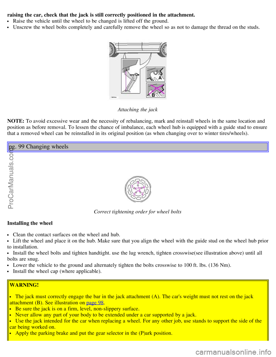
raising the car, check that the jack is still correctly positioned in the attachment.
Raise the vehicle until the wheel to be changed is lifted off the ground.
Unscrew the wheel bolts completely and carefully remove the wheel so as not to damage the thread on the studs.
Attaching the jack
NOTE: To avoid excessive wear and the necessity of rebalancing, mark and reinstall wheels in the same location and
position as before removal. To lessen the chance of imbalance, each wheel hub is equipped with a guide stud to ensure
that a removed wheel can be reinstalled in its original position (as when changing over to winter tires/wheels).
pg. 99 Changing wheels
Correct tightening order for wheel bolts
Installing the wheel
Clean the contact surfaces on the wheel and hub.
Lift the wheel and place it on the hub. Make sure that you align the wheel with the guide stud on the wheel hub prior
to installation.
Install the wheel bolts and tighten handtight. use the lug wrench, tighten crosswise(see illustration above) until all
bolts are snug.
Lower the vehicle to the ground and alternately tighten the bolts crosswise to 100 ft. lbs. (136 Nm).
Install the wheel cap (where applicable).
WARNING!
The jack must correctly engage the bar in the jack attachment (A). The car's weight must not rest on the jack
attachment (B). See illustration on page 98
.
Be sure the jack is on a firm, level, non-slippery surface.
Never allow any part of your body to be extended under a car supported by a jack.
Use the jack intended for the car when replacing a wheel. For any other job, use stands to support the side of the
car being worked on.
Apply the parking brake and put the gear selector in the (P)ark position.
ProCarManuals.com
Page 68 of 110
Block the wheels standing on the ground, use rigid wooden blocks or large stones.
The jack should be kept well-greased.
CAUTION:
The car must not be driven with wheels of different dimensions or with a spare tire other than the one that came
with the car. The use of different size wheels can seriously damage your car's transmission.
Correct tightening torque on wheel bolts must be observed. The wheel bolts should never be greased or lubricated.
The extended, chromed wheel bolts must not be used with steel rims, as they make it impossible to fit the hub caps.
pg. 100
This page intentionally left blank.
Contents | Top of Page
ProCarManuals.com
Page 72 of 110

Fuse box in the passenger compartment
This fuse box is located at the far left side of the instrument panel. Extra fuses and the fuse removal tool are also stored
here. When replacing a blown fuse, be sure to replace it with a new one of the same color and amperage (written on
the fuse).
Location Amperage
1 Low beam headlights 15A
2 High beam headlights 20A
3 Power driver's seat 30A
4 Power passenger's seat 30A
5 Speed -dependent power steering, vacuum pump 15A
6 -
7 Heated seat - front left (option) 15A
8 Heated seat - front right (option) 15A
9 ABS/STC/DSTC 5A
10 Daytime running lights 10A
11 Daytime running lights 10A
12 Headlight wipers (certain models) 15A
13 Electric socket 12 V 15A
14 Power passenger's seat 5A
15 Audio system, VNS 5A
16 Audio system 20A
17 Audio amplifier 30A
18 Front fog lights 15A
19 VNS display 10A
20 -
21 Automatic transmission, shiftlock, extended D2 feed 10A
22 Direction indicators 20A
23 Headlight switch module, climate control system, onboard diagnostic connector, steering wheel
lever modules 5A
24 Relay extended D1 feed: climate control system, power driver's seat, driver's info 10A
25 Ignition switch, relay starter motor, SRS, engine control module 10A
26 Climate control system blower 30A
27 -
28 Electronic module - courtesy lighting 10A
29 -
30 Left front/rear parking lights 7.5A
31 Right front/rear parking lights, license plate lights 7.5A
32 Central electrical module, vanity mirror lighting, power steering, glove compartment light,
interior courtesy lighting 10A
33 Fuel pump 15A
34 Power moonroof 15A
35 Central locking system, power windows - left door mirror 25A
36 Central locking system, power windows - right door mirror 25A
37 Rear power windows 30A
ProCarManuals.com
Page 81 of 110
7 Child safety latch label
* The Vehicle Identification Number (VIN) should always be quoted in all correspondence concerning your vehicle
with the retailer and when ordering parts.
All specifications are subject to change without prior notice.
pg. 131 Dimensions and weights
DimensionsLength 189.8 in. (482 cm)
Width 72.1 in. (183 cm)
Height 57.2 in. (145 cm)
Wheelbase 109.9 in. (279 cm)
Track, front 62.3 in. (158 cm)
Track, rear 61.4 in. (156 cm)
Turning circle (between curbs) 35.8 - 39 ft. (10.9 - 12 m)
Cargo capacity - trunk 14.2 cu. ft. (0.4 m
3)
Weights USACanada
Gross vehicle weight (GVW)
6 cyl. 4608 lbs2090 kg
6 cyl. turbo 4670 lbs2120 kg
Capacity weight *
6 cyl. 890 lbs400 kg
6 cyl. turbo 890 lbs400 kg
Curb weight
6 cyl. 3570-3600 Ibs1620-1640 kg
ProCarManuals.com
Page 84 of 110

Fuel system
The engine is equipped with a multiport fuel injection system.
Distributor ignition system
Firing order: 15-3-6-2-4
Distributor ignition setting: Not adjustable
Spark plugs: B 6284 T: P/N 271367-4 (or equivalent)
B 6294 S: P/N 272371-8 (or equivalent)
Spark plug gap: 0.028-0.032" (0.7-0.8 mm)
Tightening torque: 18.4 ft. lbs. (25 Nm)
WARNING!
The distributor ignition system operates at very high voltages. Special safety precautions must be followed to
prevent injury. Always turn the ignition off when:
Replacing distributor ignition components e.g. plugs, coil, etc.
Do not touch any part of the distributor ignition system while the engine is running. This may result in unintended
movements and body injury.
Front suspension
Spring strut suspension with integrated shock absorbers and control arms linked to the support frame. Power-assisted
rack and pinion steering. Safety type steering column.
The alignment specifications apply to an unladen car but include fuel, coolant and spare wheel.
Toe-in measured on the wheel rims: 2.3 mm +/ 0.8 mm
Toe-in measured on tire sides: 2.8 +/ 0.9 mm
Rear suspension
Individual rear wheel suspension with longitudinal support arms, double link arms and track rods.
Toe-in measured on the tire sides: 1.9 mm +/ 1.9 mm
Vehicle loading
The tires on your Volvo should perform to specifications at all normal loads when inflated as recommended on the tire
information label. The label is located on the inside of the fuel filler door and lists vehicle design limits. Do not load
your car beyond the load limits indicated.
WARNING!
Improperly inflated tires will reduce tire life, adversely affect vehicle handling and can possibly lead to failure
resulting in loss of vehicle control without prior warning.
All specifications are subject to change without prior notice.
pg. 135 Electrical system
Bulbs Bulb US no.Power Socket
Headlights
ProCarManuals.com
Page 89 of 110
6. Selector knob:
Radio
Internal CD changer
CD
Station scan - press
TV (option on certain models)
External CD changer (option)
7. Radio - Station seek up/down
CD - Selecting next/previous track
8. Radio - Manual station selection
CD - Fast forward/backward
9. CD eject
10. Dolby Pro Logic - switching on
11. 2 channel stereo
12 3 channel stereo
13. CD slot
14. CD random play
15. Program type
16. News
17. Traffic information
18. Automatic presetting of radio stations
19. Display
pg. 140 Audio systems HU-611/HU-801
Switch on/off
Press the knob to switch on or turn off the radio.
Volume control
Turn the knob clockwise to increase volume. Volume control is electronic and does not have an end stop. If you have
a key pad in the steering wheel, increase or decrease the volume with the + or- buttons.
Bass
Adjust the bass by pressing the button to extend the control and turning it to the left (less bass) or to the right (more
ProCarManuals.com
Page 91 of 110

A - Setting station
Press the left side of the button to select lower frequencies and the right side for higher frequencies. Set frequencies are
displayed.
B - Station seek up/down
Press the left side (lower frequency) or right side (higher frequency) of the button to start the seek function. The radio
seeks the next audible station and tunes it in. Repeat the procedure to continue the seek function.
Audio system controls on the steering wheel
Station seek up/down
If you have a key pad in the steering wheel press the right or left arrow to switch between preset stations.
Scan function
Press the SCAN button (HU-611) or the SOURCE button (HU-801) to start the station scan function. When a station
is found, scanning stops for several seconds, after which scanning will continue.
Press the SCAN or SOURCE button when a station has been found if you would like to listen to that station and to
discontinue the scan function.
pg. 142 Audio systems HU-611/HU-801 - radio
A - Automatic station preset
This function seeks and stores up to 10 strong AM or FM stations in a separate memory. This function is especially
useful in areas where you are not familiar with the radio stations.
ProCarManuals.com
Page 99 of 110

2 0 0 4
VOLVO S80
Index
pg. 157 Index
A
ABS..........17
ABS - warning light..........27
Accessory lights..........29
Active chassis system (Four-C)..........78
Adjusting the steering wheel..........36
Advanced User Mode (AUM) - radio..........145
Air conditioning..........45- 49
Air filter - engine..........119
Air vents..........44
Airbag (SIPS)..........8
Airbag (SRS)..........4
Alarm..........65, 66
Alarm - "panic" function..........65
ALR/ELR..........14
Anti-lock Brake System (ABS)..........17
Anti-lock Brake System - warning light..........27
Antifreeze..........89, 118
Approach lighting..........60
Ashtrays..........38
Audio systems..........137
cassette deck..........148
CD player..........146
HU -611 - overview..........138
HU -801 - overview..........139
radio..........142
specifications..........151
AUM (Advanced User Mode) - radio..........145
Automatic car washing..........115
Automatic Locking Retractor (ALR)..........14
Automatic transmission
ProCarManuals.com