2004 SUBARU FORESTER sensor
[x] Cancel search: sensorPage 2702 of 2870

4AT(H4DOTC)-126
AUTOMATIC TRANSMISSION (DIAGNOSTIC)
Symptom Related Diagnostic
15.Symptom Related Diagnostic
A: INSPECTION
Symptom Problem parts
Starter does not rotate when select lever is in “P” or “N” range,
starter rotates when select lever is in “R”, “D”, “3” or “2” range. Inhibitor switch
Select cable
Select lever
Starter motor and harness
Abnormal noise when select lever is in “P” or “N” range. Strainer
Transfer duty solenoid
Oil pump
Drive plate
ATF level too high or too low
Hissing noise occurs during standing start. Strainer
ATF level too high or too low
Noise occurs while driving in “D1”. Final gear
Planetary gear
Reduction gear
Differential gear oil level too high or too low Noise occurs while driving in “D2”.
Noise occurs while driving in “D3”. Final gear
Low & reverse brake
Reduction gear
Differential gear oil level too high or too low
Noise occurs while driving in “D4”. Final gear
Low & reverse brake
Planetary gear
Reduction gear
Differential gear oil level too high or too low
Engine stalls while shifting from “1” range to another. Control valve
Lock-up damper
Engine performance
Input shaft
Vehicle moves when select lever is in “N” range. Select cable
Inhibitor switch
TCM
Low clutch
Shock occurs when select lever is shifted from “N” to “D” range. Accelerator pedal position sensor
ATF temperature sensor
Line pressure linear solenoid
Low clutch duty solenoid
Low clutch
TCM
Harness
Control valve
ATF deterioration
Excessive time lag occurs when select lever is shifted from “N”
to “D” range. Control valve
Low clutch
Line pressure duty solenoid
Seal ring
Front gasket of transmission case
Shock occurs when select lever is shifted from “N” to “R” range. Accelerator pedal position sensor
ATF temperature sensor
Line pressure linear solenoid
TCM
Harness
Control valve
ATF deterioration
Page 2704 of 2870

4AT(H4DOTC)-128
AUTOMATIC TRANSMISSION (DIAGNOSTIC)
Symptom Related Diagnostic
No shift occurs from 1st to 2nd gear.TCM
Rear vehicle speed sensor
Front vehicle speed sensor
Throttle position sensor
Control valve
2-4 brake
No shift occurs from 2nd to 3rd gear.TCM
Control valve
High clutch
No shift occurs from 3rd to 4th gear.TCM
ATF temperature sensor
Control valve
2-4 brake
Engine brake is not effected when select lever is in “3” range. Inhibitor switch
TCM
Throttle position sensor
Control valve
Engine brake is not effected when select lever is in “3” or “2”
range.Control valve
Engine brake is not effected when select lever is in “1” range. Control valve
Low & reverse brake
Shift characteristics are erroneous. Inhibitor switch
TCM
Front vehicle speed sensor
Rear vehicle speed sensor
Throttle position sensor
Control valve
Ground earth
No lock-up occurs.TCM
Torque converter turbine speed sensor
Throttle position sensor
ATF temperature sensor
Control valve
Lock-up facing
Engine speed signal
Parking brake is not effected. Select cable
Select lever
Parking mechanism Shift lever cannot be moved or is hard to move from “P” range.
ATF spurts out. ATF level too high
Differential oil spurts out. Differential gear oil too high
Differential oil level changes excessively. Seal pipe
Double oil seal
Odor is produced from ATF supply pipe.High clutch
2-4 brake
Low & reverse clutch
Reverse clutch
Lock-up facing
ATF deterioration
Shock occurs from 1st to 2nd gear.TCM
Torque converter turbine speed sensor
Accelerator pedal position sensor
2-4 brake duty solenoid
ATF temperature sensor
Line pressure linear solenoid
Control valve
2-4 brake
ATF deterioration
Engine performance
Low & reverse duty solenoid Symptom Problem parts
Page 2705 of 2870

4AT(H4DOTC)-129
AUTOMATIC TRANSMISSION (DIAGNOSTIC)
Symptom Related Diagnostic
Slippage occurs from 1st to 2nd gear.TCM
Accelerator pedal position sensor
2-4 brake duty solenoid
ATF temperature sensor
Line pressure linear solenoid
Control valve
2-4 brake
Shock occurs from 2nd to 3rd gear.TCM
Torque converter turbine speed sensor
Accelerator pedal position sensor
2-4 brake duty solenoid
ATF temperature sensor
Line pressure linear solenoid
Low & reverse duty solenoid
Control valve
High clutch
2-4 brake
ATF deterioration
Engine performance
High clutch duty solenoid
Slippage occurs from 2nd to 3rd gear.TCM
Accelerator pedal position sensor
2-4 brake duty solenoid
ATF temperature sensor
Line pressure linear solenoid
Control valve
High clutch
2-4 brake
Low & reverse duty solenoid
Shock occurs from 3rd to 4th gear.TCM
Torque converter turbine speed sensor
Accelerator pedal position sensor
2-4 brake duty solenoid
ATF temperature sensor
Line pressure linear solenoid
Control valve
Low clutch duty solenoid
2-4 brake
ATF deterioration
Engine performance
Slippage occurs from 3rd to 4th gear.TCM
Accelerator pedal position sensor
2-4 brake duty solenoid
ATF temperature sensor
Line pressure linear solenoid
Control valve
2-4 brake
Shock occurs when select lever is shifted from “3” to “2” range.TCM
Torque converter turbine speed sensor
Accelerator pedal position sensor
ATF temperature sensor
Line pressure linear solenoid
Control valve
2-4 brake duty solenoid
2-4 brake
ATF deterioration
High clutch duty solenoid Symptom Problem parts
Page 2706 of 2870

4AT(H4DOTC)-130
AUTOMATIC TRANSMISSION (DIAGNOSTIC)
Symptom Related Diagnostic
Shock occurs when select lever is shifted from “D” to “1” range.TCM
Torque converter turbine speed sensor
Accelerator pedal position sensor
ATF temperature sensor
Line pressure linear solenoid
Control valve
ATF deterioration
Low & reverse brake duty solenoid
Low & reverse clutch solenoid
Shock occurs when select lever is shifted from “2” to “1” range.TCM
Torque converter turbine speed sensor
Accelerator pedal position sensor
ATF temperature sensor
Line pressure linear solenoid
Control valve
Low & reverse clutch
ATF deterioration
2-4 brake duty solenoid
Low & reverse brake duty solenoid
Shock occurs when accelerator pedal is released at medium
speeds.TCM
Accelerator pedal position sensor
ATF temperature sensor
Line pressure linear solenoid
Control valve
Lock-up damper
Engine performance
Vibration occurs during straight-forward operation.TCM
Lock-up duty solenoid
Lock-up facing
Lock-up damper
HOLD switch
Vibration occurs during turns (tight corner “braking” phenome-
non).TCM
Front vehicle speed sensor
Rear vehicle speed sensor
Accelerator pedal position sensor
ATF temperature sensor
Transfer clutch
Transfer valve
Transfer duty solenoid
ATF deterioration
Harness
HOLD switch
Front wheel slippage occurs during standing starts.TCM
Front vehicle speed sensor
Accelerator pedal position sensor
ATF temperature sensor
Control valve
Transfer clutch
Transfer valve
Transfer pipe
Transfer duty solenoid
Vehicle is not set in FWD mode.TCM
Transfer clutch
Transfer valve
Transfer duty solenoid
Select lever is hard to move. Select cable
Select lever
Detente spring
Manual plate Symptom Problem parts
Page 2713 of 2870

MANUAL TRANSMISSION AND
DIFFERENTIAL
5MT
Page
1. General Description ....................................................................................2
2. Transmission Gear Oil ..............................................................................31
3. Manual Transmission Assembly ...............................................................32
4. Transmission Mounting System ................................................................39
5. Oil Seal......................................................................................................41
6. Differential Side Retainer Oil Seal.............................................................42
7. Switches and Harness ..............................................................................43
8. Vehicle Speed Sensor...............................................................................46
9. Preparation for Overhaul ...........................................................................47
10. Oil Pump ...................................................................................................48
11. Transfer Case and Extension Case Assembly..........................................50
12. Transfer Drive Gear ..................................................................................54
13. Transfer Driven Gear ................................................................................56
14. Center Differential .....................................................................................58
15. Reverse Check Sleeve..............................................................................59
16. Transmission Case ...................................................................................62
17. Main Shaft Assembly For Single-Range ...................................................69
18. Main Shaft Assembly For Dual-Range ......................................................77
19. Input Shaft Assembly ................................................................................83
20. Drive Pinion Shaft Assembly .....................................................................87
21. Front Differential Assembly .......................................................................96
22. Speedometer Gear..................................................................................103
23. Reverse Idler Gear ..................................................................................104
24. Shifter Fork and Rod ...............................................................................106
25. Counter Gear ..........................................................................................109
26. General Diagnostic..................................................................................111
Page 2744 of 2870

5MT-32
MANUAL TRANSMISSION AND DIFFERENTIAL
Manual Transmission Assembly
3. Manual Transmission As-
sembly
A: REMOVAL
1) Set the vehicle on a lift.
2) Disconnect the ground cable from battery.
3) Drain the transmission gear oil completely.
Oil.>
4) Open the front hood fully, and support with stay.
5) Remove the air intake duct and air cleaner case.
(Non-turbo model)
6) Remove the air cleaner case stay. (Non-turbo
model)
7) Remove the intercooler. (Turbo model)
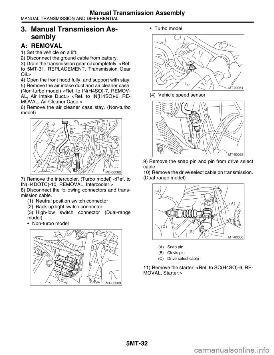
8) Disconnect the following connectors and trans-
mission cable.
(1) Neutral position switch connector
(2) Back-up light switch connector
(3) High-low switch connector (Dual-range
model)
Non-turbo model Turbo model
(4) Vehicle speed sensor
9) Remove the snap pin and pin from drive select
cable.
10) Remove the drive select cable on transmission.
(Dual-range model)
11) Remove the starter.
ME-00062
MT-00063
(A) Snap pin
(B) Clevis pin
(C) Drive select cable
MT-00064
MT-00065
MT-00066
(A)
(B)
(C)
Page 2750 of 2870

5MT-38
MANUAL TRANSMISSION AND DIFFERENTIAL
Manual Transmission Assembly
24) Push clutch release lever to fit bearing into
clutch cover.
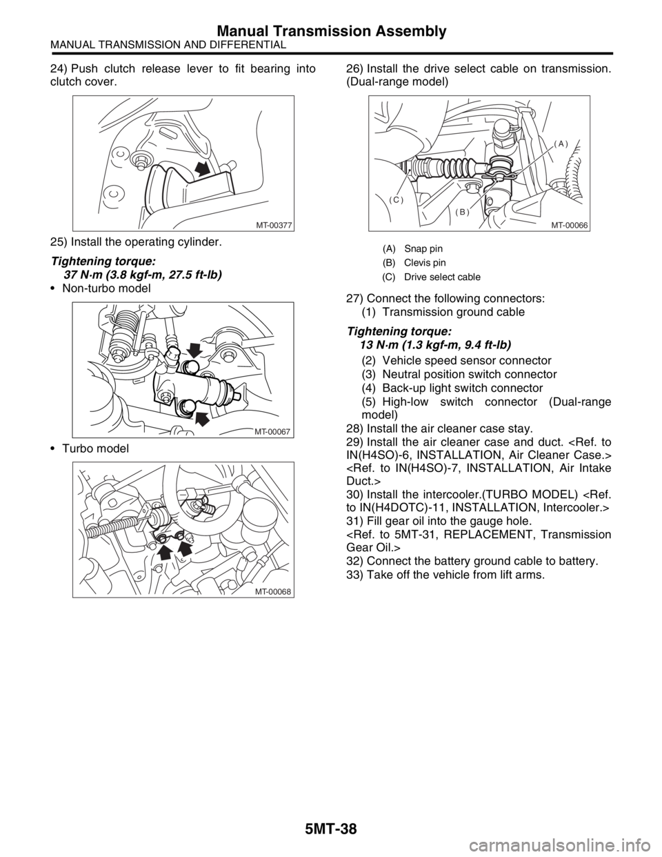
25) Install the operating cylinder.
Tightening torque:
37 N·m (3.8 kgf-m, 27.5 ft-lb)
Non-turbo model
Turbo model26) Install the drive select cable on transmission.
(Dual-range model)
27) Connect the following connectors:
(1) Transmission ground cable
Tightening torque:
13 N·m (1.3 kgf-m, 9.4 ft-lb)
(2) Vehicle speed sensor connector
(3) Neutral position switch connector
(4) Back-up light switch connector
(5) High-low switch connector (Dual-range
model)
28) Install the air cleaner case stay.
29) Install the air cleaner case and duct.
30) Install the intercooler.(TURBO MODEL)
31) Fill gear oil into the gauge hole.
32) Connect the battery ground cable to battery.
33) Take off the vehicle from lift arms.
MT-00377
MT-00067
MT-00068
(A) Snap pin
(B) Clevis pin
(C) Drive select cable
MT-00066
(A)
(B)
(C)
Page 2758 of 2870

5MT-46
MANUAL TRANSMISSION AND DIFFERENTIAL
Vehicle Speed Sensor
8. Vehicle Speed Sensor
A: REMOVAL
1) Disconnect the ground cable from battery.
2) Lift-up the vehicle.
3) Remove the front, center and rear exhaust pipe
and muffler.
4) Disconnect the connector from vehicle speed
sensor.
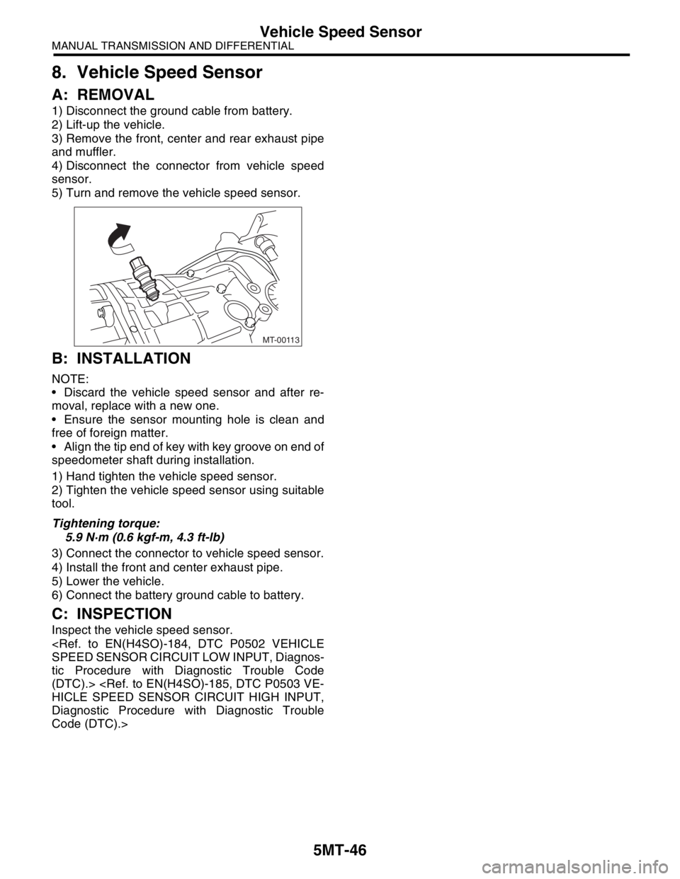
5) Turn and remove the vehicle speed sensor.
B: INSTALLATION
NOTE:
Discard the vehicle speed sensor and after re-
moval, replace with a new one.
Ensure the sensor mounting hole is clean and
free of foreign matter.
Align the tip end of key with key groove on end of
speedometer shaft during installation.
1) Hand tighten the vehicle speed sensor.
2) Tighten the vehicle speed sensor using suitable
tool.
Tightening torque:
5.9 N·m (0.6 kgf-m, 4.3 ft-lb)
3) Connect the connector to vehicle speed sensor.
4) Install the front and center exhaust pipe.
5) Lower the vehicle.
6) Connect the battery ground cable to battery.
C: INSPECTION
Inspect the vehicle speed sensor.
tic Procedure with Diagnostic Trouble Code
(DTC).>
Diagnostic Procedure with Diagnostic Trouble
Code (DTC).>
MT-00113