Page 1021 of 2870

CO(H4SO)-38
COOLING
Radiator Main Fan and Fan Motor
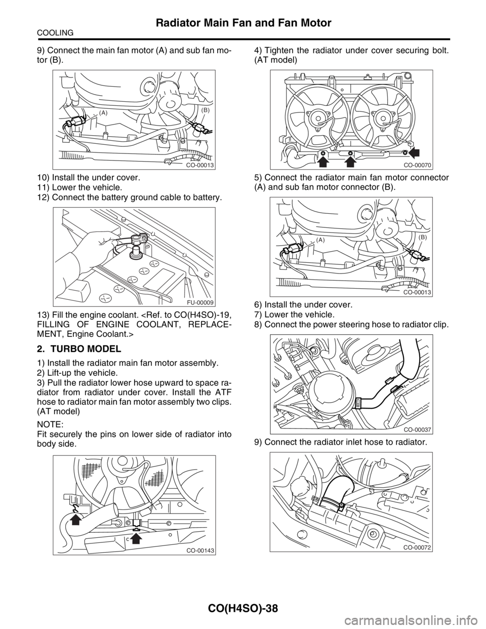
9) Connect the main fan motor (A) and sub fan mo-
tor (B).
10) Install the under cover.
11) Lower the vehicle.
12) Connect the battery ground cable to battery.
13) Fill the engine coolant.
FILLING OF ENGINE COOLANT, REPLACE-
MENT, Engine Coolant.>
2. TURBO MODEL
1) Install the radiator main fan motor assembly.
2) Lift-up the vehicle.
3) Pull the radiator lower hose upward to space ra-
diator from radiator under cover. Install the ATF
hose to radiator main fan motor assembly two clips.
(AT model)
NOTE:
Fit securely the pins on lower side of radiator into
body side.4) Tighten the radiator under cover securing bolt.
(AT model)
5) Connect the radiator main fan motor connector
(A) and sub fan motor connector (B).
6) Install the under cover.
7) Lower the vehicle.
8) Connect the power steering hose to radiator clip.
9) Connect the radiator inlet hose to radiator.
CO-00013
(A)(B)
FU-00009
CO-00143
CO-00070
CO-00013
(A)(B)
CO-00037
CO-00072
Page 1022 of 2870

CO(H4SO)-39
COOLING
Radiator Main Fan and Fan Motor
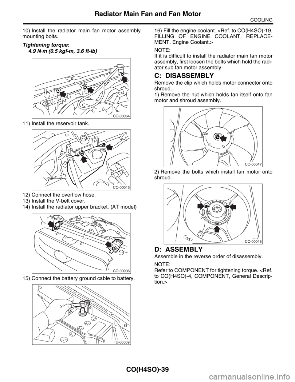
10) Install the radiator main fan motor assembly
mounting bolts.
Tightening torque:
4.9 N
⋅m (0.5 kgf-m, 3.6 ft-lb)
11) Install the reservoir tank.
12) Connect the overflow hose.
13) Install the V-belt cover.
14) Install the radiator upper bracket. (AT model)
15) Connect the battery ground cable to battery.16) Fill the engine coolant.
FILLING OF ENGINE COOLANT, REPLACE-
MENT, Engine Coolant.>
NOTE:
If it is difficult to install the radiator main fan motor
assembly, first loosen the bolts which hold the radi-
ator sub fan motor assembly.
C: DISASSEMBLY
Remove the clip which holds motor connector onto
shroud.
1) Remove the nut which holds fan itself onto fan
motor and shroud assembly.
2) Remove the bolts which install fan motor onto
shroud.
D: ASSEMBLY
Assemble in the reverse order of disassembly.
NOTE:
Refer to COMPONENT for tightening torque.
to CO(H4SO)-4, COMPONENT, General Descrip-
tion.>
CO-00064
CO-00015
CO-00036
FU-00009
CO-00047
CO-00048
Page 1024 of 2870
CO(H4SO)-41
COOLING
Reservoir Tank
10.Reservoir Tank
A: REMOVAL
1) Disconnect the over flow hose from radiator filler
neck position.
2) Remove the bolts which install reservoir tank
onto radiator main fan shroud.
3) Remove the reservoir tank.
B: INSTALLATION
Install in the reverse order of removal.
NOTE:
Refer to COMPONENT for tightening torque.
to CO(H4SO)-4, COMPONENT, General Descrip-
tion.>
C: INSPECTION
Make sure the engine coolant level is between full
and low.
CO-00015
Page 1025 of 2870
CO(H4SO)-42
COOLING
Coolant Filler Tank
11.Coolant Filler Tank
A: REMOVAL
WARNING:
The radiator is pressurized. Wait until the en-
gine cools down before working on the radia-
tor.
1) Drain the coolant about 3.02 (3.2 US qt, 2.6 Imp
qt).
GINE COOLANT, REPLACEMENT, Engine Cool-
ant.>
2) Remove the air cleaner upper cover and air in-
take boot.
Cleaner.>
3) Remove the air cleaner element.
4) Disconnect the engine coolant hoses from cool-
ant filler tank.
5) Remove the bolts and nut which install coolant
filler tank.
6) Disconnect the engine coolant hose which con-
nects under side of coolant filler tank.
7) Remove the coolant filler tank.
B: INSTALLATION
1) Install in the reverse order of removal.
Tightening torque:
T1: 19 N
⋅m (1.9 kgf-m, 13.7 ft-lb)
T2: 21 N
⋅m (2.1 kgf-m, 15.2 ft-lb)
2) Fill engine coolant.
ING OF ENGINE COOLANT, REPLACEMENT,
Engine Coolant.>
CO-00051
CO-00052
T2
T1
CO-00053
Page 1026 of 2870

CO(H4SO)-43
COOLING
Engine Cooling System Trouble in General
12.Engine Cooling System Trouble in General
A: INSPECTION
Trouble Possible cause Corrective action
Over-heatinga. Insufficient engine coolantReplenish the engine coolant, inspect for leakage, and
repair.
b. Loose timing belt Repair or replace the timing belt tensioner.
c. Oil on drive belt Replace.
d. Malfunction of thermostat Replace.
e. Malfunction of water pump Replace.
f. Clogged engine coolant passage Clean.
g. Improper ignition timingInspect and repair the ignition control system.
nostics Procedure.>
h. Clogged or leaking radiator Clean or repair, or replace.
i. Improper engine oil in engine coolant Replace the engine coolant.
j. Air/fuel mixture ratio too leanInspect and repair the fuel injection system.
nostics Procedure.>
k. Excessive back pressure in exhaust system Clean or replace.
l. Insufficient clearance between piston and cylinder Adjust or replace.
m. Slipping clutch Repair or replace.
n. Dragging brake Adjust.
o. Defective thermostat Replace.
p. Malfunction of radiator fanInspect the radiator fan relay, engine coolant tempera-
ture sensor or radiator motor and replace there.
Over-coolinga. Atmospheric temperature extremely low Partly cover the radiator front area.
b. Defective thermostat Replace.
Engine coolant
leaks.a. Loosened or damaged connecting units on hoses Repair or replace.
b. Leakage from water pump Replace.
c. Leakage from water pipe Repair or replace.
d. Leakage around cylinder head gasket Retighten the cylinder head bolts or replace gasket.
e. Damaged or cracked cylinder head and crankcase Repair or replace.
f. Damaged or cracked thermostat case Repair or replace.
g. Leakage from radiator Repair or replace.
Noisea. Defective drive belt Replace.
b. Defective radiator fan Replace.
c. Defective water pump bearing Replace the water pump.
d. Defective water pump mechanical seal Replace the water pump.
Page 1049 of 2870
LU(H4SO)-21
LUBRICATION
Engine Oil Cooler
7. Engine Oil Cooler
A: REMOVAL
NOTE:
Engine oil cooler is equipped with turbo model only.
1) Lift-up the vehicle.
2) Remove the under cover.
3) Drain the engine oil. Set a container under the
vehicle, and remove the drain plug from oil pan.
4) Drain the engine coolant.
5) Remove the water by-pass pipe between oil
cooler and water pump.
6) Remove the engine oil filter.
23, REMOVAL, Engine Oil Filter.>
7) Remove the connector and remove oil cooler.8) Remove the adapters (1) and (2).
(A) Gasket
(B) Drain plug
LU-00039
(B)(A)
LU-00040
(A) Adapter (1)
(B) Adapter connector
(C) Adapter (2)
(D) Oil cooler
(E) Oil cooler connector
LU-00041
(A)
(B)
(C)
(D)
(E)
Page 1050 of 2870
LU(H4SO)-22
LUBRICATION
Engine Oil Cooler
B: INSTALLATION
NOTE:
Engine oil cooler is equipped with turbo model only.
1) Install in the reverse order of removal.
2) Contact the knock pin (A) of adapter (1) to cylin-
der block rib (B) to install adapter (1).
3) Install the adapter (2).
4) Contact the engine oil cooler stopper (A) to
adapter (2) rib (B) to install engine oil cooler.
Tightening torque:
T1: 6.4 N
⋅m (0.7 kgf-m, 5.1 ft-lb)
T2: 44 N
⋅m (4.5 kgf-m, 33 ft-lb)
T3: 54 N
⋅m (5.5 kgf-m, 40 ft-lb)NOTE:
Always use a new O-ring.
C: INSPECTION
1) Check that the coolant passages are not
clogged using air blow method.
2) Check the mating surfaces of cylinder block, O-
ring groove and oil filter for damage.
LU-00042
(A)
(B)
LU-00043
(B)(A)
(A) Adapter (1)
(B) Adapter connector
(C) Adapter (2)
(D) Oil cooler
(E) Oil cooler connector
LU-00044
(A)
(B)
(C)
(D)
(E)
T1
T2
T3
Page 1105 of 2870

EN(H4SO)-7
ENGINE (DIAGNOSTIC)
General Description
The antenna feeder must be placed as far
apart as possible from the ECM and MFI har-
ness.
Carefully adjust the antenna for correct
matching.
When mounting a large power type radio, pay
special attention to the three items above men-
tioned.
Incorrect installation of the radio may affect
the operation of the ECM.
13) Before disconnecting the fuel hose, disconnect
the fuel pump connector and crank the engine for
more than five seconds to release pressure in the
fuel system. If engine starts during this operation,
run it until it stops.
14) Problems in the electronic-controlled automatic
transmission may be caused by failure of the en-
gine, the electronic control system, the transmis-
sion proper, or by a combination of these. These
three causes must be distinguished clearly when
performing diagnostics.
15) Diagnostics should be conducted by rotating
with simple, easy operations and proceeding to
complicated, difficult operations. The most impor-
tant thing in diagnostics is to understand the cus-
tomer’s complaint, and distinguish between the
three causes.
16) In AT models, do not continue the stall for more
than five seconds. (from closed throttle, fully open
throttle to stall engine speed.)
17) On the model with ABS, when performing driv-
ing test in jacked-up or lifted-up position, some-
times the warning light may be lit, but this is not a
malfunction of the system. The reason for this is the
speed difference between the front and rear
wheels. After diagnosis of engine control system,
perform the ABS memory clearance procedure of
self-diagnosis function.
B: INSPECTION
Before performing diagnostics, check the following
items which might affect engine problems:
1. BATTERY
1) Measure battery voltage and specific gravity of
electrolyte.
Standard voltage: 12 V
Specific gravity: Above 1.260
2) Check the condition of the main and other fuses,
and harnesses and connectors. Also check for
proper grounding.
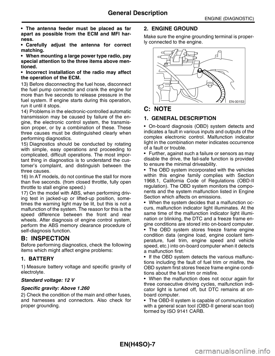
2. ENGINE GROUND
Make sure the engine grounding terminal is proper-
ly connected to the engine.
C: NOTE
1. GENERAL DESCRIPTION
On-board diagnosis (OBD) system detects and
indicates a fault in various inputs and outputs of the
complex electronic control. Malfunction indicator
light in the combination meter indicates occurrence
of a fault or trouble.
Further, against such a failure or sensors as may
disable the drive, the fail-safe function is provided
to ensure the minimal driveability.
The OBD system incorporated with the vehicles
within this engine family complies with Section
1968.1, California Code of Regulations (OBD-II
regulation). The OBD system monitors the compo-
nents and the system malfunction listed in Engine
Section which affects on emissions.
When the system decides that a malfunction oc-
curs, malfunction indicator light illuminates. At the
same time of the malfunction indicator light illumi-
nation or blinking, the DTC and a freeze frame en-
gine conditions are stored into on-board computer.
The OBD system stores freeze frame engine
condition data (engine load, engine coolant tem-
perature, fuel trim, engine speed and vehicle
speed, etc.) into on-board computer when it detects
a malfunction first.
If the OBD system detects the various malfunc-
tions including the fault of fuel trim or misfire, the
OBD system first stores freeze frame engine condi-
tions about the fuel trim or misfire.
When the malfunction does not occur again for
three consecutive driving cycles, malfunction indi-
cator light is turned off, but DTC remains at on-
board computer.
The OBD-II system is capable of communication
with a general scan tool (OBD-II general scan tool)
formed by ISO 9141 CARB.
EN-00153