Page 1765 of 2870

EN(H4DOTC)-132
ENGINE (DIAGNOSTIC)
Diagnostic Procedure with Diagnostic Trouble Code (DTC)
W: DTC P0129 BAROMETRIC PRESSURE TOO LOW
DTC DETECTING CONDITION:
Two consecutive driving cycles with fault
CAUTION:
After repair or replacement of faulty parts, conduct Clear Memory Mode
ERATION, Clear Memory Mode.> and Inspection Mode .
Step Check Yes No
1 CHECK ANY OTHER DTC ON DISPLAY.Is any other DTC displayed? Inspect the rele-
vant DTC using
“List of Diagnostic
Trouble Code
(DTC)”.
EN(H4DOTC)-74,
List of Diagnostic
Trouble Code
(DTC).>
N
OTE:
In this case, it is
not necessary to
inspect DTC
P0125.Go to step 2.
2 CHECK ENGINE COOLING SYSTEM.
N
OTE:
Check the following items:
Thermostat open stuck
Coolant level
Coolant freeze
Tire diameterIs there a fault in engine cool-
ing system?Replace the ther-
mostat.
CO(H4SO)-26,
Thermostat.>Replace the
engine coolant
temperature sen-
sor.
FU(H4DOTC)-29,
Engine Coolant
Temperature Sen-
sor.>
Step Check Yes No
1 CHECK ANY OTHER DTC ON DISPLAY.Is any other DTC displayed? Inspect the rele-
vant DTC using
“List of Diagnostic
Trouble Code
(DTC)”.
EN(H4DOTC)-74,
List of Diagnostic
Trouble Code
(DTC).>
N
OTE:
It is not necessary
to inspect DTC
P0129.Replace the ECM.
FU(H4DOTC)-50,
Engine Control
Module (ECM).>
NOTE:
Atmospheric pres-
sure sensor is built
in ECM.
Page 2376 of 2870

4AT-63
AUTOMATIC TRANSMISSION
Control Valve Body
B: INSTALLATION
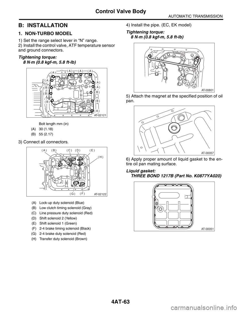
1. NON-TURBO MODEL
1) Set the range select lever in “N” range.
2) Install the control valve, ATF temperature sensor
and ground connectors.
Tightening torque:
8 N
⋅m (0.8 kgf-m, 5.8 ft-lb)
3) Connect all connectors.4) Install the pipe. (EC, EK model)
Tightening torque:
8 N
⋅m (0.8 kgf-m, 5.8 ft-lb)
5) Attach the magnet at the specified position of oil
pan.
6) Apply proper amount of liquid gasket to the en-
tire oil pan mating surface.
Liquid gasket:
THREE BOND 1217B (Part No. K0877YA020)
Bolt length mm (in)
(A) 30 (1.18)
(B) 55 (2.17)
(A) Lock-up duty solenoid (Blue)
(B) Low clutch timing solenoid (Gray)
(C) Line pressure duty solenoid (Red)
(D) Shift solenoid 2 (Yellow)
(E) Shift solenoid 1 (Green)
(F) 2-4 brake timing solenoid (Black)
(G) 2-4 brake duty solenoid (Red)
(H) Transfer duty solenoid (Brown)
AT-02121
(A)(A)(A)(A)
(A)(A)
(A)
(A)
(B)
(B)
(B)
(B)
(B)
AT-02122
(A) (B) (C) (D) (E)
(H)
(F)
(G)
AT-00801
AT-00057
AT-00051
Page 2385 of 2870

4AT-72
AUTOMATIC TRANSMISSION
Shift Solenoids, Duty Solenoids and ATF Temperature Sensor
2) Tighten the bolt and nut.
Tightening torque:
8 N
⋅m (0.8 kgf-m, 5.8 ft-lb)
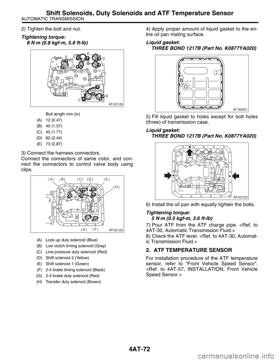
3) Connect the harness connectors.
Connect the connectors of same color, and con-
nect the connectors to control valve body using
clips.4) Apply proper amount of liquid gasket to the en-
tire oil pan mating surface.
Liquid gasket:
THREE BOND 1217B (Part No. K0877YA020)
5) Fill liquid gasket to holes except for bolt holes
(three) of transmission case.
Liquid gasket:
THREE BOND 1217B (Part No. K0877YA020)
6) Install the oil pan with equally tighten the bolts.
Tightening torque:
5 N
⋅m (0.5 kgf-m, 3.6 ft-lb)
7) Pour ATF from the ATF charge pipe.
4AT-30, Automatic Transmission Fluid.>
8) Check the ATF level.
ic Transmission Fluid.>
2. ATF TEMPERATURE SENSOR
For installation procedure of the ATF temperature
sensor, refer to “Front Vehicle Speed Sensor”.
Speed Sensor.>
Bolt length mm (in)
(A) 12 (0.47)
(B) 40 (1.57)
(C) 45 (1.77)
(D) 62 (2.44)
(E) 73 (2.87)
(A) Lock-up duty solenoid (Blue)
(B) Low clutch timing solenoid (Gray)
(C) Line pressure duty solenoid (Red)
(D) Shift solenoid 2 (Yellow)
(E) Shift solenoid 1 (Green)
(F) 2-4 brake timing solenoid (Black)
(G) 2-4 brake duty solenoid (Red)
(H) Transfer duty solenoid (Brown)
AT-02126
E
AD
EE
D
D
B
CC
AT-02122
(A) (B) (C) (D) (E)
(H)
(F)
(G)
AT-00051
AT-02123