Page 903 of 2870
ME(H4SO)-34
MECHANICAL
Engine Assembly
9. Engine Assembly
A: REMOVAL
1) Set the vehicle on lift arms.
2) Open the front hood fully, and then support with
the front hood stay.
3) Release the fuel pressure.
47, RELEASING OF FUEL PRESSURE, OPERA-
TION, Fuel.>
4) Disconnect the A/C pressure hoses from A/C
compressor.
5) Remove the fuel filler cap.
6) Disconnect the ground cable from battery.
7) Remove the air intake duct and air cleaner case.
Case.>
8) Remove the under cover.
9) Remove the radiator from vehicle.
CO(H4SO)-28, REMOVAL, Radiator.>
10) Remove the air cleaner case stay.
MT model
AT model11) Disconnect the following connectors and ca-
bles.
(1) Front oxygen (A/F) sensor connector
(2) Rear oxygen sensor connector
(3) Engine ground cable
FU-00009
ME-00204
ME-00205
EX-00029
EX-00030
ME-00206
Page 971 of 2870

EX(H4SO)-3
EXHAUST
General Description
(1) Front exhaust pipe upper cover
CTR(14) Muffler (28) Rear catalytic converter upper
cover
(15) Cushion rubber
(2) Front exhaust pipe lower cover
CTR(16) Rear exhaust pipe (29) Rear catalytic converter lower
cover
(17) Clamp
(3) Clamp (18) Center exhaust pipe upper cover (30) Rear catalytic converter
(4) Front exhaust pipe upper cover LH (19) Center exhaust pipe lower cover (31) Gasket
(5) Front exhaust pipe lower cover LH (20) Protector
(6) Front exhaust pipe (21) GasketTightening torque: N
⋅m (kgf-m, ft-lb)
(7) Front exhaust pipe lower cover RH (22) Front oxygen (A/F) sensorT1: 8 (0.8, 5.8)
(8) Front exhaust pipe upper cover
RH(23) Front catalytic converterT2: 13 (1.3, 9.4)
(24) Center exhaust pipeT3: 18 (1.8, 13.0)
(9) Gasket (25) Front catalytic converter lower
coverT4: 21 (2.1, 15.2)
(10) SpringT5: 30 (3.1, 22.4)
(11) Chamber (26) Front catalytic converter upper
coverT6: 35 (3.6, 26.0)
(12) GasketT7: 48 (4.9, 35.4)
(13) Self-locking nut (27) Rear oxygen sensor
Page 973 of 2870

EX(H4SO)-5
EXHAUST
General Description
(1) Front exhaust pipe upper cover
CTR(15) Rear exhaust upper cover (31) Front catalytic converter upper
cover
(16) Rear exhaust lower cover
(2) Front exhaust pipe lower cover
CTR(17) Rear catalytic lower converter
cover(32) Front oxygen (A/F) sensor
(33) Rear oxygen sensor
(3) Clamp (18) Clamp (34) Clamp
(4) Front exhaust pipe upper cover LH (19) Cushion rubber
(5) Front exhaust pipe lower cover LH (20) Rear exhaust pipeTightening torque: N
⋅m (kgf-m, ft-lb)
(6) Front exhaust pipe (21) GasketT1: 8 (0.8, 5.8)
(7) Front exhaust pipe lower cover RH (22) Self-locking nutT2: 13 (1.3, 9.4)
(8) Front exhaust pipe upper cover
RH(23) MufflerT3: 18 (1.8, 13.0)
(24) ProtectorT4: 21 (2.1, 15.2)
(9) Gasket (25) GasketT5: 30 (3.1, 22.4)
(10) Gasket (26) Front catalytic converterT6: 35 (3.6, 26.0)
(11) Spring (27) Center exhaust lower coverT7: 48 (4.9, 35.4)
(12) Chamber (28) Center exhaust upper cover
(13) Rear catalytic converter (29) Center exhaust pipe
(14) Rear catalytic converter upper
cover(30) Front catalytic converter lower
cover
Page 975 of 2870
EX(H4SO)-7
EXHAUST
Front Exhaust Pipe
2. Front Exhaust Pipe
A: REMOVAL
1) Disconnect the ground cable from battery.
2) Disconnect the front oxygen (A/F) sensor con-
nector.
3) Disconnect the rear oxygen sensor connector.4) Lift-up the vehicle.
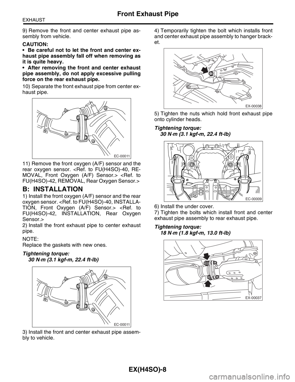
5) Separate the front and center exhaust pipe as-
sembly from rear exhaust pipe.
CAUTION:
Be careful, the exhaust pipe is hot.
6) Remove the under cover.
7) Remove the nuts which hold front exhaust pipe
onto cylinder heads.
8) Remove the bolt which installs front and center
exhaust pipe assembly to hanger bracket.
FU-00009
EX-00029
EX-00030
EX-00037
EC-00009
EX-00038
Page 976 of 2870

EX(H4SO)-8
EXHAUST
Front Exhaust Pipe
9) Remove the front and center exhaust pipe as-
sembly from vehicle.
CAUTION:
Be careful not to let the front and center ex-
haust pipe assembly fall off when removing as
it is quite heavy.
After removing the front and center exhaust
pipe assembly, do not apply excessive pulling
force on the rear exhaust pipe.
10) Separate the front exhaust pipe from center ex-
haust pipe.
11) Remove the front oxygen (A/F) sensor and the
rear oxygen sensor.
MOVAL, Front Oxygen (A/F) Sensor.>
FU(H4SO)-42, REMOVAL, Rear Oxygen Sensor.>
B: INSTALLATION
1) Install the front oxygen (A/F) sensor and the rear
oxygen sensor.
TION, Front Oxygen (A/F) Sensor.>
FU(H4SO)-42, INSTALLATION, Rear Oxygen
Sensor.>
2) Install the front exhaust pipe to center exhaust
pipe.
NOTE:
Replace the gaskets with new ones.
Tightening torque:
30 N
⋅m (3.1 kgf-m, 22.4 ft-lb)
3) Install the front and center exhaust pipe assem-
bly to vehicle.4) Temporarily tighten the bolt which installs front
and center exhaust pipe assembly to hanger brack-
et.
5) Tighten the nuts which hold front exhaust pipe
onto cylinder heads.
Tightening torque:
30 N
⋅m (3.1 kgf-m, 22.4 ft-lb)
6) Install the under cover.
7) Tighten the bolts which install front and center
exhaust pipe assembly to rear exhaust pipe.
Tightening torque:
18 N
⋅m (1.8 kgf-m, 13.0 ft-lb)
EC-00011
EC-00011
EX-00038
EC-00009
EX-00037
Page 977 of 2870
EX(H4SO)-9
EXHAUST
Front Exhaust Pipe
8) Tighten the bolt which holds front and center ex-
haust pipe assembly to hanger bracket.
Tightening torque:
35 N
⋅m (3.6 kgf-m, 26.0 ft-lb)
9) Lower the vehicle.
10) Connect the rear oxygen sensor connector.
11) Connect the front oxygen (A/F) sensor connec-
tor.
12) Connect the battery ground cable to battery.
C: INSPECTION
1) Make sure there are no exhaust leaks from con-
nections and welds.
2) Make sure there are no holes or rusting.
EX-00038
EX-00030
EX-00029
FU-00009
Page 1111 of 2870
EN(H4SO)-13
ENGINE (DIAGNOSTIC)
Electrical Component Location
EN-00162
(2)
(3) (1)
(4)
(1) Front oxygen (A/F) sensor (3) Front catalytic converter (4) Rear catalytic converter
(2) Rear oxygen sensor
EN-00014
(1)
EN-00163 (2)
EN-00016
(3)
EN-00164 (4)
Page 1119 of 2870

EN(H4SO)-21
ENGINE (DIAGNOSTIC)
Engine Control Module (ECM) I/O Signal
5. Engine Control Module (ECM) I/O Signal
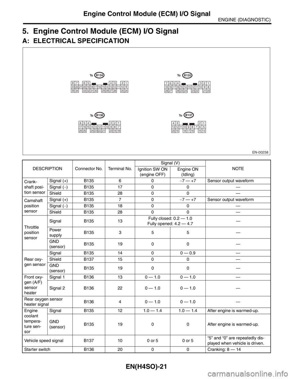
A: ELECTRICAL SPECIFICATION
DESCRIPTION Connector No. Terminal No.Signal (V)
NOTE
Ignition SW ON
(engine OFF)Engine ON
(Idling)
Crank-
shaft posi-
tion sensorSignal (+) B135 6 0−7 — +7 Sensor output waveform
Signal (−) B135 17 0 0 —
Shield B135 28 0 0 —
Camshaft
position
sensorSignal (+) B135 7 0−7 — +7 Sensor output waveform
Signal (−) B135 18 0 0 —
Shield B135 28 0 0 —
Throttle
position
sensorSignal B135 13Fully closed: 0.2 — 1.0
Fully opened: 4.2 — 4.7—
Pow er
supplyB135 3 5 5 —
GND
(sensor)B135 19 0 0 —
Rear oxy-
gen sensorSignal B135 14 0 0 — 0.9 —
Shield B137 15 0 0 —
GND
(sensor)B135 19 0 0 —
Fr o nt ox y-
gen (A/F)
sensor
heaterSignal 1 B136 13 0 — 1.0 0 — 1.0 —
Signal 2 B136 22 0 — 1.0 0 — 1.0 —
Rear oxygen sensor
heater signalB136 4 0 — 1.0 0 — 1.0 —
Engine
coolant
tempera-
ture sen-
sorSignal B135 12 1.0 — 1.4 1.0 — 1.4 After engine is warmed-up.
GND
(sensor)B135 19 0 0 After engine is warmed-up.
Vehicle speed signal B137 10 0 or 5 0 or 5“5” and “0” are repeatedly dis-
played when vehicle is driven.
Starter switch B136 20 0 0 Cranking: 8 — 14
EN-00258
B135B134
B137B136
1234567891011121314151617181920
1 2 3 4
5
6
7 8
910 11 12 13 14 15
16
17 18
19 20 21
22 23
24
25 26 27
28
29
30 31 32
33
34 351 2 3
4
5
6
7
8 910 11
12
13 14
15 16 17
18 19
20
21 22
23 24 25
26 27
28
1 2
3
4 5 6
7
8
910
11 12
13 14 15 16
17
18 19 20 21 22 23
24
25 26
To
To
To To