Page 1928 of 2870
EN(H4DOTC)-295
ENGINE (DIAGNOSTIC)
General Diagnostic Table
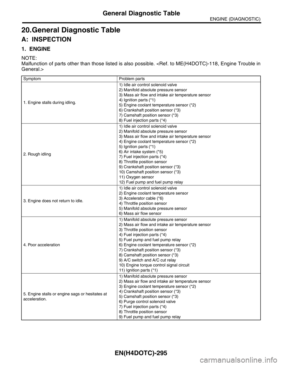
20.General Diagnostic Table
A: INSPECTION
1. ENGINE
NOTE:
Malfunction of parts other than those listed is also possible.
General.>
Symptom Problem parts
1. Engine stalls during idling.1) Idle air control solenoid valve
2) Manifold absolute pressure sensor
3) Mass air flow and intake air temperature sensor
4) Ignition parts (*1)
5) Engine coolant temperature sensor (*2)
6) Crankshaft position sensor (*3)
7) Camshaft position sensor (*3)
8) Fuel injection parts (*4)
2. Rough idling1) Idle air control solenoid valve
2) Manifold absolute pressure sensor
3) Mass air flow and intake air temperature sensor
4) Engine coolant temperature sensor (*2)
5) Ignition parts (*1)
6) Air intake system (*5)
7) Fuel injection parts (*4)
8) Throttle position sensor
9) Crankshaft position sensor (*3)
10) Camshaft position sensor (*3)
11) Oxygen sensor
12) Fuel pump and fuel pump relay
3. Engine does not return to idle.1) Idle air control solenoid valve
2) Engine coolant temperature sensor
3) Accelerator cable (*6)
4) Throttle position sensor
5) Manifold absolute pressure sensor
6) Mass air flow sensor
4. Poor acceleration1) Manifold absolute pressure sensor
2) Mass air flow and intake air temperature sensor
3) Throttle position sensor
4) Fuel injection parts (*4)
5) Fuel pump and fuel pump relay
6) Engine coolant temperature sensor (*2)
7) Crankshaft position sensor (*3)
8) Camshaft position sensor (*3)
9) A/C switch and A/C cut relay
10) Engine torque control signal circuit
11) Ignition parts (*1)
5. Engine stalls or engine sags or hesitates at
acceleration.1) Manifold absolute pressure sensor
2) Mass air flow and intake air temperature sensor
3) Engine coolant temperature sensor (*2)
4) Crankshaft position sensor (*3)
5) Camshaft position sensor (*3)
6) Purge control solenoid valve
7) Fuel injection parts (*4)
8) Throttle position sensor
9) Fuel pump and fuel pump relay
Page 1929 of 2870
EN(H4DOTC)-296
ENGINE (DIAGNOSTIC)
General Diagnostic Table
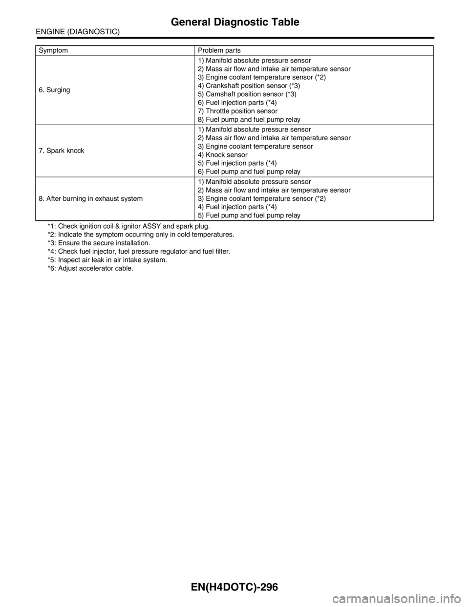
*1: Check ignition coil & ignitor ASSY and spark plug.
*2: Indicate the symptom occurring only in cold temperatures.
*3: Ensure the secure installation.
*4: Check fuel injector, fuel pressure regulator and fuel filter.
*5: Inspect air leak in air intake system.
*6: Adjust accelerator cable. 6. Surging1) Manifold absolute pressure sensor
2) Mass air flow and intake air temperature sensor
3) Engine coolant temperature sensor (*2)
4) Crankshaft position sensor (*3)
5) Camshaft position sensor (*3)
6) Fuel injection parts (*4)
7) Throttle position sensor
8) Fuel pump and fuel pump relay
7. Spark knock1) Manifold absolute pressure sensor
2) Mass air flow and intake air temperature sensor
3) Engine coolant temperature sensor
4) Knock sensor
5) Fuel injection parts (*4)
6) Fuel pump and fuel pump relay
8. After burning in exhaust system1) Manifold absolute pressure sensor
2) Mass air flow and intake air temperature sensor
3) Engine coolant temperature sensor (*2)
4) Fuel injection parts (*4)
5) Fuel pump and fuel pump relay Symptom Problem parts
Page 1931 of 2870
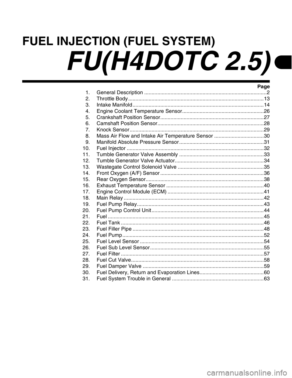
FUEL INJECTION (FUEL SYSTEM)
FU(H4DOTC 2.5)
Page
1. General Description ....................................................................................2
2. Throttle Body .............................................................................................13
3. Intake Manifold ..........................................................................................14
4. Engine Coolant Temperature Sensor........................................................26
5. Crankshaft Position Sensor.......................................................................27
6. Camshaft Position Sensor.........................................................................28
7. Knock Sensor ............................................................................................29
8. Mass Air Flow and Intake Air Temperature Sensor ..................................30
9. Manifold Absolute Pressure Sensor ..........................................................31
10. Fuel Injector ..............................................................................................32
11. Tumble Generator Valve Assembly ..........................................................33
12. Tumble Generator Valve Actuator.............................................................34
13. Wastegate Control Solenoid Valve ...........................................................35
14. Front Oxygen (A/F) Sensor .......................................................................36
15. Rear Oxygen Sensor.................................................................................38
16. Exhaust Temperature Sensor ...................................................................40
17. Engine Control Module (ECM) ..................................................................41
18. Main Relay ................................................................................................42
19. Fuel Pump Relay.......................................................................................43
20. Fuel Pump Control Unit .............................................................................44
21. Fuel ...........................................................................................................45
22. Fuel Tank ..................................................................................................46
23. Fuel Filler Pipe ..........................................................................................48
24. Fuel Pump .................................................................................................52
25. Fuel Level Sensor .....................................................................................54
26. Fuel Sub Level Sensor ..............................................................................55
27. Fuel Filter ..................................................................................................57
28. Fuel Cut Valve...........................................................................................58
29. Fuel Damper Valve ...................................................................................59
30. Fuel Delivery, Return and Evaporation Lines............................................60
31. Fuel System Trouble in General ...............................................................63
Page 1936 of 2870
FU(H4DOTC 2.5)-6
FUEL INJECTION (FUEL SYSTEM)
General Description
3. CRANKSHAFT POSITION, CAMSHAFT POSITION AND KNOCK SENSORS
(1) Crankshaft position sensor (3) Camshaft position sensor LHTightening torque: N·m (kgf-m, ft-lb)
(2) Knock sensor (4) Camshaft position sensor RHT1: 6.4 (0.65, 4.7)
T2: 24 (2.4, 17.4)
FU-01036
T1
(4)
T1
T2
T1
(3)
(2) (1)
Page 1946 of 2870
FU(H4DOTC 2.5)-16
FUEL INJECTION (FUEL SYSTEM)
Intake Manifold
18) Disconnect the knock sensor connector.
19) Disconnect the connector from the camshaft
position sensor.
20) Disconnect the connector from the ignition coil.
RH SIDE
LH SIDE
21) Disconnect the engine harness fixed by clip (A)
from the bracket. RH SIDE
LH SIDE
22) Disconnect the fuel delivery hose, return hose
and evaporation hose.
CAUTION:
Do not spill fuel.
Catch fuel from hoses in a container or cloth.
23) Remove the bolts which secure the intake man-
ifold to the cylinder heads.
24) Remove the intake manifold.
FU-00028
FU-01038
FU-01307
FU-01308
FU-01309 (A)
FU-01310
(A)
FU-00032
FU-01039
Page 1947 of 2870
FU(H4DOTC 2.5)-17
FUEL INJECTION (FUEL SYSTEM)
Intake Manifold
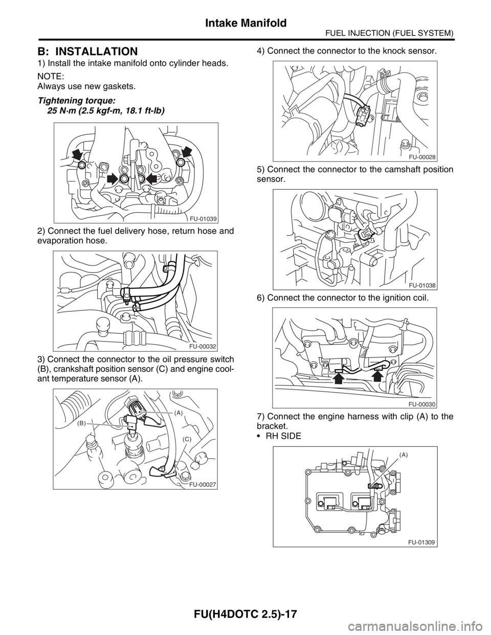
B: INSTALLATION
1) Install the intake manifold onto cylinder heads.
NOTE:
Always use new gaskets.
Tightening torque:
25 N·m (2.5 kgf-m, 18.1 ft-lb)
2) Connect the fuel delivery hose, return hose and
evaporation hose.
3) Connect the connector to the oil pressure switch
(B), crankshaft position sensor (C) and engine cool-
ant temperature sensor (A).4) Connect the connector to the knock sensor.
5) Connect the connector to the camshaft position
sensor.
6) Connect the connector to the ignition coil.
7) Connect the engine harness with clip (A) to the
bracket.
RH SIDE
FU-01039
FU-00032
(A)
(B)
(C)
FU-00027
FU-00028
FU-01038
FU-00030
FU-01309 (A)
Page 1958 of 2870
FU(H4DOTC 2.5)-28
FUEL INJECTION (FUEL SYSTEM)
Camshaft Position Sensor
6. Camshaft Position Sensor
A: REMOVAL
1) Disconnect the ground cable from battery.
2) Disconnect the connector from the camshaft po-
sition sensor RH.
3) Remove the camshaft position sensor RH from
the backside of cylinder head.
4) Remove the camshaft position sensor LH same
as RH side.
B: INSTALLATION
Install in the reverse order of removal.
Tightening torque:
6.4 N·m (0.65 kgf-m, 4.7 ft-lb)
FU-00009
FU-01054
FU-01054
Page 2033 of 2870
EN(H4DOTC 2.5)-9
ENGINE (DIAGNOSTIC)
Electrical Component Location
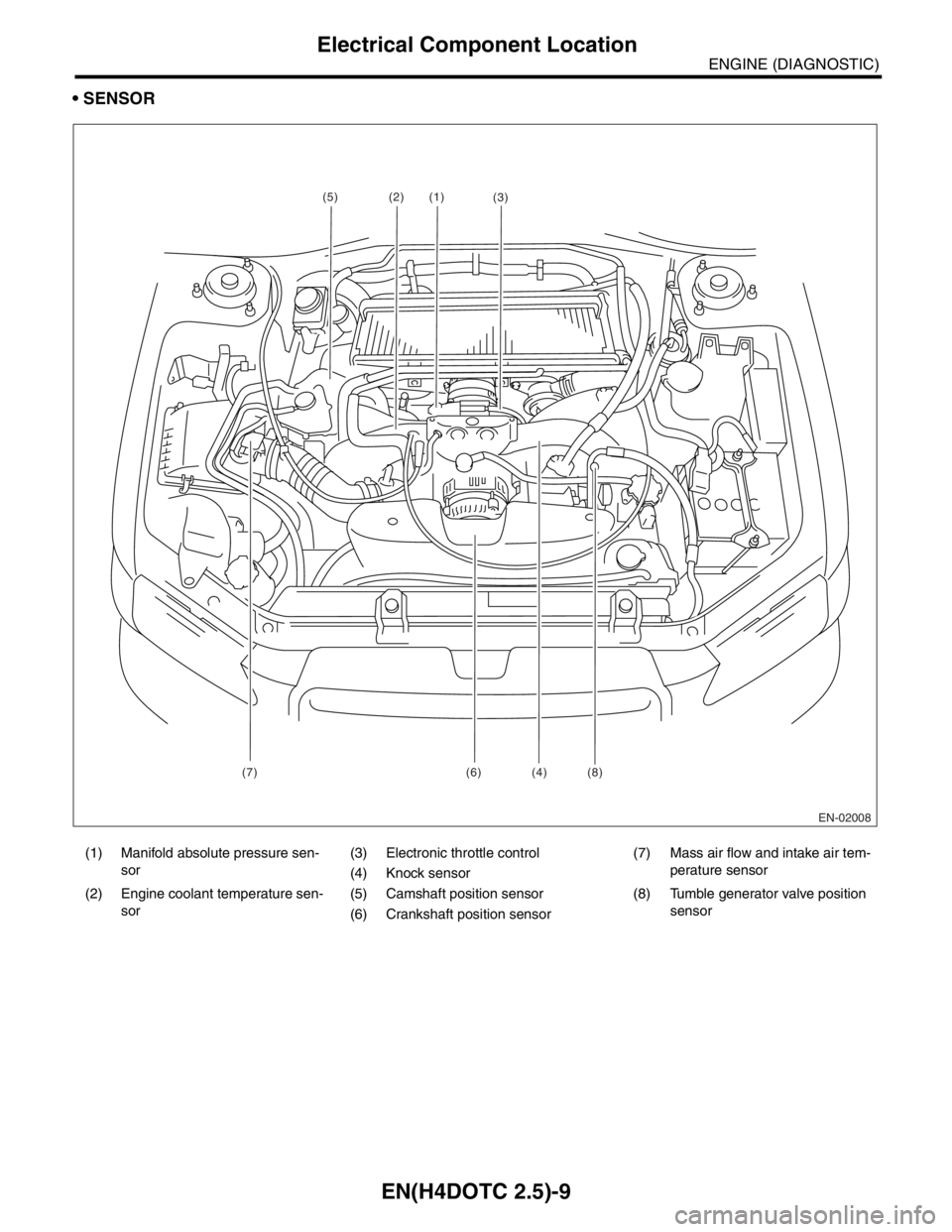
SENSOR
(1) Manifold absolute pressure sen-
sor(3) Electronic throttle control (7) Mass air flow and intake air tem-
perature sensor
(4) Knock sensor
(2) Engine coolant temperature sen-
sor(5) Camshaft position sensor (8) Tumble generator valve position
sensor
(6) Crankshaft position sensor
EN-02008
(1)
(7) (6) (4) (8)(2)
(3)(5)