Page 130 of 173

02-02-2004
Luggage net The stowing rings allow the net to be
placed in different positions.
YOUR 607 IN DETAIL125
Rear sunblind The blind, fitted to the rear parcel shelf, is intended to protect occu-pants from the glare of the sun andthe lights of cars behind
.
Sunblind operation: With the engine running: � Briefly press button Don the cen-
tre console to open it out.
� Briefly press button Dagain to
store it away.
Warning: Do not place anything on
the blind, to avoid it being damaged. Rear armrest This provides access to the ski flap from the passenger compartment. It has two cup holders.
Storage compartmentsThere are two storage compartments located behind the side trim of theboot. The left side storage compartment is fitted with a CD storage bracket foreight single CDs and one double CD.
To access a storage compartment:�
Push the handle downwards and fold down the panel.
Rear shelf compartment This is provided for the storage of a first aid kit. The catch on the lid is designed to withstand a weight of 9 lbs (4kg) onimpact.
Page 150 of 173
![PEUGEOT 607 2004 Owners Manual 02-02-2004
143
TYRE UNDER-INFLATION DETECTION Sensors check the tyre pressure during driving, and trigger a warningin the event of malfunction (speedgreater than 15mph [25 km/h]). Flat tyre When this](/manual-img/29/58354/w960_58354-149.png "PEUGEOT 607 2004 Owners Manual 02-02-2004
143
TYRE UNDER-INFLATION DETECTION Sensors check the tyre pressure during driving, and trigger a warningin the event of malfunction (speedgreater than 15mph [25 km/h]). Flat tyre When this")
02-02-2004
143
TYRE UNDER-INFLATION DETECTION Sensors check the tyre pressure during driving, and trigger a warningin the event of malfunction (speedgreater than 15mph [25 km/h]). Flat tyre When this warning light comes on, accompanied byan audible signal and themessage 'Tyre pressure
low' on the multi-function
display, have the tyre pressurechecked as soon as possible. Puncture
This warning light, accom- panied by an audible signaland the message 'Punc-
tured tyre(s) detected' on
the multi-function display, is
followed by illumination of the
'STOP' warning light.
Stop immediately, avoiding any sud-den movement of the steering wheeland the brakes.
Change the damaged (punctured orvery deflated) tyre, and have the tyrepresure checked as soon as possible.
Note: if the damaged tyre is temporari-
ly stored in the boot, it will again emitthis message to remind you of the
necessity of having it repaired. This willprevent another warning of the sametype being displayed.
Sensor(s) not detected
This warning light, accom-panied by an audible signaland the message ' X tyre
pressure sensor(s) miss-ing ' on the multi-function
display, indicates that under-inflationdetection is absent from one (or sev-eral) tyre(s).
Contact a PEUGEOT dealer to replace the faulty sensor(s). Note: this message is also displayed
when one of the tyres is away from the vehicle (being repaired) or whena wheel without a sensor is fitted.
PRACTICAL INFORMATION
All repairs and changing of tyres on a wheel fittedwith this system must becarried out by a
PEUGEOT dealer.
The tyre under-inflation detec-tion system is an aid to drivingwhich does not replace theneed for the driver to be vigilant
or to drive responsibly. This system does not remove the necessity for having the tyre pres-sure (including that of the spare
wheel) checked regularly, toensure optimum dynamic perfor-mance of the vehicle and to pre-vent premature wear of the tyres,particularly in the case of arduousdriving conditions (heavy load,high speed). The system may temporarily be disturbed by radio broadcasts ona frequency close to it.
Page 151 of 173
02-02-2004
PRACTICAL INFORMATION
144
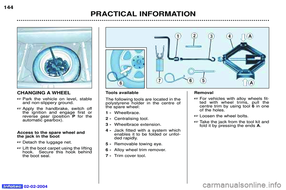
CHANGING A WHEEL
� Park the vehicle on level, stable and non-slippery ground.
� Apply the handbrake, switch offthe ignition and engage first orreverse gear (position Pfor the
automatic gearbox).
Access to the spare wheel andthe jack in the boot � Detach the luggage net.
� Lift the boot carpet using the liftinghook. Secure this hook behindthe boot seal. Tools available The following tools are located in the polystyrene holder in the centre ofthe spare wheel: 1 -
Wheelbrace.
2 - Centralising tool.
3 - Wheelbrace extension.
4 - Jack fitted with a system which enables it to be folded or unfol-
ded rapidly.
5 - Removable towing eye.
6 - Alloy wheel trim remover.
7 - Trim cover tool. Removal
� For vehicles with alloy wheels fit-ted with wheel trims, pull thecentre trim by using tool 6in one
of the holes.
� Loosen the wheel bolts.
� Take the jack from the tool kit andfold it by pressing the ends A.
Page 152 of 173
.
� Extend t")
02-02-2004
PRACTICAL INFORMATION145
�
Fold the jack by pressing at the ends Aand place it in one of the
four locations Eunderneath the
vehicle (the nearest one to thewheel to be changed).
� Extend the jack, first by hand, pul-ling the ends Athen using wheel-
brace 1and the extension 3.
� Remove a wheel bolt at the topand fit the centralising tool 2 in its
place.
� Unscrew the other bolts andremove the wheel.
Fitting a wheel � Position the wheel using the cen-tralising tool to assist you.
� Tighten the bolts by hand andremove the centralising tool. �
Partly tighten the bolts using thewheelbrace.
� Fold the jack and remove it.
� Fully tighten the bolts using thewheelbrace.
� Replace the wheel trim.
� Put the tool holder back in posi-
tion. This helps to keep the bootfloor in its correct position, to pre-vent any deformation of the floorwhen loaded.
� Tighten the spare wheel securingstrap to prevent noise and for yoursafety in the event of impact.
For your safety, alwayschange the wheel:
- on level, stable, non-slippery
ground,
- with the handbrake applied,
- with first or reverse gear enga- ged (position Pfor the automatic
gearbox),
- never go underneath a vehicle which is supported only by a jack (use a ramp).
After changing the wheel:
- have the tightening of the bolts and the tyre pressure checked by a PEUGEOT dealer as soonas possible.
- have the punctured wheel repai- red and refit it to the vehicle assoon as possible.
Tyres fitted with the Tyre Under-Inflation Detection System. These wheels have a pressure
sensor. Have them repaired by a
PEUGEOT dealer.
Page 155 of 173
.
2 - Brake lights/side lights: P21/5 W.
� Detach the luggage net.
� Lift the boot carpet with the lifting hook. Sec")
02-02-2004
Rear lights Rear wing lights
1 - Direction indicators: PY 21 W (amber).
2 - Brake lights/side lights: P21/5 W.
� Detach the luggage net.
� Lift the boot carpet with the lifting hook. Secure this hook behindthe boot seal.
� Unclip the lower part of the silltrim, then dislodge it by pullingupwards.
� Remove the plastic retainer clipsecuring the side trim to the
floor. �
Unclip the side trim.
� Remove the two butterfly nutssecuring the light.
� Remove the eyelet.
� Take out the lamp.
� Turn the lamp holder a quarterturn.
� Change the faulty bulb.
� Lock the bulb holder in place.When refitting it, ensure that thelamp is correctly positioned andsecured.
PRACTICAL INFORMATION
148Direction indicator repeaters:
WY 5 W (amber).
� Push the repeater forwards orbackwards and release the
assembly.
� Hold the connector and turn thetransparent cover a quarter turn.
� Change the bulb.
Amber coloured bulbs
(direction indicators and side repeaters) must bereplaced with bulbs of
identical specification and
colour.
Page 156 of 173
.
2 - Brake lights/side lights: P21/5 W.
� Detach the luggage net.
� Lift the boot carpet with the lifting hook. Sec")
02-02-2004
Rear lights Rear wing lights
1 - Direction indicators: PY 21 W (amber).
2 - Brake lights/side lights: P21/5 W.
� Detach the luggage net.
� Lift the boot carpet with the lifting hook. Secure this hook behindthe boot seal.
� Unclip the lower part of the silltrim, then dislodge it by pullingupwards.
� Remove the plastic retainer clipsecuring the side trim to the
floor. �
Unclip the side trim.
� Remove the two butterfly nutssecuring the light.
� Remove the eyelet.
� Take out the lamp.
� Turn the lamp holder a quarterturn.
� Change the faulty bulb.
� Lock the bulb holder in place.When refitting it, ensure that thelamp is correctly positioned andsecured.
PRACTICAL INFORMATION
148Direction indicator repeaters:
WY 5 W (amber).
� Push the repeater forwards orbackwards and release the
assembly.
� Hold the connector and turn thetransparent cover a quarter turn.
� Change the bulb.
Amber coloured bulbs
(direction indicators and side repeaters) must bereplaced with bulbs of
identical specification and
colour.
Page 157 of 173
02-02-2004
149
PRACTICAL INFORMATION
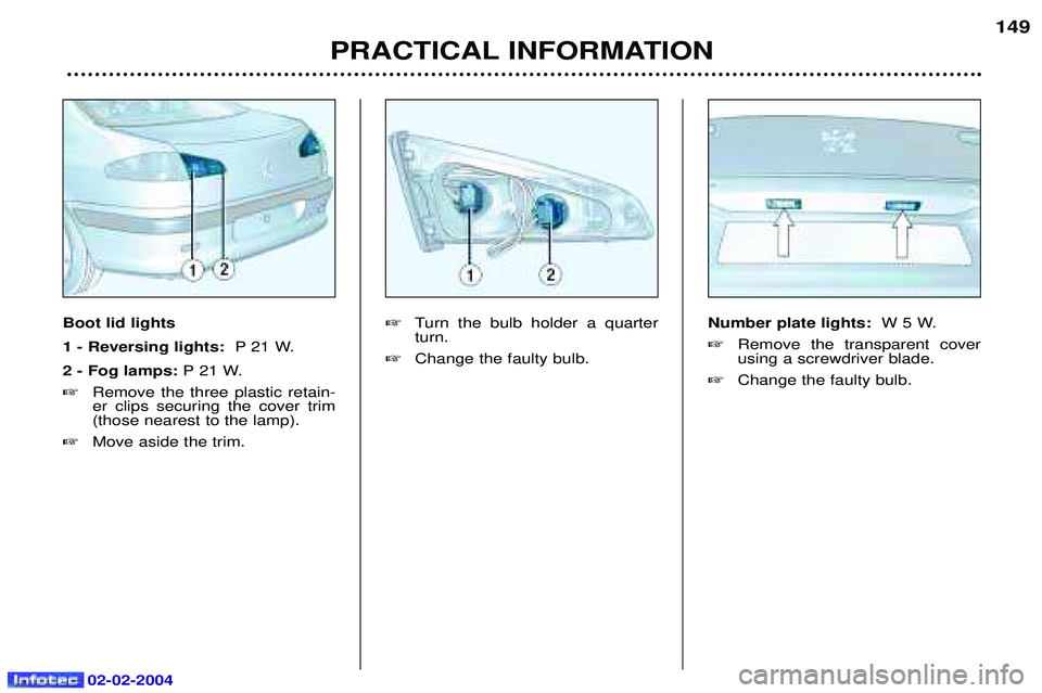
Boot lid lights 1 - Reversing lights: P 21 W.
2 - Fog lamps: P 21 W.
� Remove the three plastic retain- er clips securing the cover trim(those nearest to the lamp).
� Move aside the trim. �
Turn the bulb holder a quarterturn.
� Change the faulty bulb. Number plate lights:
W 5 W.
� Remove the transparent coverusing a screwdriver blade.
� Change the faulty bulb.
Page 164 of 173

02-02-2004
- Do not disconnect theterminals while the engine is running.
- Do not recharge the batteries without disconnecting the termi-nals first.
- Close the windows and sunroof completely before disconnecting
the battery.
- Following reconnection of the battery, switch on the ignitionand wait 1 minute before star-ting the engine to permit initiali-sation of the electronic systems.
However, if minor problems per-sist after this operation, contact
a PEUGEOT dealer.
BATTERY
Vehicles fitted with two batteries Certain vehicles, depending on the country where the vehicle is sold, arefitted with two batteries:
- a battery for starting, located in theengine compartment,
- a service battery, located in the boot.
The starter battery has a label sho- wing that the service battery is in theboot. These are special batteries. If one of them needs to be replaced,
contact a PEUGEOT dealer.
To charge the starter battery with a battery charger: � remove the style cover to gain
access to the starter battery,
� disconnect the battery, Follow the instructions for use given by the battery charger
manufacturer,
� reconnect the battery, starting withthe negative (-) terminal,
� check that the terminals and theconnectors are clean. If they arecovered with sulphate (whitish orgreenish deposit), disconnect andclean them,
� refit the style cover. To start the vehicle from anotherbattery:
�
remove the style cover to gain
access to the starter battery,
�remove the maxi fuse located near
to the starter battery,
�connect the red cable to the positi-ve (+) terminals of the two batteries,
�connect one end of the green orblack cable to the negative (-) ter-
minal of the additional battery,
�connect the other end of the greenor black cable to an earth point onthe vehicle which has broken down,
as far as possible from the battery,
�start the engine and let it run,
�wait for the engine to return to idlethen disconnect the cables,
�drive a few kilometres in order to
recharge the starter battery, thenreplace the maxi fuse near to it,
�refit the style cover.
To recharge the service battery,
contact a PEUGEOT dealer.
PRACTICAL INFORMATION 155
If electrical operations are carried out,
disconnect the starter battery and
remove the maxi fuse located next to it.
It is advisable to disconnect
the starter battery and remove the maxi fuse located next to it, if the
vehicle is not to be used for a period of more than one month.