2004 NISSAN TERRANO electrical system
[x] Cancel search: electrical systemPage 1486 of 1833
System Description
The alternator provides DC voltage to operate the vehicle's electrical system and to keep the battery charged.
The voltage output is controlled by the IC regulator.
Power is supplied at all times to alternator terminal 4 (S) (ZD30DDTi engine models) through:
I10A fuse (No. 31, located in the fuse and fusible link box).
Terminal B supplies power to charge the battery and operate the vehicle's electrical system. Output voltage
is controlled by the IC regulator at terminal 4 (S) detecting the input voltage (ZD30DDTi engine models). The
charging circuit is protected by the 100A fusible link.
The alternator is grounded to the engine block.
With the ignition switch in the ON or START position, power is supplied
I through 10A fuse [No. 12, located in the fuse block (J/B)]
I to combination meter terminal 28 for the charge warning lamp.
Ground is supplied to terminal 2 of the combination meter through terminal 1(L) (TD27Ti engine models) or
3(L) (ZD30DDTi engine models) of the alternator. With power and ground supplied, the charge warning lamp
will illuminate. When the alternator is providing sufficient voltage with the engine running, the ground is opened
and the charge warning lamp will go off.
If the charge warning lamp illuminates with the engine running, a malfunction is indicated.
CHARGING SYSTEM
SC-23
http://vnx.su/
Page 1494 of 1833
ELECTRICAL SYSTEMSECTION
EL
When you read wiring diagrams:
I Read GI section, ªHOW TO READ WIRING DIAGRAMSº.
CONTENTS
PRECAUTIONS ...............................................................4
Supplemental Restraint System (SRS) ²AIR
BAG² and²SEAT BELT PRE-TENSIONER² ...............4
Wiring Diagrams and Trouble Diagnoses....................4
HARNESS CONNECTOR ................................................5
Description ...................................................................5
STANDARDIZED RELAYS ..............................................6
Description ...................................................................6
POWER SUPPLY ROUTING ...........................................8
Schematic ....................................................................8
Wiring Diagram - POWER - ......................................10
Fuse ........................................................................\
...19
Fusible Link................................................................19
Circuit Breaker Inspection .........................................19
GROUND DISTRIBUTION .............................................20
COMBINATION SWITCH ...............................................25
Check ........................................................................\
.25
Replacement ..............................................................26
STEERING SWITCH ......................................................27
Check ........................................................................\
.27
HEADLAMP - Without Daytime Light System - .........28
Wiring Diagram - H/LAMP -.......................................28
Trouble Diagnoses.....................................................31
HEADLAMP - Daytime Light System - .......................32
Operation ...................................................................32
System Description ....................................................32
Schematic ..................................................................33
Wiring Diagram - DTRL - ...........................................34
Trouble Diagnoses.....................................................40
HEADLAMP - Headlamp Aiming Control - .................41
Description .................................................................41
Replacing Headlamp Aiming Actuator .......................42
Wiring Diagram - H/AIM - ..........................................43
Trouble Diagnoses.....................................................46 HEADLAMP
...................................................................47
Bulb Replacement .....................................................47
Aiming Adjustment .....................................................47
EXTERIOR LAMP ..........................................................49
Wiring Diagram - TAIL/L - ..........................................49
Wiring Diagram - STOP/L - .......................................52
Wiring Diagram - BACK/L - .......................................53
Wiring Diagram - F/FOG - .........................................55
Front Fog Lamp Aiming Adjustment ..........................57
Wiring Diagram - R/FOG -.........................................58
System Description ....................................................59
Schematic ..................................................................61
Wiring Diagram - TURN - ..........................................62
Trouble Diagnoses.....................................................66
INTERIOR LAMP ...........................................................67
Schematic ..................................................................67
Wiring Diagram - ILL - ...............................................68
System Description ....................................................72
Wiring Diagram - INT/L - ...........................................74
Trouble Diagnoses.....................................................78
METER AND GAUGES .................................................82
System Description ....................................................82
Combination Meter ....................................................84
Schematic ..................................................................85
Wiring Diagram - METER - .......................................86
Combination Meter Self-Diagnosis ............................90
Trouble Diagnoses.....................................................92
Components Inspection .............................................97
Fuel Level Sensor Unit Check...................................98
Thermal Transmitter Check .......................................98
WARNING LAMPS AND CHIME ...................................99
Schematic ..................................................................99
Wiring Diagram - WARN - .......................................100
Electrical Components Inspection ........................... 110
http://vnx.su/
Page 1495 of 1833
Oil Pressure Switch Check ...................................... 110
Wiring Diagram - CHIME - ...................................... 111
WIPER AND WASHER ................................................ 112
Wiring Diagram - WIPER - ...................................... 112
Wiring Diagram - WIP/R -........................................ 114
Installation ................................................................ 116
Washer Nozzle Adjustment ..................................... 117
Check Valve ............................................................. 117
Wiring Diagram - HLC - ........................................... 118
HORN, CIGARETTE LIGHTER AND CLOCK ............122
Wiring Diagram - HORN - .......................................122
Wiring Diagram - CIGAR -.......................................123
Wiring Diagram - CLOCK -......................................124
REAR WINDOW DEFOGGER AND DOOR
MIRROR DEFOGGER .................................................125
System Description ..................................................125
Wiring Diagram - DEF - ...........................................126
Trouble Diagnoses...................................................128
Filament Check ........................................................132
Filament Repair .......................................................133
AUDIO ........................................................................\
..134
System Description ..................................................134
Schematic ................................................................136
Wiring Diagram - AUDIO - .......................................138
Wiring Diagram - REMOTE -...................................145
Trouble Diagnoses...................................................147
Inspection.................................................................149
Location of Roof Mounted Antenna .........................150
HEATED SEAT ............................................................151
Wiring Diagram - HSEAT - ......................................151
SUNROOF ....................................................................153
Wiring Diagram - SROOF - .....................................153
DOOR MIRROR ...........................................................154
Wiring Diagram - MIRROR - ...................................154
POWER WINDOW .......................................................156
System Description ..................................................156
Schematic ................................................................158
Wiring Diagram - WINDOW - ..................................159
Trouble Diagnoses...................................................162
POWER DOOR LOCK .................................................163
System Description ..................................................163
Schematic ................................................................164
Wiring Diagram - D/LOCK -.....................................166
Trouble Diagnoses...................................................171
POWER DOOR LOCK - SUPER LOCK - ...................179
Component Parts Location ......................................179
System Description ..................................................180
Schematic ................................................................182 Wiring Diagram - S/LOCK - .....................................184
Trouble Diagnoses...................................................192
MULTI-REMOTE CONTROL SYSTEM .......................202
System Description ..................................................202
Schematic ................................................................204
Wiring Diagram - MULTI - .......................................205
Trouble Diagnoses...................................................213
ID Code Entry Procedure ........................................215
TIME CONTROL UNIT (TCU) .....................................216
System Description ..................................................216
Trouble Diagnosis ....................................................218
Schematic ................................................................220
NATS (Nissan Anti-Theft System) .............................222
System Description ..................................................222
System Composition ................................................223
Component Parts Location ......................................224
Wiring Diagram - NATS -.........................................225
CONSULT-II .............................................................229
Trouble Diagnoses...................................................231
How to Replace NATS IMMU ..................................242
THEFT WARNING SYSTEM .......................................243
Components Parts and Harness Connector
Location ...................................................................243
System Description ..................................................244
Theft Warning System/Schematic ...........................247
Wiring Diagram - THEFT -.......................................248
Trouble Diagnoses...................................................264
LOCATION OF ELECTRICAL UNITS .........................275
Engine Compartment ...............................................275
Passenger Compartment/LHD Models ....................276
Passenger Compartment/RHD Models ...................278
HARNESS LAYOUT ....................................................280
How to Read Harness Layout .................................280
Outline......................................................................281
Main Harness...........................................................282
EFC Harness ...........................................................298
Engine Harness .......................................................310
Body Harness ..........................................................312
Chassis Harness......................................................320
Room Lamp Harness...............................................321
Tailgate Harness ......................................................322
Door Harness (LH side)...........................................323
Door Harness (RH side) ..........................................324
BULB SPECIFICATIONS ............................................325
Headlamps ...............................................................325
Exterior Lamps.........................................................325
Interior Lamps ..........................................................325
WIRING DIAGRAM CODES (CELL CODES) .............326
CONTENTS(Cont'd)
EL-2
http://vnx.su/
Page 1497 of 1833
Supplemental Restraint System (SRS) ªAIR
BAGº and ªSEAT BELT PRE-TENSIONERº
The Supplemental Restraint System such as ªAIR BAGº and ªSEAT BELT PRE-TENSIONERº used along with
a seat belt, helps to reduce the risk or severity of injury to the driver and front passenger for certain types of
collision. The SRS system composition which is available to NISSAN MODEL R20 is as follows (The compo-
sition varies according to the destination and optional equipment.):
IFor a frontal collision
The Supplemental Restraint System consists of driver air bag module (located in the center of the steer-
ing wheel), front passenger air bag module (located on the instrument panel on passenger side), front seat
belt pre-tensioners, a diagnosis sensor unit, warning lamp, wiring harness and spiral cable.
I For a side collision
The Supplemental Restraint System consists of front side air bag module (located in the outer side of front
seat), side air bag (satellite) sensor, diagnosis sensor unit (one of components of air bags for a frontal
collision), wiring harness, warning lamp (one of components of air bags for a frontal collision).
Information necessary to service the system safely is included in the RS sectionof this Service Manual.
WARNING:
I To avoid rendering the SRS inoperative, which could increase the risk of personal injury or death
in the event of a collision which would result in air bag inflation, all maintenance should be per-
formed by an authorized NISSAN dealer.
I Improper maintenance, including incorrect removal and installation of the SRS, can lead to per-
sonal injury caused by unintentional activation of the system. For removal of Spiral Cable and Air
Bag Module, see the RS section.
I Do not use electrical test equipment on any circuit related to the SRS unless instructed to in this
Service Manual. SRS wiring harnesses can be identified by yellow harness connector.
Wiring Diagrams and Trouble Diagnoses
When you read wiring diagrams, refer to the following:
IGI section, ªHOW TO READ WIRING DIAGRAMSº
I EL section, ªPOWER SUPPLY ROUTINGº for power distribution circuit
When you perform trouble diagnoses, refer to the following:
I GI section, ªHOW TO FOLLOW TEST GROUPS IN TROUBLE DIAGNOSESº
I GI section, ªHOW TO PERFORM EFFICIENT DIAGNOSIS FOR AN ELECTRICAL INCIDENTº
PRECAUTIONS
EL-4
http://vnx.su/
Page 1828 of 1833
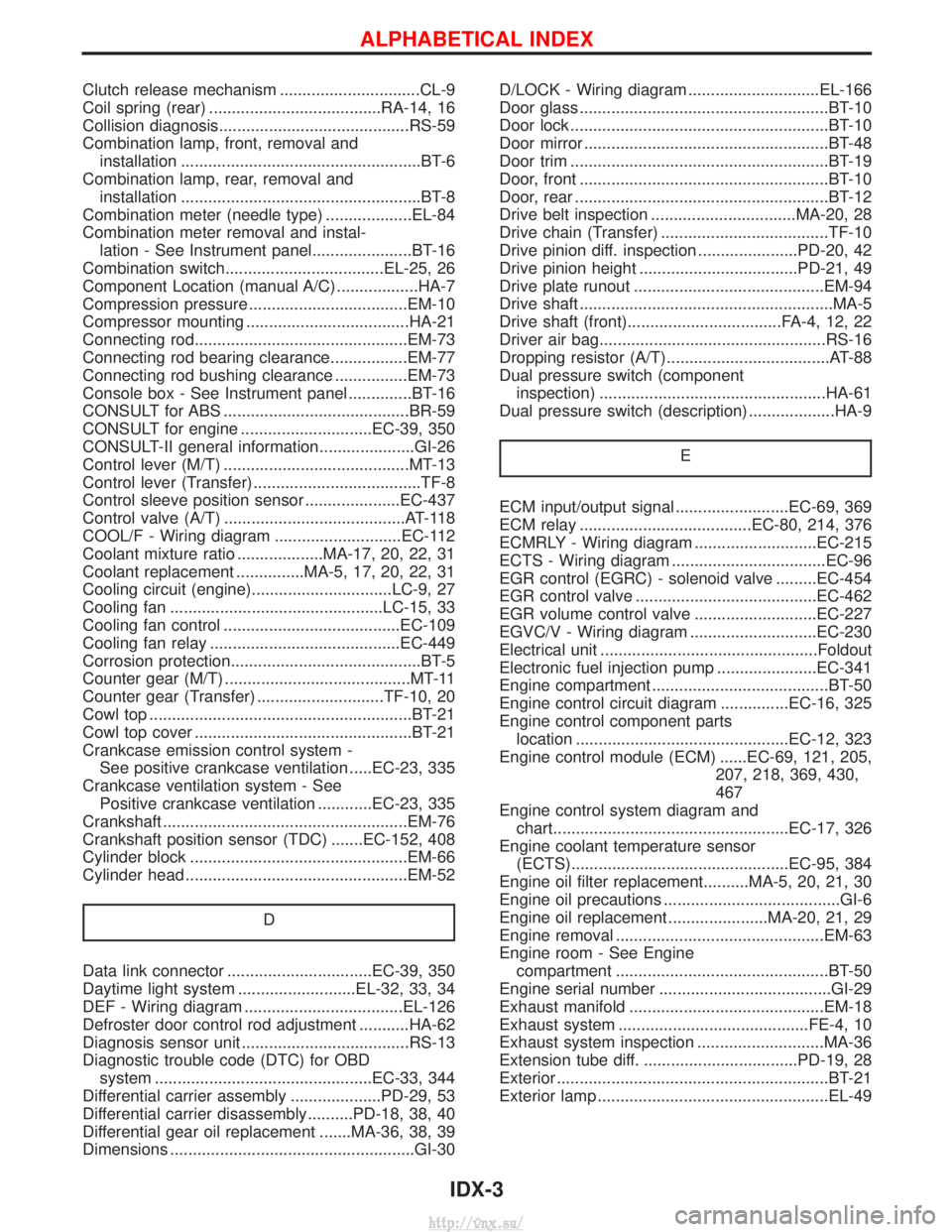
Clutch release mechanism ...............................CL-9
Coil spring (rear) ......................................RA-14, 16
Collision diagnosis..........................................RS-59
Combination lamp, front, removal andinstallation .....................................................BT-6
Combination lamp, rear, removal and installation .....................................................BT-8
Combination meter (needle type) ...................EL-84
Combination meter removal and instal- lation - See Instrument panel......................BT-16
Combination switch...................................EL-25, 26
Component Location (manual A/C) ..................HA-7
Compression pressure ...................................EM-10
Compressor mounting ....................................HA-21
Connecting rod...............................................EM-73
Connecting rod bearing clearance.................EM-77
Connecting rod bushing clearance ................EM-73
Console box - See Instrument panel ..............BT-16
CONSULT for ABS .........................................BR-59
CONSULT for engine .............................EC-39, 350
CONSULT-II general information.....................GI-26
Control lever (M/T) .........................................MT-13
Control lever (Transfer) .....................................TF-8
Control sleeve position sensor .....................EC-437
Control valve (A/T) ........................................AT-118
COOL/F - Wiring diagram ............................EC-112
Coolant mixture ratio ...................MA-17, 20, 22, 31
Coolant replacement ...............MA-5, 17, 20, 22, 31
Cooling circuit (engine)...............................LC-9, 27
Cooling fan ...............................................LC-15, 33
Cooling fan control .......................................EC-109
Cooling fan relay ..........................................EC-449
Corrosion protection..........................................BT-5
Counter gear (M/T) .........................................MT-11
Counter gear (Transfer) ............................TF-10, 20
Cowl top ..........................................................BT-21
Cowl top cover ................................................BT-21
Crankcase emission control system - See positive crankcase ventilation .....EC-23, 335
Crankcase ventilation system - See Positive crankcase ventilation ............EC-23, 335
Crankshaft ......................................................EM-76
Crankshaft position sensor (TDC) .......EC-152, 408
Cylinder block ................................................EM-66
Cylinder head .................................................EM-52
D
Data link connector ................................EC-39, 350
Daytime light system ..........................EL-32, 33, 34
DEF - Wiring diagram ...................................EL-126
Defroster door control rod adjustment ...........HA-62
Diagnosis sensor unit .....................................RS-13
Diagnostic trouble code (DTC) for OBDsystem ................................................EC-33, 344
Differential carrier assembly ....................PD-29, 53
Differential carrier disassembly..........PD-18, 38, 40
Differential gear oil replacement .......MA-36, 38, 39
Dimensions ......................................................GI-30 D/LOCK - Wiring diagram .............................EL-166
Door glass .......................................................BT-10
Door lock .........................................................BT-10
Door mirror ......................................................BT-48
Door trim .........................................................BT-19
Door, front .......................................................BT-10
Door, rear ........................................................BT-12
Drive belt inspection ................................MA-20, 28
Drive chain (Transfer) .....................................TF-10
Drive pinion diff. inspection ......................PD-20, 42
Drive pinion height ...................................PD-21, 49
Drive plate runout ..........................................EM-94
Drive shaft ........................................................MA-5
Drive shaft (front)..................................FA-4, 12, 22
Driver air bag..................................................RS-16
Dropping resistor (A/T)....................................AT-88
Dual pressure switch (component
inspection) ..................................................HA-61
Dual pressure switch (description) ...................HA-9
E
ECM input/output signal .........................EC-69, 369
ECM relay ......................................EC-80, 214, 376
ECMRLY - Wiring diagram ...........................EC-215
ECTS - Wiring diagram ..................................EC-96
EGR control (EGRC) - solenoid valve .........EC-454
EGR control valve ........................................EC-462
EGR volume control valve ...........................EC-227
EGVC/V - Wiring diagram ............................EC-230
Electrical unit ................................................Foldout
Electronic fuel injection pump ......................EC-341
Engine compartment .......................................BT-50
Engine control circuit diagram ...............EC-16, 325
Engine control component partslocation ...............................................EC-12, 323
Engine control module (ECM) ......EC-69, 121, 205, 207, 218, 369, 430,
467
Engine control system diagram and chart....................................................EC-17, 326
Engine coolant temperature sensor (ECTS)................................................EC-95, 384
Engine oil filter replacement..........MA-5, 20, 21, 30
Engine oil precautions .......................................GI-6
Engine oil replacement ......................MA-20, 21, 29
Engine removal ..............................................EM-63
Engine room - See Engine compartment ...............................................BT-50
Engine serial number ......................................GI-29
Exhaust manifold ...........................................EM-18
Exhaust system ..........................................FE-4, 10
Exhaust system inspection ............................MA-36
Extension tube diff. ..................................PD-19, 28
Exterior ............................................................BT-21
Exterior lamp ...................................................EL-49
ALPHABETICAL INDEX
IDX-3
http://vnx.su/
Page 1830 of 1833
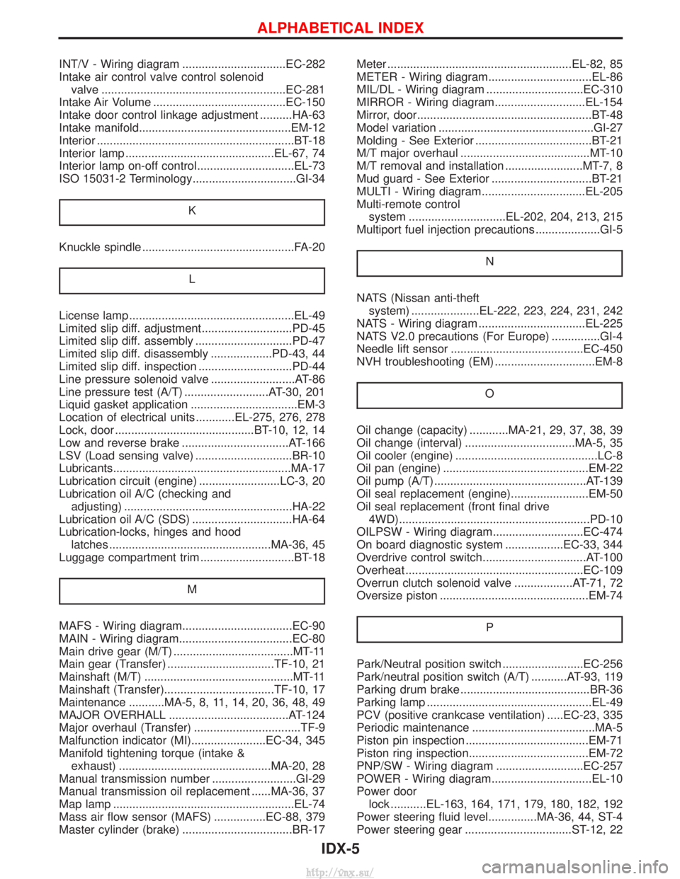
INT/V - Wiring diagram ................................EC-282
Intake air control valve control solenoidvalve .........................................................EC-281
Intake Air Volume .........................................EC-150
Intake door control linkage adjustment ..........HA-63
Intake manifold...............................................EM-12
Interior .............................................................BT-18
Interior lamp ..............................................EL-67, 74
Interior lamp on-off control..............................EL-73
ISO 15031-2 Terminology................................GI-34
K
Knuckle spindle ...............................................FA-20 L
License lamp ...................................................EL-49
Limited slip diff. adjustment............................PD-45
Limited slip diff. assembly ..............................PD-47
Limited slip diff. disassembly ...................PD-43, 44
Limited slip diff. inspection .............................PD-44
Line pressure solenoid valve ..........................AT-86
Line pressure test (A/T) ..........................AT-30, 201
Liquid gasket application .................................EM-3
Location of electrical units ............EL-275, 276, 278
Lock, door ...........................................BT-10, 12, 14
Low and reverse brake .................................AT-166
LSV (Load sensing valve) ..............................BR-10
Lubricants.......................................................MA-17
Lubrication circuit (engine) .........................LC-3, 20
Lubrication oil A/C (checking andadjusting) ....................................................HA-22
Lubrication oil A/C (SDS) ...............................HA-64
Lubrication-locks, hinges and hood latches ..................................................MA-36, 45
Luggage compartment trim .............................BT-18
M
MAFS - Wiring diagram..................................EC-90
MAIN - Wiring diagram...................................EC-80
Main drive gear (M/T) .....................................MT-11
Main gear (Transfer) .................................TF-10, 21
Mainshaft (M/T) ..............................................MT-11
Mainshaft (Transfer)..................................TF-10, 17
Maintenance ...........MA-5, 8, 11, 14, 20, 36, 48, 49
MAJOR OVERHALL .....................................AT-124
Major overhaul (Transfer) .................................TF-9
Malfunction indicator (MI).......................EC-34, 345
Manifold tightening torque (intake &exhaust) ...............................................MA-20, 28
Manual transmission number ..........................GI-29
Manual transmission oil replacement ......MA-36, 37
Map lamp ........................................................EL-74
Mass air flow sensor (MAFS) ................EC-88, 379
Master cylinder (brake) ..................................BR-17 Meter .........................................................EL-82, 85
METER - Wiring diagram................................EL-86
MIL/DL - Wiring diagram ..............................EC-310
MIRROR - Wiring diagram............................EL-154
Mirror, door......................................................BT-48
Model variation ................................................GI-27
Molding - See Exterior ....................................BT-21
M/T major overhaul ........................................MT-10
M/T removal and installation ........................MT-7, 8
Mud guard - See Exterior ...............................BT-21
MULTI - Wiring diagram................................EL-205
Multi-remote control
system ..............................EL-202, 204, 213, 215
Multiport fuel injection precautions ....................GI-5
N
NATS (Nissan anti-theftsystem) .....................EL-222, 223, 224, 231, 242
NATS - Wiring diagram .................................EL-225
NATS V2.0 precautions (For Europe) ...............GI-4
Needle lift sensor .........................................EC-450
NVH troubleshooting (EM) ...............................EM-8
O
Oil change (capacity) ............MA-21, 29, 37, 38, 39
Oil change (interval) ..................................MA-5, 35
Oil cooler (engine) ............................................LC-8
Oil pan (engine) .............................................EM-22
Oil pump (A/T)...............................................AT-139
Oil seal replacement (engine)........................EM-50
Oil seal replacement (front final drive4WD)...........................................................PD-10
OILPSW - Wiring diagram............................EC-474
On board diagnostic system ..................EC-33, 344
Overdrive control switch................................AT-100
Overheat .......................................................EC-109
Overrun clutch solenoid valve ..................AT-71, 72
Oversize piston ..............................................EM-74
P
Park/Neutral position switch .........................EC-256
Park/neutral position switch (A/T) ...........AT-93, 119
Parking drum brake ........................................BR-36
Parking lamp ...................................................EL-49
PCV (positive crankcase ventilation) .....EC-23, 335
Periodic maintenance ......................................MA-5
Piston pin inspection ......................................EM-71
Piston ring inspection.....................................EM-72
PNP/SW - Wiring diagram ...........................EC-257
POWER - Wiring diagram...............................EL-10
Power doorlock ...........EL-163, 164, 171, 179, 180, 182, 192
Power steering fluid level...............MA-36, 44, ST-4
Power steering gear .................................ST-12, 22
ALPHABETICAL INDEX
IDX-5
http://vnx.su/