2004 NISSAN TERRANO electrical system
[x] Cancel search: electrical systemPage 319 of 1833

REAL TIME DIAGNOSIS IN DATA MONITOR MODE
CONSULT-II has two kinds of triggers and they can be selected by
touching ªSETTINGº in ªDATA MONITORº mode.
1) ªAUTO TRIGº (Automatic trigger):
IThe malfunction will be identified on the CONSULT-II screen in
real time.
In other words, DTC will be displayed if the malfunction is
detected by ECM.
At the moment a malfunction is detected by ECM, ªMONITORº
in ªDATA MONITORº screen is changed to ªRecording Data ...
xx%º as shown at left, and the data after the malfunction detec-
tion is recorded. Then when the percentage reached 100%,
ªREAL-TIME DIAGº screen is displayed. If ªSTOPº is touched
on the screen during ªRecording Data ... xx%º, ªREAL-TIME
DIAGº screen is also displayed.
The recording time after the malfunction detection and the
recording speed can be changed by ªTRIGGER POINTº and
ªRecording Speedº. Refer to CONSULT-II OPERATION
MANUAL.
2) ªMANU TRIGº (Manual trigger):
I DTC will not be displayed automatically on CONSULT-II screen
even though a malfunction is detected by ECM.
DATA MONITOR can be performed continuously even though
a malfunction is detected.
Use these triggers as follows:
1) ªAUTO TRIGº
I While trying to detect the DTC by performing the ªDTC Confir-
mation Procedureº, be sure to select to ªDATA MONITOR
(AUTO TRIG)º mode. You can confirm the malfunction at the
moment it is detected.
I While narrowing down the possible causes, CONSULT-II
should be set in ªDATA MONITOR (AUTO TRIG)º mode, espe-
cially in case the incident is intermittent.
When you are inspecting the circuit by gently shaking (or twist-
ing) the suspicious connectors, components and harness in the
ªDTC Confirmation Procedureº, the moment a malfunction is
found the DTC will be displayed. (Refer to GI section, ªIncident
Simulation Testsº in ªHOW TO PERFORM EFFICIENT DIAG-
NOSIS FOR AN ELECTRICAL INCIDENTº.)
2) ªMANU TRIGº
I If the malfunction is displayed as soon as ªDATA MONITORº is
selected, reset CONSULT-II to ªMANU TRIGº. By selecting
ªMANU TRIGº you can monitor and store the data. The data
can be utilized for further diagnosis, such as a comparison with
the value for the normal operating condition.
SEF373Y
SEF707X
ON BOARD DIAGNOSTIC SYSTEM DESCRIPTIONZD30DDTi
CONSULT-II (Cont'd)
EC-44
http://vnx.su/
Page 324 of 1833
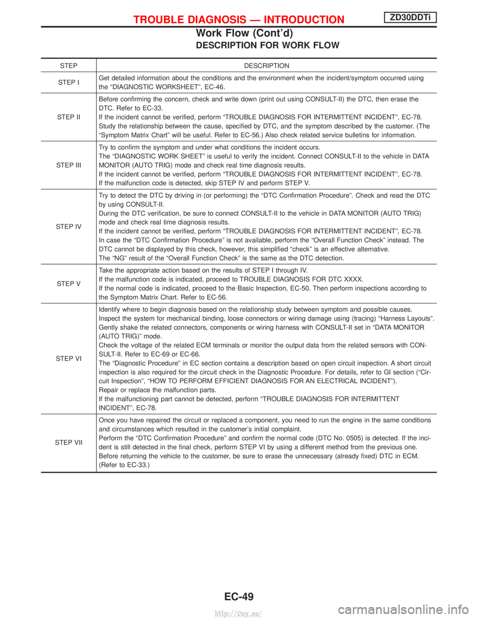
DESCRIPTION FOR WORK FLOW
STEPDESCRIPTION
STEP I Get detailed information about the conditions and the environment when the incident/symptom occurred using
the ªDIAGNOSTIC WORKSHEETº, EC-46.
STEP II Before confirming the concern, check and write down (print out using CONSULT-II) the DTC, then erase the
DTC. Refer to EC-33.
If the incident cannot be verified, perform ªTROUBLE DIAGNOSIS FOR INTERMITTENT INCIDENTº, EC-78.
Study the relationship between the cause, specified by DTC, and the symptom described by the customer. (The
ªSymptom Matrix Chartº will be useful. Refer to EC-56.) Also check related service bulletins for information.
STEP III Try to confirm the symptom and under what conditions the incident occurs.
The ªDIAGNOSTIC WORK SHEETº is useful to verify the incident. Connect CONSULT-II to the vehicle in DATA
MONITOR (AUTO TRIG) mode and check real time diagnosis results.
If the incident cannot be verified, perform ªTROUBLE DIAGNOSIS FOR INTERMITTENT INCIDENTº, EC-78.
If the malfunction code is detected, skip STEP IV and perform STEP V.
STEP IV Try to detect the DTC by driving in (or performing) the ªDTC Confirmation Procedureº. Check and read the DTC
by using CONSULT-II.
During the DTC verification, be sure to connect CONSULT-II to the vehicle in DATA MONITOR (AUTO TRIG)
mode and check real time diagnosis results.
If the incident cannot be verified, perform ªTROUBLE DIAGNOSIS FOR INTERMITTENT INCIDENTº, EC-78.
In case the ªDTC Confirmation Procedureº is not available, perform the ªOverall Function Checkº instead. The
DTC cannot be displayed by this check, however, this simplified ªcheckº is an effective alternative.
The ªNGº result of the ªOverall Function Checkº is the same as the DTC detection.
STEP V Take the appropriate action based on the results of STEP I through IV.
If the malfunction code is indicated, proceed to TROUBLE DIAGNOSIS FOR DTC XXXX.
If the normal code is indicated, proceed to the Basic Inspection, EC-50. Then perform inspections according to
the Symptom Matrix Chart. Refer to EC-56.
STEP VI Identify where to begin diagnosis based on the relationship study between symptom and possible causes.
Inspect the system for mechanical binding, loose connectors or wiring damage using (tracing) ªHarness Layoutsº.
Gently shake the related connectors, components or wiring harness with CONSULT-II set in ªDATA MONITOR
(AUTO TRIG)º mode.
Check the voltage of the related ECM terminals or monitor the output data from the related sensors with CON-
SULT-II. Refer to EC-69 or EC-66.
The ªDiagnostic Procedureº in EC section contains a description based on open circuit inspection. A short circuit
inspection is also required for the circuit check in the Diagnostic Procedure. For details, refer to GI section (ªCir-
cuit Inspectionº, ªHOW TO PERFORM EFFICIENT DIAGNOSIS FOR AN ELECTRICAL INCIDENTº).
Repair or replace the malfunction parts.
If the malfunctioning part cannot be detected, perform ªTROUBLE DIAGNOSIS FOR INTERMITTENT
INCIDENTº, EC-78.
STEP VII Once you have repaired the circuit or replaced a component, you need to run the engine in the same conditions
and circumstances which resulted in the customer's initial complaint.
Perform the ªDTC Confirmation Procedureº and confirm the normal code (DTC No. 0505) is detected. If the inci-
dent is still detected in the final check, perform STEP VI by using a different method from the previous one.
Before returning the vehicle to the customer, be sure to erase the unnecessary (already fixed) DTC in ECM.
(Refer to EC-33.)
TROUBLE DIAGNOSIS Ð INTRODUCTIONZD30DDTi
Work Flow (Cont'd)
EC-49
http://vnx.su/
Page 502 of 1833
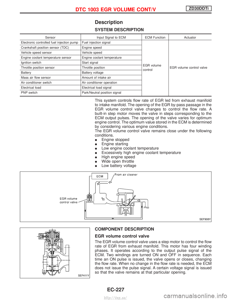
Description
SYSTEM DESCRIPTION
SensorInput Signal to ECMECM FunctionActuator
Electronic controlled fuel injection pump Fuel injection signal
EGR volume
controlEGR volume control valve
Crankshaft position sensor (TDC) Engine speed
Vehicle speed sensor
Vehicle speed
Engine coolant temperature sensor Engine coolant temperature
Ignition switch Start signal
Throttle position sensor Throttle position
Battery Battery voltage
Mass air flow sensor Amount of intake air
Air conditioner switch Air conditioner operation
Electrical load Electrical load signal
PNP switch Park/Neutral position signal
This system controls flow rate of EGR led from exhaust manifold
to intake manifold. The opening of the EGR by-pass passage in the
EGR volume control valve changes to control the flow rate. A
built-in step motor moves the valve in steps corresponding to the
ECM output pulses. The opening of the valve varies for optimum
engine control. The optimum value stored in the ECM is determined
by considering various engine conditions.
The EGR volume control valve remains close under the following
conditions.
IEngine stopped
I Engine starting
I Low engine coolant temperature
I Excessively high engine coolant temperature
I High engine speed
I Wide open throttle
I Low battery voltage
COMPONENT DESCRIPTION
EGR volume control valve
The EGR volume control valve uses a step motor to control the flow
rate of EGR from exhaust manifold. This motor has four winding
phases. It operates according to the output pulse signal of the
ECM. Two windings are turned ON and OFF in sequence. Each
time an ON pulse is issued, the valve opens or closes, changing
the flow rate. When no change in the flow rate is needed, the ECM
does not issue the pulse signal. A certain voltage signal is issued
so that the valve remains at that particular opening.
SEF908Y
SEF411Y
DTC 1003 EGR VOLUME CONT/VZD30DDTi
EC-227
http://vnx.su/
Page 590 of 1833
Precautions
SUPPLEMENTAL RESTRAINT SYSTEM (SRS) ªAIR BAGº AND ªSEAT BELT
PRE-TENSIONERº
The Supplemental Restraint System such as ªAIR BAGº and ªSEAT BELT PRE-TENSIONERº used along with
a seat belt, helps to reduce the risk or severity of injury to the driver and front passenger for certain types of
collision. The SRS composition which is available to NISSAN MODEL R20 is as follows (The composition
varies according to the destination and optional equipment.):
IFor a frontal collision
The Supplemental Restraint System consists of driver air bag module (located in the center of the steer-
ing wheel), front passenger air bag module (located on the instrument panel on passenger side), front seat
belt pre-tensioners, a diagnosis sensor unit, warning lamp, wiring harness and spiral cable.
I For a side collision
The Supplemental Restraint System consists of front side air bag module (located in the outer side of front
seat), side air bag (satellite) sensor, diagnosis sensor unit (one of components of air bags for a frontal
collision), wiring harness, warning lamp (one of components of air bags for a frontal collision).
WARNING:
I To avoid rendering the SRS inoperative, which could increase the risk of personal injury or death
in the event of a collision which would result in air bag inflation, all maintenance should be per-
formed by an authorized NISSAN dealer.
I Improper maintenance, including incorrect removal and installation of the SRS, can lead to per-
sonal injury caused by unintentional activation of the system.
I Do not use electrical test equipment on any circuit related to the SRS unless instructed to in this
Service Manual. Spiral cable and wiring harnesses covered with yellow insulation tape either just
before the harness connectors or for the complete harness are related to the SRS.
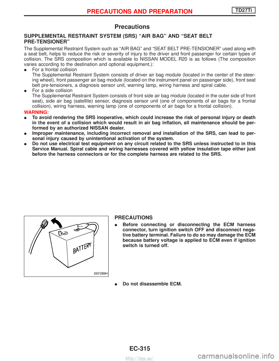
PRECAUTIONS
IBefore connecting or disconnecting the ECM harness
connector, turn ignition switch OFF and disconnect nega-
tive battery terminal. Failure to do so may damage the ECM
because battery voltage is applied to ECM even if ignition
switch is turned off.
I Do not disassemble ECM.
SEF289H
PRECAUTIONS AND PREPARATIONTD27Ti
EC-315
http://vnx.su/
Page 636 of 1833
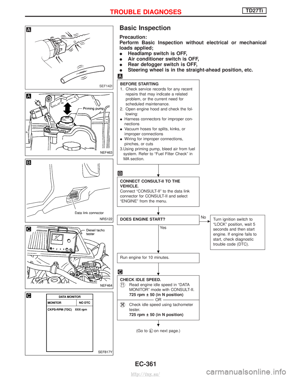
Basic Inspection
Precaution:
Perform Basic Inspection without electrical or mechanical
loads applied;
IHeadlamp switch is OFF,
I Air conditioner switch is OFF,
I Rear defogger switch is OFF,
I Steering wheel is in the straight-ahead position, etc.
BEFORE STARTING
1. Check service records for any recent
repairs that may indicate a related
problem, or the current need for
scheduled maintenance.
2. Open engine hood and check the fol- lowing:
I Harness connectors for improper con-
nections
I Vacuum hoses for splits, kinks, or
improper connections
I Wiring for improper connections,
pinches, or cuts
3.Using priming pump, bleed air from fuel system. Refer to ªFuel Filter Checkº in
MA section.
CONNECT CONSULT-II TO THE
VEHICLE.
Connect ªCONSULT-IIº to the data link
connector for CONSULT-II and select
ªENGINEº from the menu.
DOES ENGINE START?
Ye s
ENo Turn ignition switch to
ªLOCKº position, wait 5
seconds and then start
engine. If engine fails to
start, check diagnostic
trouble code (DTC).
Run engine for 10 minutes.
CHECK IDLE SPEED.
Read engine idle speed in ªDATA
MONITORº mode with CONSULT-II.
725 rpm 50 (in N position)
----------------------------------------------------------------------------------------------------------------------------------- -OR------------------------------------------------------------------------------------------------------------------------------------
Check idle speed using tachometer
tester.
725 rpm 50 (in N position)
(Go to qAon next page.)
SEF142I
NEF463
NRS122
NEF464
SEF817Y
H
H
H
H
H
TROUBLE DIAGNOSESTD27Ti
EC-361
http://vnx.su/
Page 814 of 1833
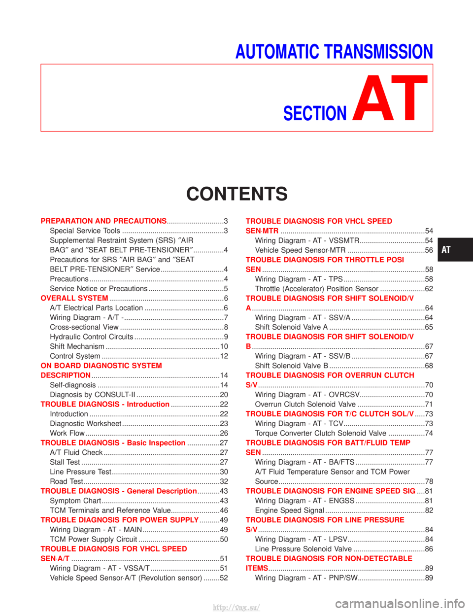
AUTOMATIC TRANSMISSIONSECTION
AT
CONTENTS
PREPARATION AND PRECAUTIONS ............................3
Special Service Tools ..................................................3
Supplemental Restraint System (SRS) ²AIR
BAG² and²SEAT BELT PRE-TENSIONER² ...............4
Precautions for SRS ²AIR BAG² and²SEAT
BELT PRE-TENSIONER² Service ...............................4
Precautions ..................................................................4
Service Notice or Precautions .....................................5
OVERALL SYSTEM ........................................................6
A/T Electrical Parts Location .......................................6
Wiring Diagram - A/T -.................................................7
Cross-sectional View ...................................................8
Hydraulic Control Circuits ............................................9
Shift Mechanism ........................................................10
Control System ..........................................................12
ON BOARD DIAGNOSTIC SYSTEM
DESCRIPTION ...............................................................14
Self-diagnosis ............................................................14
Diagnosis by CONSULT-II .........................................20
TROUBLE DIAGNOSIS - Introduction ........................22
Introduction ................................................................22
Diagnostic Worksheet ................................................23
Work Flow ..................................................................26
TROUBLE DIAGNOSIS - Basic Inspection ................27
A/T Fluid Check .........................................................27
Stall Test ....................................................................27
Line Pressure Test .....................................................30
Road Test...................................................................32
TROUBLE DIAGNOSIS - General Description ...........43
Symptom Chart ..........................................................43
TCM Terminals and Reference Value........................46
TROUBLE DIAGNOSIS FOR POWER SUPPLY ..........49
Wiring Diagram - AT - MAIN ......................................49
TCM Power Supply Circuit ........................................50
TROUBLE DIAGNOSIS FOR VHCL SPEED
SEN×A/T ........................................................................\
.51
Wiring Diagram - AT - VSSA/T ..................................51
Vehicle Speed Sensor×A/T (Revolution sensor) ........52 TROUBLE DIAGNOSIS FOR VHCL SPEED
SEN×MTR
.......................................................................54
Wiring Diagram - AT - VSSMTR ................................54
Vehicle Speed Sensor×MTR ......................................56
TROUBLE DIAGNOSIS FOR THROTTLE POSI
SEN ........................................................................\
........58
Wiring Diagram - AT - TPS ........................................58
Throttle (Accelerator) Position Sensor ......................62
TROUBLE DIAGNOSIS FOR SHIFT SOLENOID/V
A ........................................................................\
.............64
Wiring Diagram - AT - SSV/A ....................................64
Shift Solenoid Valve A ...............................................65
TROUBLE DIAGNOSIS FOR SHIFT SOLENOID/V
B ........................................................................\
.............67
Wiring Diagram - AT - SSV/B ....................................67
Shift Solenoid Valve B ...............................................68
TROUBLE DIAGNOSIS FOR OVERRUN CLUTCH
S/V ........................................................................\
..........70
Wiring Diagram - AT - OVRCSV................................70
Overrun Clutch Solenoid Valve .................................71
TROUBLE DIAGNOSIS FOR T/C CLUTCH SOL/V .....73
Wiring Diagram - AT - TCV........................................73
Torque Converter Clutch Solenoid Valve ..................74
TROUBLE DIAGNOSIS FOR BATT/FLUID TEMP
SEN ........................................................................\
........77
Wiring Diagram - AT - BA/FTS ..................................77
A/T Fluid Temperature Sensor and TCM Power
Source........................................................................\
78
TROUBLE DIAGNOSIS FOR ENGINE SPEED SIG ....81
Wiring Diagram - AT - ENGSS ..................................81
Engine Speed Signal .................................................82
TROUBLE DIAGNOSIS FOR LINE PRESSURE
S/V ........................................................................\
..........84
Wiring Diagram - AT - LPSV......................................84
Line Pressure Solenoid Valve ...................................86
TROUBLE DIAGNOSIS FOR NON-DETECTABLE
ITEMS........................................................................\
.....89 Wiring Diagram - AT - PNP/SW.................................89
http://vnx.su/
Page 817 of 1833
Supplemental Restraint System (SRS) ªAIR
BAGº and ªSEAT BELT PRE-TENSIONERº
The Supplemental Restraint System such as ªAIR BAGº and ªSEAT BELT PRE-TENSIONERº used along with
a seat belt, helps to reduce the risk or severity of injury to the driver and front passenger for certain types of
collision. The SRS composition which is available to NISSAN MODEL R20 is as follows (The composition
varies according to the destination and optional equipment.):
IFor a frontal collision
The Supplemental Restraint System consists of driver air bag module (located in the center of the steer-
ing wheel), front passenger air bag module (located on the instrument panel on passenger side), front seat
belt pre-tensioners, a diagnosis sensor unit, warning lamp, wiring harness and spiral cable.
I For a side collision
The Supplemental Restraint System consists of front side air bag module (located in the outer side of front
seat), side air bag (satellite) sensor, diagnosis sensor unit (one of components of air bags for a frontal
collision), wiring harness, warning lamp (one of components of air bags for a frontal collision).
WARNING:
I To avoid rendering the SRS inoperative, which could increase the risk of personal injury or death
in the event of a collision which would result in air bag inflation, all maintenance should be per-
formed by an authorized NISSAN dealer.
I Improper maintenance, including incorrect removal and installation of the SRS, can lead to per-
sonal injury caused by unintentional activation of the system.
I Do not use electrical test equipment on any circuit related to the SRS unless instructed to in this
Service Manual. Spiral cable and wiring harnesses covered with yellow insulation tape either just
before the harness connectors or for the complete harness are related to the SRS.
Precautions for SRS ªAIR BAGº and ªSEAT
BELT PRE-TENSIONERº Service
IDo not use electrical test equipment to check SRS circuits unless instructed to in this Service Manual.
I Before servicing the SRS, turn ignition switch ªOFFº, disconnect both battery cables and wait at least 3
minutes.
For approximately 3 minutes after the cables are removed, it is still possible for the air bag and seat belt
pre-tensioner to deploy. Therefore, do not work on any SRS connectors or wires until at least 3 minutes
have passed.
I Diagnosis sensor unit must always be installed with their arrow marks ª +º pointing towards the front of
the vehicle for proper operation. Also check diagnosis sensor unit for cracks, deformities or rust before
installation and replace as required.
I The spiral cable must be aligned with the neutral position since its rotations are limited. Do not attempt to
turn steering wheel or column after removal of steering gear.
I Handle air bag module carefully. Always place driver and front passenger air bag modules with the pad
side facing upward and place front side air bag module (built-in type) standing with stud bolt side setting
bottom.
I Conduct self-diagnosis to check entire SRS for proper function after replacing any components.
I After air bag inflates, the front instrument panel assembly should be replaced if damaged.
Precautions
IBefore proceeding with disassembly, thoroughly clean the outside of the transmission. It is important to
prevent the internal parts from becoming contaminated by dirt or other foreign matter.
I Disassembly should be done in a clean work area.
I Use lint-free cloth or towels for wiping parts clean. Common shop rags can leave fibers that could inter-
fere with the operation of the transmission.
I Place disassembled parts in order for easier and proper assembly.
I All parts should be carefully cleaned with a general purpose, non-flammable solvent before inspection or
reassembly.
I Gaskets, seals and O-rings should be replaced any time the transmission is disassembled.
I It is very important to perform functional tests whenever they are indicated.
I The valve body contains precision parts and requires extreme care when parts are removed and serviced.
Place removed parts in a parts rack in order to replace them in correct positions and sequences. Care will
also prevent springs and small parts from becoming scattered or lost.
I Properly installed valves, sleeves, plugs, etc. will slide along bores in valve body under their own weight.
PREPARATION AND PRECAUTIONS
AT- 4
http://vnx.su/
Page 818 of 1833
IBefore assembly, apply a coat of recommended ATF to all parts. Apply petroleum jelly to protect O-rings
and seals, and to hold bearings and washers in place during assembly. Do not use grease.
I Extreme care should be taken to avoid damage to O-rings, seals and gaskets when assembling.
I After overhaul, refill the transmission with new ATF.
I When the A/T drain plug is removed, only some of the fluid is drained. Old A/T fluid will remain in torque
converter and ATF cooling system.
Always follow the procedures under ªChanging A/T Fluidº in the MA section when changing A/T fluid.
Service Notice or Precautions
FAIL-SAFE
The TCM has an electronic Fail-Safe (limp home mode). This allows the vehicle to be driven even if a major
electrical input/output device circuit is damaged.
Under Fail-Safe, the vehicle always runs in third gear even with a shift lever position of ª1º, ª2º or ªDº. Cus-
tomer may complain of ªsluggish or poor accelerationº.
When the Fail-Safe operation occurs the next time the key is turned to the ªONº position, the SPORT indica-
tor lamp will blink for about 8 seconds. (For diagnosis, refer to AT-33.)
Fail-Safe may activate without electrical circuit damages if the vehicle is driven under extreme conditions (such
as excessive wheel spins and emergency braking immediately afterwards). In this case, turn the ignition key
ªOFFº for 5 seconds and then ªONº to recover normal shift pattern.
The blinking of the SPORT indicator lamp for about 8 seconds will appear only once and be cleared. The cus-
tomer may resume normal driving conditions by chance.
Always follow the ªWORK FLOWº (Refer to AT-26).
The SELF-DIAGNOSIS results will be as follows:
The first SELF-DIAGNOSIS will indicate the damage of the vehicle speed sensor or the revolution sensor.
During the next SELF-DIAGNOSIS performed after checking the sensor, no damages will be indicated.
PREPARATION AND PRECAUTIONS
Precautions (Cont'd)
AT- 5
http://vnx.su/